Electronic Troubleshooting. Chapter 10 Digital Circuits
|
|
|
- Augusta Caldwell
- 9 years ago
- Views:
Transcription
1 Electronic Troubleshooting Chapter 10 Digital Circuits

2 Digital Circuits Key Aspects Logic Gates Inverters NAND Gates Specialized Test Equipment MOS Circuits Flip-Flops and Counters

3 Logic Gates Characteristics A combinational Logic circuit with two or more inputs and one output OR Gates And Gates Exclusive OR Gates etc. Inputs are limited too two values High Logic 1 Often assumed to be +5V Low Logic 0 Often assumed to be 0V

4 Logic Gates Characteristics Inputs are limited too two values Possible combinations 2-inputs with 2-possible values => 4 permutations Permutations 2 n, n= number of inputs OR Gate

5 AND Gate Logic Gates
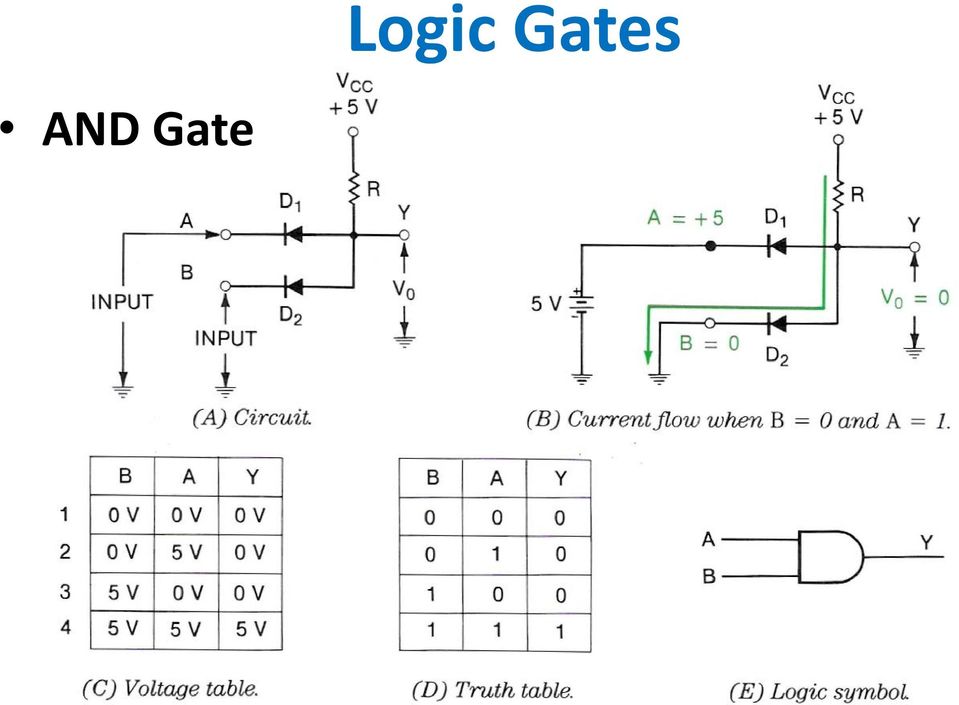
 results if one, and only one, of the inputs to the gate is HIGH (1). If both inputs are LOW (0) or both are HIGH (1), a LOW output (0) results.")
6 Logic Gates Exclusive OR Gate The XOR gate (sometimes EOR gate) is a digital logic gate that implements exclusive disjunction - it behaves according to the truth table A HIGH output (1) results if one, and only one, of the inputs to the gate is HIGH (1). If both inputs are LOW (0) or both are HIGH (1), a LOW output (0) results. Boolean algebra
 or both are HIGH (1), a LOW output (0) results.")
7 Logic Gates Sample Gate Application AND Gate What would the Output be with: OR Gate, XOR Gate


8 Inverters Characteristics Changes one logic level to the other Often needed in digital circuits Chapter 9 page 248» The R input to the flip-flop has an invert on it

9 Sample Application Inverters Notice the line over BURST. It is called BURST NOT

10 NAND Gates Key Aspects Can be built with the gates already covered An AND Gate followed by an Inverter So commonly used construction are available monolithic implementations Characteristics

11 Actual Gate Considerations Key Aspects Will use NAND Gates as a sub fro all gates Simplified /Improved Component Count Two emitters almost as easy in manufacturing as one Accomplished when artwork for the IC is made Three components less

12 Actual Gate Considerations Rise Time Problems Caused by the input capacitance of gates driven high TTL gates typically have a Fan out of 10 Thus the parallel connection the gate s input capacitance is significant Rise time we decrease if R2 was made smaller However significant current would flow when Q2 was turned on

13 Actual Gate Considerations Rise Time Problems Solution Use Totem Pole Output Totem Pole Operation When at least on input is low Q2 is off, No current in R3 and Q4 is off Q3 is on and R4 can be small and minimize the time constant for the output to go high» Whit a Low out Q3 is off When both inputs are High Reverse currents supply base of Q4

14 Actual Gate Considerations Rise Time Problems Totem Pole Operation When both inputs are High Reverse currents supply base of Q2, Q2 conducts Base of Q4 goes high and Q4 conducts Output is Low Much faster Rise times Since Q3 only conducts when the output is high, R3 can be sized to minimize the time constant and not cause a heat and efficiency problem

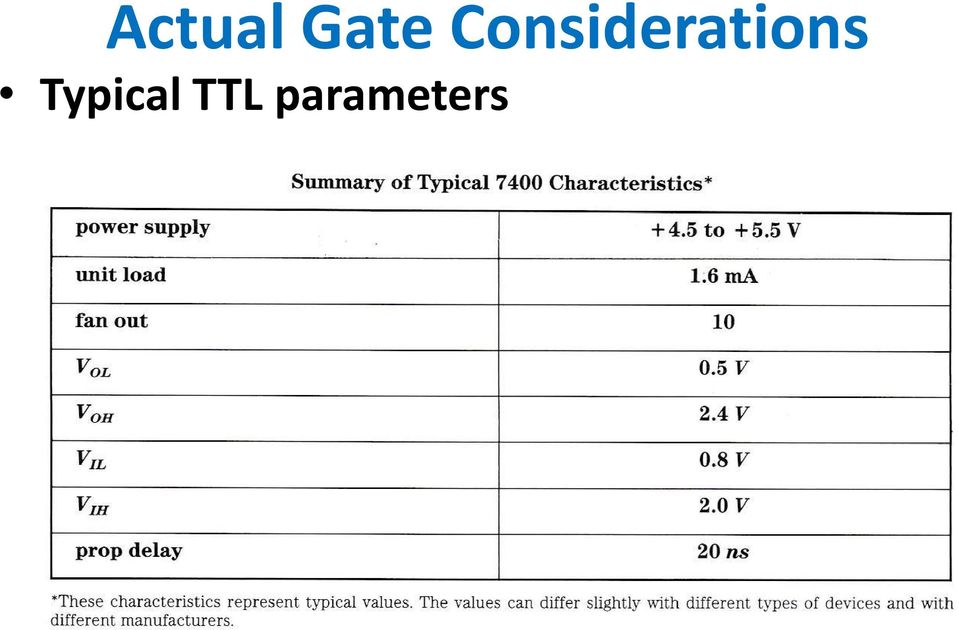
15 Actual Gate Considerations Typical TTL parameters
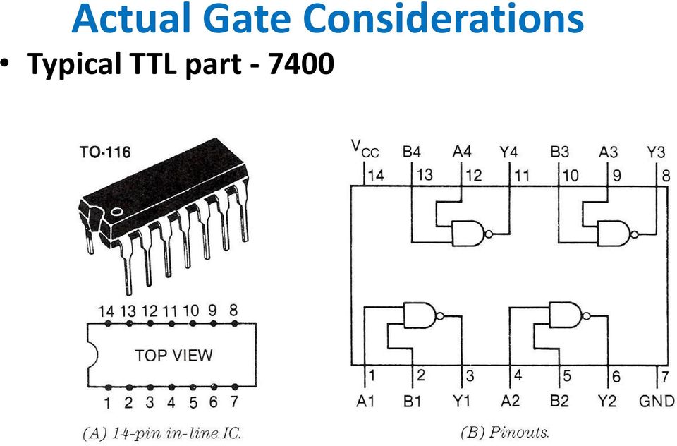
16 Actual Gate Considerations Typical TTL part
17 Actual Gate Considerations Standard 74 series TTL has evolved into other series: Standard TTL, 74 series Schottky TTL, 74S series Low power Schottky TTL, 74LS series (LS-TTL) Advanced Schottky TTL, 74AS series (AS-TTL) Advanced low power Schottky TTL, 74ALS series 74F fast TTL
 Advanced low power Schottky TTL, 74ALS series 74F")
18 Specialized Test Equipment Logic Probe Example: Instek GLP-1A Logic Probe

19 Specialized Test Equipment Digital Pulser Digital Pulser (SJ-1) Accurate Timebase Generator Output: Open Collector (Interfaceable with any Logic Circuits) Supply: 4.5V-18VDC 9 Selectable Output Frequencies: 16MHz (crystal osc. output), 8MHz, 1MHz, 100KHz, 10KHz, 1KHz, 100Hz, 10Hz & 1Hz.

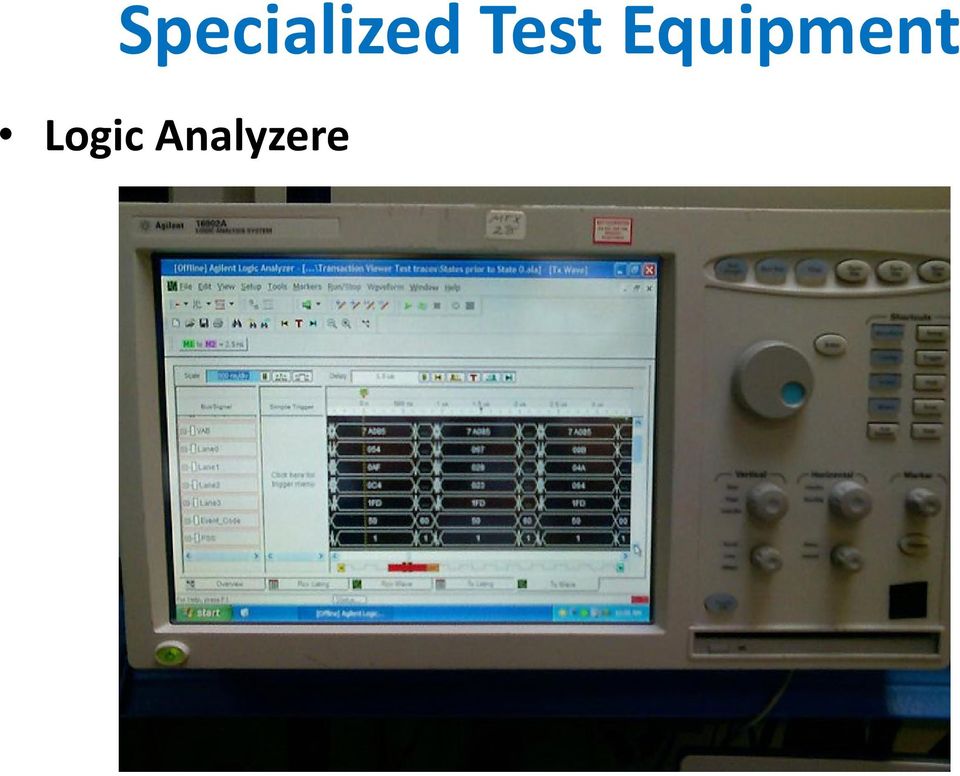
20 Specialized Test Equipment Logic Analyzere
21 Specialized Test Equipment Testing a gate in a Live Circuit
22 MOS Circuits Characteristics Most common type is CMOS Complementary MOS Circuits use both P-Channel and N-Channel devices in the same circuit CMOS Circuits consume very little power Most of the TTL logic gates have been implemented in CMOS Typical Gates covered Inverters and NOR gates Inverter Same logic symbol as for the TTL version Same truth table
23 MOS Circuits Inverter Circuit Operation With the input at ground Logic 0 0V Gate-source on the N-Channel device (Q2) and it is off -Vdd Gate to-source on Q1 and it is on and acts like a 1000 Ω resistor Vdd on the output With the input at ground Logic 1 Q1 conducts and appears as a 1000 Ω resistor Q2 is off and appears as an open
24 MOS Circuits NOR Gate Characteristics Refer to Figure on page 281 of the textbook Logic table Logic 1 out only with all logic 0s on the input Construction Two P channel MOSFETs connected to the inputs and connected in series with the VDD and the output Two N channel MOSFETs connected to the inputs and in parallel between the output and ground Circuit Operation With both inputs at ground A & B at Logic 0 Q1 and Q2 turn on and conduct Q3 and Q4 are open and not conducting - VDD appears at the Output
25 MOS Circuits NOR Gate Circuit Operation With both inputs, A & B at Logic 0 Q1 and Q2 turn on and conduct Q3 and Q4 are open and not conducting - VDD appears at the Output With either or both A & B at Logic 1 Either Q1 or Q2, or both are turned off and not conducting much Either Q3, Q4, or both are turned on and conducting Logic 0 appears at the Output CMOS Characteristics See chart on the next slide Handling Precautions see top of page 283
26 MOS Circuits CMOS Characteristics
27 Flip-Flops and Counters Characteristics Used to make sequential logic circuits Outputs depend upon: A previous event Combinational logic inputs The circuits remember what has happened Covered topics RS Flip-Flops D Flip-Flops J-K Flip-Flops Binary and Decade Counters 7-Segment displays
28 Flip-Flops and Counters RS Flip-Flops Can be implemented using NAND, NOR, AND, OR, and Inverters NOR gate Implementation Lower right drawing Used ½ of a 7402 IC Inputs are Active Highs A high input will change the state of the Gate NAND gate Implementation Used ½ of a 7400 IC
29 Flip-Flops and Counters RS Flip-Flops NAND gate Implementation Notice on the circuit and the logic symbol Active Low inputs A Low input will change the state of the Gate A High input will not effect the output Other implementations use AND & OR gates with inverters See NAND Gates below
30 Flip-Flops and Counters RS Flip-Flops NAND Gate version Alternate Logic symbol drawing Also Pull-Up Resistor
31 Flip-Flops and Counters D Flip-Flops Operation Logic symbol arrows indicate I/O PR and CLR act like the Set (S) and Reset (R) inputs on a NAND Gate R-S Filip-Flop Q and Q are always in opposite states The input CK (clock) on a positive transition causes Q to go either high or low depending on the D input Q s state will match the state of D at that time
32 Flip-Flops and Counters J-K Flip-Flops Operation Has same PR and CLR as type D Has two inputs J and K instead of the D input See the truth Table Has an additional MODE of operation Toggle» Outputs will toggle when a new clock pulse arrives at the CK pin Bubble on the CK indicates that negative transition is active
33 Flip-Flops and Counters Binary Counter using J-K Flip-Flops Q output acts as the clock input to the next Flip-Flop Walk through the circuit and timing diagram
34 Flip-Flops and Counters Sample Monolithic Counter 7493 Can be a 3-bit or 4-bit counter Wire QA output to input B for 4-bit» MOD 16 counter Otherwise use input B» MOD 8 counter 14 pin DIP
35 Flip-Flops and Counters Sample Monolithic Counter 7490 Decade counter Counts 0 9 and can be reset to zero Has 4 outputs Reference
36 Flip-Flops and Counters BCD Displays A common Anode version is shown Common Cathode versions are also available
37 Flip-Flops and Counters Interface Circuit The BCD counters output binary that resets after 9 The 7 segment display with decimal point has eight inputs that cause numbers 0-9 to display The 7447 is a seven segment display driver that translates binary counts into a seven segment inputs See pages 291 and 292
Counters and Decoders
 Physics 3330 Experiment #10 Fall 1999 Purpose Counters and Decoders In this experiment, you will design and construct a 4-bit ripple-through decade counter with a decimal read-out display. Such a counter
The components. E3: Digital electronics. Goals:
 E3: Digital electronics Goals: Basic understanding of logic circuits. Become familiar with the most common digital components and their use. Equipment: 1 st. LED bridge 1 st. 7-segment display. 2 st. IC
Having read this workbook you should be able to: recognise the arrangement of NAND gates used to form an S-R flip-flop.
 Objectives Having read this workbook you should be able to: recognise the arrangement of NAND gates used to form an S-R flip-flop. describe how such a flip-flop can be SET and RESET. describe the disadvantage
Module 3: Floyd, Digital Fundamental
 Module 3: Lecturer : Yongsheng Gao Room : Tech - 3.25 Email : [email protected] Structure : 6 lectures 1 Tutorial Assessment: 1 Laboratory (5%) 1 Test (20%) Textbook : Floyd, Digital Fundamental
Experiment # 9. Clock generator circuits & Counters. Eng. Waleed Y. Mousa
 Experiment # 9 Clock generator circuits & Counters Eng. Waleed Y. Mousa 1. Objectives: 1. Understanding the principles and construction of Clock generator. 2. To be familiar with clock pulse generation
Upon completion of unit 1.1, students will be able to
 Upon completion of unit 1.1, students will be able to 1. Demonstrate safety of the individual, class, and overall environment of the classroom/laboratory, and understand that electricity, even at the nominal
Decimal Number (base 10) Binary Number (base 2)
 Binary Number (base 2)") LECTURE 5. BINARY COUNTER Before starting with counters there is some vital information that needs to be understood. The most important is the fact that since the outputs of a digital chip can only be
LECTURE 5. BINARY COUNTER Before starting with counters there is some vital information that needs to be understood. The most important is the fact that since the outputs of a digital chip can only be
COMBINATIONAL and SEQUENTIAL LOGIC CIRCUITS Hardware implementation and software design
 PH-315 COMINATIONAL and SEUENTIAL LOGIC CIRCUITS Hardware implementation and software design A La Rosa I PURPOSE: To familiarize with combinational and sequential logic circuits Combinational circuits
DEPARTMENT OF INFORMATION TECHNLOGY
 DRONACHARYA GROUP OF INSTITUTIONS, GREATER NOIDA Affiliated to Mahamaya Technical University, Noida Approved by AICTE DEPARTMENT OF INFORMATION TECHNLOGY Lab Manual for Computer Organization Lab ECS-453
CHAPTER 11: Flip Flops
 CHAPTER 11: Flip Flops In this chapter, you will be building the part of the circuit that controls the command sequencing. The required circuit must operate the counter and the memory chip. When the teach
MULTIPLE CHOICE. Choose the one alternative that best completes the statement or answers the question.
 CHAPTER3 QUESTIONS MULTIPLE CHOICE. Choose the one alternative that best completes the statement or answers the question. ) If one input of an AND gate is LOW while the other is a clock signal, the output
ETEC 2301 Programmable Logic Devices. Chapter 10 Counters. Shawnee State University Department of Industrial and Engineering Technologies
 ETEC 2301 Programmable Logic Devices Chapter 10 Counters Shawnee State University Department of Industrial and Engineering Technologies Copyright 2007 by Janna B. Gallaher Asynchronous Counter Operation
Sequential Logic Design Principles.Latches and Flip-Flops
 Sequential Logic Design Principles.Latches and Flip-Flops Doru Todinca Department of Computers Politehnica University of Timisoara Outline Introduction Bistable Elements Latches and Flip-Flops S-R Latch
Lecture 8: Synchronous Digital Systems
 Lecture 8: Synchronous Digital Systems The distinguishing feature of a synchronous digital system is that the circuit only changes in response to a system clock. For example, consider the edge triggered
Operating Manual Ver.1.1
 4 Bit Binary Ripple Counter (Up-Down Counter) Operating Manual Ver.1.1 An ISO 9001 : 2000 company 94-101, Electronic Complex Pardesipura, Indore- 452010, India Tel : 91-731- 2570301/02, 4211100 Fax: 91-731-
Chapter 8. Sequential Circuits for Registers and Counters
 Chapter 8 Sequential Circuits for Registers and Counters Lesson 3 COUNTERS Ch16L3- "Digital Principles and Design", Raj Kamal, Pearson Education, 2006 2 Outline Counters T-FF Basic Counting element State
ENGI 241 Experiment 5 Basic Logic Gates
 ENGI 24 Experiment 5 Basic Logic Gates OBJECTIVE This experiment will examine the operation of the AND, NAND, OR, and NOR logic gates and compare the expected outputs to the truth tables for these devices.
Contents COUNTER. Unit III- Counters
 COUNTER Contents COUNTER...1 Frequency Division...2 Divide-by-2 Counter... 3 Toggle Flip-Flop...3 Frequency Division using Toggle Flip-flops...5 Truth Table for a 3-bit Asynchronous Up Counter...6 Modulo
Gates, Circuits, and Boolean Algebra
 Gates, Circuits, and Boolean Algebra Computers and Electricity A gate is a device that performs a basic operation on electrical signals Gates are combined into circuits to perform more complicated tasks
DIGITAL COUNTERS. Q B Q A = 00 initially. Q B Q A = 01 after the first clock pulse.
 DIGITAL COUNTERS http://www.tutorialspoint.com/computer_logical_organization/digital_counters.htm Copyright tutorialspoint.com Counter is a sequential circuit. A digital circuit which is used for a counting
Asynchronous Counters. Asynchronous Counters
 Counters and State Machine Design November 25 Asynchronous Counters ENGI 25 ELEC 24 Asynchronous Counters The term Asynchronous refers to events that do not occur at the same time With respect to counter
EXPERIMENT 8. Flip-Flops and Sequential Circuits
 EXPERIMENT 8. Flip-Flops and Sequential Circuits I. Introduction I.a. Objectives The objective of this experiment is to become familiar with the basic operational principles of flip-flops and counters.
A Lesson on Digital Clocks, One Shots and Counters
 A Lesson on Digital Clocks, One Shots and Counters Topics Clocks & Oscillators LM 555 Timer IC Crystal Oscillators Selection of Variable Resistors Schmitt Gates Power-On Reset Circuits One Shots Counters
Digital Electronics Detailed Outline
 Digital Electronics Detailed Outline Unit 1: Fundamentals of Analog and Digital Electronics (32 Total Days) Lesson 1.1: Foundations and the Board Game Counter (9 days) 1. Safety is an important concept
DIGITAL ELECTRONICS. Counters. By: Electrical Engineering Department
 Counters By: Electrical Engineering Department 1 Counters Upon completion of the chapter, students should be able to:.1 Understand the basic concepts of asynchronous counter and synchronous counters, and
Chapter 10 Advanced CMOS Circuits
 Transmission Gates Chapter 10 Advanced CMOS Circuits NMOS Transmission Gate The active pull-up inverter circuit leads one to thinking about alternate uses of NMOS devices. Consider the circuit shown in
A Digital Timer Implementation using 7 Segment Displays
 A Digital Timer Implementation using 7 Segment Displays Group Members: Tiffany Sham u2548168 Michael Couchman u4111670 Simon Oseineks u2566139 Caitlyn Young u4233209 Subject: ENGN3227 - Analogue Electronics
Take-Home Exercise. z y x. Erik Jonsson School of Engineering and Computer Science. The University of Texas at Dallas
 Take-Home Exercise Assume you want the counter below to count mod-6 backward. That is, it would count 0-5-4-3-2-1-0, etc. Assume it is reset on startup, and design the wiring to make the counter count
Digital Logic Elements, Clock, and Memory Elements
 Physics 333 Experiment #9 Fall 999 Digital Logic Elements, Clock, and Memory Elements Purpose This experiment introduces the fundamental circuit elements of digital electronics. These include a basic set
CHAPTER 11 LATCHES AND FLIP-FLOPS
 CHAPTER 11 LATCHES AND FLIP-FLOPS This chapter in the book includes: Objectives Study Guide 11.1 Introduction 11.2 Set-Reset Latch 11.3 Gated D Latch 11.4 Edge-Triggered D Flip-Flop 11.5 S-R Flip-Flop
A Lesson on Digital Clocks, One Shots and Counters
 A Lesson on Digital Clocks, One Shots and Counters Topics Clocks & Oscillators LM 555 Timer IC Crystal Oscillators Selection of Variable Resistors Schmitt Gates Power-On Reset Circuits One Shots Counters
INTEGRATED CIRCUITS. For a complete data sheet, please also download:
 INTEGRATED CIRCUITS DATA SHEET For a complete data sheet, please also download: The IC06 74HC/HCT/HCU/HCMOS Logic Family Specifications The IC06 74HC/HCT/HCU/HCMOS Logic Package Information The IC06 74HC/HCT/HCU/HCMOS
BINARY CODED DECIMAL: B.C.D.
 BINARY CODED DECIMAL: B.C.D. ANOTHER METHOD TO REPRESENT DECIMAL NUMBERS USEFUL BECAUSE MANY DIGITAL DEVICES PROCESS + DISPLAY NUMBERS IN TENS IN BCD EACH NUMBER IS DEFINED BY A BINARY CODE OF 4 BITS.
Digital circuits make up all computers and computer systems. The operation of digital circuits is based on
 Digital Logic Circuits Digital circuits make up all computers and computer systems. The operation of digital circuits is based on Boolean algebra, the mathematics of binary numbers. Boolean algebra is
1. True or False? A voltage level in the range 0 to 2 volts is interpreted as a binary 1.
 File: chap04, Chapter 04 1. True or False? A voltage level in the range 0 to 2 volts is interpreted as a binary 1. 2. True or False? A gate is a device that accepts a single input signal and produces one
Digital Systems Based on Principles and Applications of Electrical Engineering/Rizzoni (McGraw Hill
 Digital Systems Based on Principles and Applications of Electrical Engineering/Rizzoni (McGraw Hill Objectives: Analyze the operation of sequential logic circuits. Understand the operation of digital counters.
Digital Fundamentals. Lab 8 Asynchronous Counter Applications
 Richland College Engineering Technology Rev. 0 B. Donham Rev. 1 (7/2003). Horne Rev. 2 (1/2008). Bradbury Digital Fundamentals CETT 1425 Lab 8 Asynchronous Counter Applications Name: Date: Objectives:
Design: a mod-8 Counter
 Design: a mod-8 Counter A mod-8 counter stores a integer value, and increments that value (say) on each clock tick, and wraps around to 0 if the previous stored value was 7. So, the stored value follows
Sequential Logic. (Materials taken from: Principles of Computer Hardware by Alan Clements )
") Sequential Logic (Materials taken from: Principles of Computer Hardware by Alan Clements ) Sequential vs. Combinational Circuits Combinatorial circuits: their outputs are computed entirely from their present
Sequential Logic (Materials taken from: Principles of Computer Hardware by Alan Clements ) Sequential vs. Combinational Circuits Combinatorial circuits: their outputs are computed entirely from their present
PLL frequency synthesizer
 ANALOG & TELECOMMUNICATION ELECTRONICS LABORATORY EXERCISE 4 Lab 4: PLL frequency synthesizer 1.1 Goal The goals of this lab exercise are: - Verify the behavior of a and of a complete PLL - Find capture
Seven-Segment LED Displays
 Seven-Segment LED Displays Nicholas Neumann 11/19/2010 Abstract Seven-segment displays are electronic display devices used as an easy way to display decimal numerals and an alterative to the more complex
[ 4 ] Logic Symbols and Truth Table
![[ 4 ] Logic Symbols and Truth Table](/thumbs/40/21640854.jpg "[ 4 ] Logic Symbols and Truth Table") [ 4 ] Logic s and Truth Table 1. How to Read MIL-Type Logic s Table 1.1 shows the MIL-type logic symbols used for high-speed CMO ICs. This logic chart is based on MIL-TD-806. The clocked inverter and transmission
[ 4 ] Logic s and Truth Table 1. How to Read MIL-Type Logic s Table 1.1 shows the MIL-type logic symbols used for high-speed CMO ICs. This logic chart is based on MIL-TD-806. The clocked inverter and transmission
WEEK 8.1 Registers and Counters. ECE124 Digital Circuits and Systems Page 1
 WEEK 8.1 egisters and Counters ECE124 igital Circuits and Systems Page 1 Additional schematic FF symbols Active low set and reset signals. S Active high set and reset signals. S ECE124 igital Circuits
Design Example: Counters. Design Example: Counters. 3-Bit Binary Counter. 3-Bit Binary Counter. Other useful counters:
 Design Eample: ers er: a sequential circuit that repeats a specified sequence of output upon clock pulses. A,B,C,, Z. G, O, T, E, R, P, S,!.,,,,,,,7. 7,,,,,,,.,,,,,,,,,,,. Binary counter: follows the binary
3.Basic Gate Combinations
 3.Basic Gate Combinations 3.1 TTL NAND Gate In logic circuits transistors play the role of switches. For those in the TTL gate the conducting state (on) occurs when the baseemmiter signal is high, and
Copyright Peter R. Rony 2009. All rights reserved.
 Experiment No. 1. THE DIGI DESIGNER Experiment 1-1. Socket Connections on the Digi Designer Experiment No. 2. LOGIC LEVELS AND THE 7400 QUADRUPLE 2-INPUT POSITIVE NAND GATE Experiment 2-1. Truth Table
Gates & Boolean Algebra. Boolean Operators. Combinational Logic. Introduction
 Introduction Gates & Boolean lgebra Boolean algebra: named after mathematician George Boole (85 864). 2-valued algebra. digital circuit can have one of 2 values. Signal between and volt =, between 4 and
Here we introduced (1) basic circuit for logic and (2)recent nano-devices, and presented (3) some practical issues on nano-devices.
 basic circuit for logic and (2)recent nano-devices, and presented (3) some practical issues on nano-devices.") Outline Here we introduced () basic circuit for logic and (2)recent nano-devices, and presented (3) some practical issues on nano-devices. Circuit Logic Gate A logic gate is an elemantary building block
Outline Here we introduced () basic circuit for logic and (2)recent nano-devices, and presented (3) some practical issues on nano-devices. Circuit Logic Gate A logic gate is an elemantary building block
CD4027BC Dual J-K Master/Slave Flip-Flop with Set and Reset
 October 1987 Revised March 2002 CD4027BC Dual J-K Master/Slave Flip-Flop with Set and Reset General Description The CD4027BC dual J-K flip-flops are monolithic complementary MOS (CMOS) integrated circuits
CD4013BC Dual D-Type Flip-Flop
 CD4013BC Dual D-Type Flip-Flop General Description The CD4013B dual D-type flip-flop is a monolithic complementary MOS (CMOS) integrated circuit constructed with N- and P-channel enhancement mode transistors.
NOTE: The Flatpak version has the same pinouts (Connection Diagram) as the Dual In-Line Package.
 as the Dual In-Line Package.") PRESETTABLE BCD/DECADE UP/DOWN COUNTERS PRESETTABLE 4-BIT BINARY UP/DOWN COUNTERS The SN54/74LS90 is a synchronous UP/DOWN BCD Decade (842) Counter and the SN54/74LS9 is a synchronous UP/DOWN Modulo-6
PRESETTABLE BCD/DECADE UP/DOWN COUNTERS PRESETTABLE 4-BIT BINARY UP/DOWN COUNTERS The SN54/74LS90 is a synchronous UP/DOWN BCD Decade (842) Counter and the SN54/74LS9 is a synchronous UP/DOWN Modulo-6
Digital Logic Design Sequential circuits
 Digital Logic Design Sequential circuits Dr. Eng. Ahmed H. Madian E-mail: [email protected] Dr. Eng. Rania.Swief E-mail: [email protected] Dr. Eng. Ahmed H. Madian Registers An n-bit register
ELEC 2210 - EXPERIMENT 1 Basic Digital Logic Circuits
 Objectives ELEC - EXPERIMENT Basic Digital Logic Circuits The experiments in this laboratory exercise will provide an introduction to digital electronic circuits. You will learn how to use the IDL-00 Bit
Physics 120 Lab 6: Field Effect Transistors - Ohmic region
 Physics 120 Lab 6: Field Effect Transistors - Ohmic region The FET can be used in two extreme ways. One is as a voltage controlled resistance, in the so called "Ohmic" region, for which V DS < V GS - V
3-Digit Counter and Display
 ECE 2B Winter 2007 Lab #7 7 3-Digit Counter and Display This final lab brings together much of what we have done in our lab experiments this quarter to construct a simple tachometer circuit for measuring
Chapter 6 TRANSISTOR-TRANSISTOR LOGIC. 3-emitter transistor.
 Chapter 6 TRANSISTOR-TRANSISTOR LOGIC The evolution from DTL to TTL can be seen by observing the placement of p-n junctions. For example, the diode D2 from Figure 2 in the chapter on DTL can be replaced
ECE124 Digital Circuits and Systems Page 1
 ECE124 Digital Circuits and Systems Page 1 Chip level timing Have discussed some issues related to timing analysis. Talked briefly about longest combinational path for a combinational circuit. Talked briefly
List of Experiment. 8. To study and verify the BCD to Seven Segments DECODER.(IC-7447).
.") G. H. RAISONI COLLEGE OF ENGINEERING, NAGPUR Department of Electronics & Communication Engineering Branch:-4 th Semester[Electronics] Subject: - Digital Circuits List of Experiment Sr. Name Of Experiment
G. H. RAISONI COLLEGE OF ENGINEERING, NAGPUR Department of Electronics & Communication Engineering Branch:-4 th Semester[Electronics] Subject: - Digital Circuits List of Experiment Sr. Name Of Experiment
Napier University. School of Engineering. Electronic Engineering A Module: SE42205 Digital Design
 Napier University School of Engineering Digital Design Clock + U1 out 5V "1" "2" "4" JK-FF D JK-FF C JK-FF B U8 SN7408 signal U4 SN74107 U5 SN74107 U6 SN74107 U3 SN7408 U2 J Q J Q & J Q & K CQ K CQ K CQ
Chapter 9 Latches, Flip-Flops, and Timers
 ETEC 23 Programmable Logic Devices Chapter 9 Latches, Flip-Flops, and Timers Shawnee State University Department of Industrial and Engineering Technologies Copyright 27 by Janna B. Gallaher Latches A temporary
CHAPTER 3 Boolean Algebra and Digital Logic
 CHAPTER 3 Boolean Algebra and Digital Logic 3.1 Introduction 121 3.2 Boolean Algebra 122 3.2.1 Boolean Expressions 123 3.2.2 Boolean Identities 124 3.2.3 Simplification of Boolean Expressions 126 3.2.4
LAB #4 Sequential Logic, Latches, Flip-Flops, Shift Registers, and Counters
 LAB #4 Sequential Logic, Latches, Flip-Flops, Shift Registers, and Counters LAB OBJECTIVES 1. Introduction to latches and the D type flip-flop 2. Use of actual flip-flops to help you understand sequential
To design digital counter circuits using JK-Flip-Flop. To implement counter using 74LS193 IC.
 8.1 Objectives To design digital counter circuits using JK-Flip-Flop. To implement counter using 74LS193 IC. 8.2 Introduction Circuits for counting events are frequently used in computers and other digital
Neonixie 6 Digit Nixie Clock Controller Introduction and Assembly
 Neonixie 6 Digit Nixie Clock Controller Introduction and Assembly Thank you for purchasing our 6 Digit Nixie Clock Controller. Our clock controller is user friendly and has many of the features most requested
So far we have investigated combinational logic for which the output of the logic devices/circuits depends only on the present state of the inputs.
 equential Logic o far we have investigated combinational logic for which the output of the logic devices/circuits depends only on the present state of the inputs. In sequential logic the output of the
FORDHAM UNIVERSITY CISC 3593. Dept. of Computer and Info. Science Spring, 2011. Lab 2. The Full-Adder
 FORDHAM UNIVERSITY CISC 3593 Fordham College Lincoln Center Computer Organization Dept. of Computer and Info. Science Spring, 2011 Lab 2 The Full-Adder 1 Introduction In this lab, the student will construct
CpE358/CS381. Switching Theory and Logical Design. Class 4
 Switching Theory and Logical Design Class 4 1-122 Today Fundamental concepts of digital systems (Mano Chapter 1) Binary codes, number systems, and arithmetic (Ch 1) Boolean algebra (Ch 2) Simplification
Latches, the D Flip-Flop & Counter Design. ECE 152A Winter 2012
 Latches, the D Flip-Flop & Counter Design ECE 52A Winter 22 Reading Assignment Brown and Vranesic 7 Flip-Flops, Registers, Counters and a Simple Processor 7. Basic Latch 7.2 Gated SR Latch 7.2. Gated SR
Lab 11 Digital Dice. Figure 11.0. Digital Dice Circuit on NI ELVIS II Workstation
 Lab 11 Digital Dice Figure 11.0. Digital Dice Circuit on NI ELVIS II Workstation From the beginning of time, dice have been used for games of chance. Cubic dice similar to modern dice date back to before
ARRL Morse Code Oscillator, How It Works By: Mark Spencer, WA8SME
 The national association for AMATEUR RADIO ARRL Morse Code Oscillator, How It Works By: Mark Spencer, WA8SME This supplement is intended for use with the ARRL Morse Code Oscillator kit, sold separately.
Digital Logic Design. Basics Combinational Circuits Sequential Circuits. Pu-Jen Cheng
 Digital Logic Design Basics Combinational Circuits Sequential Circuits Pu-Jen Cheng Adapted from the slides prepared by S. Dandamudi for the book, Fundamentals of Computer Organization and Design. Introduction
Memory Elements. Combinational logic cannot remember
 Memory Elements Combinational logic cannot remember Output logic values are function of inputs only Feedback is needed to be able to remember a logic value Memory elements are needed in most digital logic
CD4027BM CD4027BC Dual J-K Master Slave Flip-Flop with Set and Reset
 CD4027BM CD4027BC Dual J-K Master Slave Flip-Flop with Set and Reset General Description These dual J-K flip-flops are monolithic complementary MOS (CMOS) integrated circuits constructed with N- and P-
Interfacing To Alphanumeric Displays
 Interfacing To Alphanumeric Displays To give directions or data values to users, many microprocessor-controlled instruments and machines need to display letters of the alphabet and numbers. In systems
1.1 The 7493 consists of 4 flip-flops with J-K inputs unconnected. In a TTL chip, unconnected inputs
 CALIFORNIA STATE UNIVERSITY LOS ANGELES Department of Electrical and Computer Engineering EE-246 Digital Logic Lab EXPERIMENT 1 COUNTERS AND WAVEFORMS Text: Mano, Digital Design, 3rd & 4th Editions, Sec.
3-Phase DC Brushless Motor Pre-Drivers Technical Information NJM2625A
 3Phase DC Brushless Motor PreDrivers 1.FEATURE NJM2625 is a controller and predriver for speed control 3phase blushless DC motor. The device provides the proper sequencing of 3phase drive output with external
A simple RF/Microwave frequency counter
 Matjaz Vidmar, S53MV A simple RF/Microwave frequency counter I decided to design a simple, easily reproducible counter around a PIC 16F876A. The basic counter range is extended to at least 180MHz using
Analog & Digital Electronics Course No: PH-218
 Analog & Digital Electronics Course No: PH-218 Lec-28: Logic Gates & Family Course Instructor: Dr. A. P. VAJPEYI Department of Physics, Indian Institute of Technology Guwahati, India 1 Digital Logic Gates
NTE2053 Integrated Circuit 8 Bit MPU Compatible A/D Converter
 NTE2053 Integrated Circuit 8 Bit MPU Compatible A/D Converter Description: The NTE2053 is a CMOS 8 bit successive approximation Analog to Digital converter in a 20 Lead DIP type package which uses a differential
Application Note AN-940
 Application Note AN-940 How P-Channel MOSFETs Can Simplify Your Circuit Table of Contents Page 1. Basic Characteristics of P-Channel HEXFET Power MOSFETs...1 2. Grounded Loads...1 3. Totem Pole Switching
CS311 Lecture: Sequential Circuits
 CS311 Lecture: Sequential Circuits Last revised 8/15/2007 Objectives: 1. To introduce asynchronous and synchronous flip-flops (latches and pulsetriggered, plus asynchronous preset/clear) 2. To introduce
DM9368 7-Segment Decoder/Driver/Latch with Constant Current Source Outputs
 DM9368 7-Segment Decoder/Driver/Latch with Constant Current Source Outputs General Description The DM9368 is a 7-segment decoder driver incorporating input latches and constant current output circuits
Binary Adders: Half Adders and Full Adders
 Binary Adders: Half Adders and Full Adders In this set of slides, we present the two basic types of adders: 1. Half adders, and 2. Full adders. Each type of adder functions to add two binary bits. In order
Gray Code Generator and Decoder by Carsten Kristiansen Napier University. November 2004
 Gray Code Generator and Decoder by Carsten Kristiansen Napier University November 2004 Title page Author: Carsten Kristiansen. Napier No: 04007712. Assignment title: Design of a Gray Code Generator and
DS1307ZN. 64 x 8 Serial Real-Time Clock
 DS137 64 x 8 Serial Real-Time Clock www.maxim-ic.com FEATURES Real-time clock (RTC) counts seconds, minutes, hours, date of the month, month, day of the week, and year with leap-year compensation valid
SEQUENTIAL CIRCUITS. Block diagram. Flip Flop. S-R Flip Flop. Block Diagram. Circuit Diagram
 SEQUENTIAL CIRCUITS http://www.tutorialspoint.com/computer_logical_organization/sequential_circuits.htm Copyright tutorialspoint.com The combinational circuit does not use any memory. Hence the previous
Flip-Flops, Registers, Counters, and a Simple Processor
 June 8, 22 5:56 vra235_ch7 Sheet number Page number 349 black chapter 7 Flip-Flops, Registers, Counters, and a Simple Processor 7. Ng f3, h7 h6 349 June 8, 22 5:56 vra235_ch7 Sheet number 2 Page number
SN54/74LS192 SN54/74LS193
 PRESEABLE BCD/DECADE UP/DOWN COUNER PRESEABLE 4-BI BINARY UP/DOWN COUNER he SN4/74LS2 is an UP/DOWN BCD Decade (842) Counter and the SN4/74LS3 is an UP/DOWN MODULO-6 Binary Counter. Separate Count Up and
Obsolete Product(s) - Obsolete Product(s)
 - Obsolete Product(s)") SYNCHRONOUS PROGRAMMABLE 4-BIT BINARY COUNTER WITH ASYNCHRONOUS CLEAR INTERNAL LOOK-AHEAD FOR FAST COUNTING CARRY OUTPUT FOR CASCADING SYNCHRONOUSLY PROGRAMMABLE LOW-POWER TTL COMPATIBILITY STANDARDIZED
SYNCHRONOUS PROGRAMMABLE 4-BIT BINARY COUNTER WITH ASYNCHRONOUS CLEAR INTERNAL LOOK-AHEAD FOR FAST COUNTING CARRY OUTPUT FOR CASCADING SYNCHRONOUSLY PROGRAMMABLE LOW-POWER TTL COMPATIBILITY STANDARDIZED
ASYNCHRONOUS COUNTERS
 LB no.. SYNCHONOUS COUNTES. Introduction Counters are sequential logic circuits that counts the pulses applied at their clock input. They usually have 4 bits, delivering at the outputs the corresponding
Table 1 Comparison of DC, Uni-Polar and Bi-polar Stepper Motors
 Electronics Exercise 3: Uni-Polar Stepper Motor Controller / Driver Mechatronics Instructional Laboratory Woodruff School of Mechanical Engineering Georgia Institute of Technology Lab Director: I. Charles
2 : BISTABLES. In this Chapter, you will find out about bistables which are the fundamental building blocks of electronic counting circuits.
 2 : BITABLE In this Chapter, you will find out about bistables which are the fundamental building blos of electronic counting circuits. et-reset bistable A bistable circuit, also called a latch, or flip-flop,
DIGITAL TECHNICS II. Dr. Bálint Pődör. Óbuda University, Microelectronics and Technology Institute
 DIGITAL TECHNICS II Dr. Bálint Pődör Óbuda University, Microelectronics and Technology Institute 2. LECTURE: ELEMENTARY SEUENTIAL CIRCUITS: FLIP-FLOPS 1st year BSc course 2nd (Spring) term 2012/2013 1
DATA SHEET. HEF40193B MSI 4-bit up/down binary counter. For a complete data sheet, please also download: INTEGRATED CIRCUITS
 INTEGRATED CIRCUITS DATA SHEET For a complete data sheet, please also download: The IC04 LOCMOS HE4000B Logic Family Specifications HEF, HEC The IC04 LOCMOS HE4000B Logic Package Outlines/Information HEF,
150127-Microprocessor & Assembly Language
 Chapter 3 Z80 Microprocessor Architecture The Z 80 is one of the most talented 8 bit microprocessors, and many microprocessor-based systems are designed around the Z80. The Z80 microprocessor needs an
Counters & Shift Registers Chapter 8 of R.P Jain
 Chapter 3 Counters & Shift Registers Chapter 8 of R.P Jain Counters & Shift Registers Counters, Syllabus Design of Modulo-N ripple counter, Up-Down counter, design of synchronous counters with and without
Flip-Flops and Sequential Circuit Design. ECE 152A Winter 2012
 Flip-Flops and Sequential Circuit Design ECE 52 Winter 22 Reading ssignment Brown and Vranesic 7 Flip-Flops, Registers, Counters and a Simple Processor 7.5 T Flip-Flop 7.5. Configurable Flip-Flops 7.6
Flip-Flops and Sequential Circuit Design
 Flip-Flops and Sequential Circuit Design ECE 52 Winter 22 Reading ssignment Brown and Vranesic 7 Flip-Flops, Registers, Counters and a Simple Processor 7.5 T Flip-Flop 7.5. Configurable Flip-Flops 7.6