1. True or False? A voltage level in the range 0 to 2 volts is interpreted as a binary 1.
|
|
|
- Sylvia Fleming
- 9 years ago
- Views:
Transcription
1 File: chap04, Chapter True or False? A voltage level in the range 0 to 2 volts is interpreted as a binary True or False? A gate is a device that accepts a single input signal and produces one or more output signals. 3. True or False? A circuit is a combination of gates designed to accomplish a more complex logical function. 4. True or False? A logic diagram and a truth table are equally powerful techniques for describing the behavior of a circuit. 5. True or False? A NOT gate allows only one of its two input values to pass. 6. True or False? The inversion bubble of an AND gate causes its input to be reversed. 7. True or False? An AND gate and an OR gate produce opposite output. 8. True or False? An OR gate produces a 0 output only if its two input values are True or False? The OR and XOR gates produce different outputs in only one case. 10. True or False? An OR gate is sometimes referred to as an inclusive OR. 11. True or False? A NAND gate and a AND gate produce opposite output. 12. True or False? A NAND gate and a NOR gate produce opposite output. 13. True or False? A gate with three inputs has 8 possible input combinations. 14. True or False? A gate is constructed of one or more transistors. 15. True or False? A transistor is made of material that acts as a good insulator, such as rubber. 16. True or False? If an electrical signal is grounded, the electricity literally flows harmlessly to the ground. 17. True or False? A NOT gate can be made from a single transistor. 18. True or False? In a sequential circuit, the output is determined solely by the input values. 19. True or False? Two different circuits cannot produce the same output given the same input. 20. True or False? Boolean algebra allows us to apply provable mathematical principles to the design of circuits. 21. True or False? DeMorgan's law states that inverting the output of an AND gate is equivalent to inverting the individual input signals and then passing them through an OR gate. 22. True or False? A circuit can be used to add two binary digits together and produce a carry bit. 23. True or False? A multiplexer produces multiple outputs for each input.

2 24. True or False? A circuit cannot be used as memory because input signals are lost as soon as they pass through a gate. 25. True or False? A single integrated circuit can have more than 100,000 gates on it. 26. True or False? The central processing unit (CPU) of a computer is often a single integrated circuit. 27. Which of the following is a device that performs a basic operation on electrical signals? A. logic symbol B. truth table C. gate D. circuit E. S-R latch 28. Which of the following lists all possible input combinations for a gate, and the corresponding output? A. truth table B. Boolean expression C. logic diagram D. circuit E. S-R latch 29. The circle in the logic symbol of a NOT gate is known as what? A. combinational circuit B. sequential circuit C. completion sphere D. inversion bubble E. NAND gate 30. What is a regular OR gate also known as? A. exclusive OR B. inclusive OR C. repetitive OR D. completion OR E. inversion OR 31. Which gate does the following logic symbol represent? 32. Which gate does the following logic symbol represent?

3 33. Which gate does the following logic symbol represent? 34. Which gate does the following logic symbol represent? 35. Which gate does the following logic symbol represent? 36. Which gate does the following logic symbol represent?

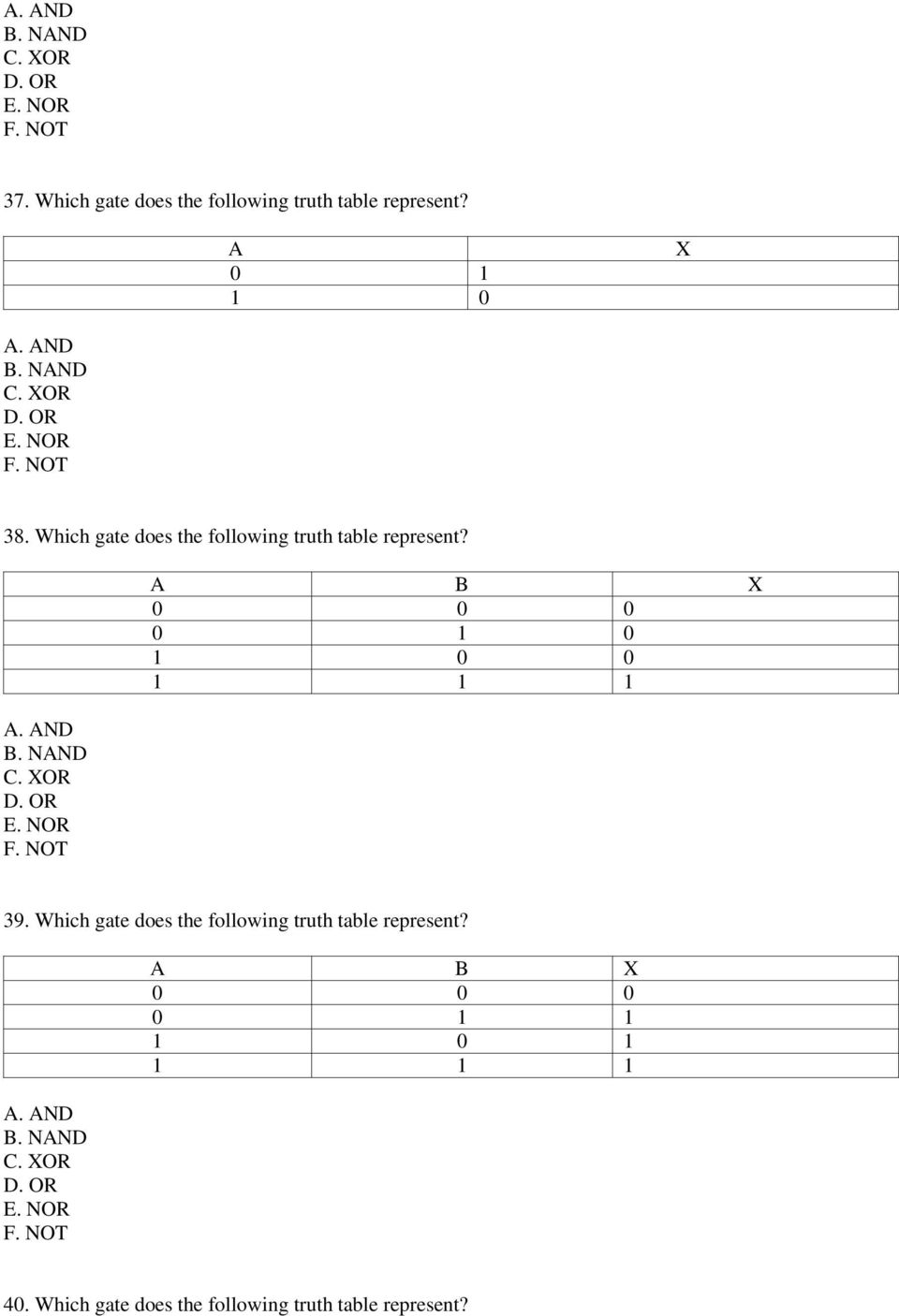
4 37. Which gate does the following truth table represent? A X 38. Which gate does the following truth table represent? A B X Which gate does the following truth table represent? A B X Which gate does the following truth table represent?
5 A B X Which gate does the following truth table represent? A B X Which gate does the following truth table represent? A B X Which gate does the following Boolean expression represent? X = A'

6 44. Which gate does the following Boolean expression represent? X = A B 45. Which gate does the following Boolean expression represent? X = A + B 46. Which gate does the following Boolean expression represent? X = A B 47. Which gate does the following Boolean expression represent? X = (A B)' 48. Which gate does the following Boolean expression represent? X = (A + B)'
' 48.")
7 49. Which gate inverts its input? 50. Which gate produces a 1 only if all its inputs are 1 and a 0 otherwise? 51. Which gate produces a 0 only if all its inputs are 0 and a 1 otherwise? 52. Which gate produces a 0 only if all its inputs are the same and a 1 otherwise? 53. Which gate produces a 0 if all its inputs are 1 and a 1 otherwise? 54. Which gate produces a 1 if all its inputs are 0 and a 0 otherwise?

8 55. How many possible input combinations exist for an OR gate with three inputs? A. 2 B. 4 C. 8 D. 16 E Generally, how many possible input combinations exist for a gate with n inputs? A. 2n B. n + 1 C. 4n D. 4n - 2 E. 2 n 57. A transistor is made up of what kind of material? A. semiconductor B. conductor C. insulation D. rubber E. copper 58. A transistor acts like which of the following? A. a light B. a button C. a switch D. a frame E. a memory location 59. If the input to a transistor (its base signal) is low, what is its output? A. binary 0 B. binary 1 C. 0 volts D. 15 volts E. ground 60. Which of the following determines the output of a combinational circuit? A. its input values only B. its input values and the current state of the circuit C. its input values and the source signal D. its input values and the carry value E. its input values and the select signal 61. Which of the following determines the output of a sequential circuit? A. its input values only

9 B. its input values and the current state of the circuit C. its input values and the source signal D. its input values and the carry value E. its input values and the select signal 62. Under what circumstances are two circuits considered equivalent? A. their input values are the same B. the output of one is the inverse of the output of the other C. their output values are the same for all possible input combinations D. their output values are always 1 E. the input of one matches the output of the other 63. The following equation is an example of which Boolean algebra property? AB = BA A. commutative B. associative C. distributive D. identity E. complement F. DeMorgan's law 64. The following equation is an example of which Boolean algebra property? (AB)C = A(BC) A. commutative B. associative C. distributive D. identity E. complement F. DeMorgan's law 65. The following equation is an example of which Boolean algebra property? A(B+C) = (AB) + (AC) A. commutative B. associative C. distributive D. identity E. complement F. DeMorgan's law 66. The following equation is an example of which Boolean algebra property? A1 = A A. commutative B. associative

10 C. distributive D. identity E. complement F. DeMorgan's law 67. The following equation is an example of which Boolean algebra property? A(A') = 0 A. commutative B. associative C. distributive D. identity E. complement F. DeMorgan's law 68. The following equation is an example of which Boolean algebra property? (AB)' = A' + B' A. commutative B. associative C. distributive D. identity E. complement F. DeMorgan's law 69. Which gate produces the sum portion of two binary digits in a half adder? A. NOT B. AND C. OR D. XOR E. NAND F. NOR 70. Which gate produces the carry portion of two binary digits in a half adder? A. NOT B. AND C. OR D. XOR E. NAND F. NOR 71. A multiplexer (or mux) does which of the following? A. adds two binary digits, taking the carry value into account B. acts as a memory circuit for a single binary digit C. contains multiple S-R latch circuits D. selects a single output value from a set of input values E. merges multiple input values into a single output value
 does which of the following? A. adds two binary digits, taking the carry value into account B. acts as a memory circuit for a single binary digit C.")
11 72. An S-R latch does which of the following? A. adds two binary digits, taking the carry value into account B. acts as a memory circuit for a single binary digit C. contains multiple S-R latch circuits D. selects a single output value from a set of input values E. merges multiple input values into a single output value 73. A VLSI chip contains how many gates? A. 0 B. 2 C. 1 to 10 D. 10 to 100 E. 100 to 100,000 F. more than 100, The central processing unit of a computer is which of the following? A. gate B. stand-alone circuit C. integrated circuit D. S-R latch E. multiplexer F. full adder 75. A is a device that performs a basic operation on electrical signals. 76. expressions can be used to describe the behavior of gates and circuits. 77. diagrams can be used to describe the behavior of gates and circuits. 78. tables can be used to describe the behavior of gates and circuits. 79. A defines the function of a gate by listing all possible input combinations for the gate and the corresponding output. 80. A gate produces the inverse of its single input. 81. The circle that's part of the logic diagram symbol for a NOT gate is called a(n) bubble. 82. A gate that accepts two input values has possible input combinations. 83. An gate produces an output of 1 only if both input values are An gate produces an output of 0 only if both input values are The Boolean expression A B represents a gate. 86. The XOR gate is also referred to as a(n) OR gate. 87. The OR and XOR gates produce different values only when both inputs are.

12 88. The gate that produces the opposite results of an AND gate is called a gate. 89. A acts as either conducts or blocks the flow of electricity, based on an input value 90. A acts like a switch, even though it has no moving parts. 91. In a circuit, the input values explicitly determine the output. 92. In a circuit, the output is determined by the input as well as the existing state of the circuit. 93. Two circuits are considered to be if they produce the same output for each input value combination. 94. The equation A(B+C) = (AB)+(AC) represents the property (or law) of AND gates. 95. The equation (AB)' = A' + B' represents the property (or law) of AND gates. 96. A circuit that produces the sum of two binary digits, taking the carry bit into account, is called a(n). 97. A is a circuit that selects a single output value from a set of inputs based on select signals 98. An S-R latch is a circuit that can be used as. 99. A circuit has multiple gates embedded into it A chip contains more than 100,000 gates What three notations can be used to describe the behavior of gates and circuits? 102. Compare the output of an AND gate and a NAND gate How is an exclusive OR gate different than a regular OR gate? 104. Draw the truth table for a NOT gate Draw the truth table for an AND gate Draw the truth table for an OR gate.
 = (AB)+(AC) represents the property (or law) of AND gates. 95.")
13 107. Draw the truth table for an XOR gate Draw the truth table for a NAND gate Draw the truth table for a NOR gate What is the relationship between the number of inputs a gate has and the size of the truth table that describes it What is a transistor? 112. How many transistors does it take to create a NOT gate? A NAND gate? An AND gate? 113. Give the Boolean expression for the following circuit diagram Draw the truth table for the following circuit diagram Give the Boolean expression for the following circuit diagram.

14 116. Draw the truth table for the following circuit diagram Give the Boolean expression for the following circuit diagram Draw the truth table for the following circuit diagram Give the Boolean expression for the following circuit diagram Draw the truth table for the following circuit diagram.

15 121. Give the Boolean expression for the following circuit diagram Draw the truth table for the following circuit diagram Give the Boolean expression for the following circuit diagram Give the Boolean expression for the following circuit diagram.

16 125. Draw a circuit diagram for the following truth table. A B AB A+B AB + (A+B) Draw a circuit diagram for the following truth table. A B A AB A (AB) Draw a circuit diagram for the following truth table. A B C A B C A (B C)
 0 0 1 0 1 0 1 1 0 1 1 0 0 0 0 1 1 0 1 1 127.")
17 128. Draw a circuit diagram for the following truth table. A B C AB (BC) C (AB+C ) (BC) + (AB+C ) Draw the logic diagram for a half adder Draw the logic diagram for a full adder What is a half adder? 132. What is a multiplexer?

18 133. What is an integrated circuit? Essay-type questions 134. Describe the three notations used to describe the behavior of gates and circuits Compare and contrast an OR gate and an XOR gate Explain how a transistor is used to create a gate Explain the concept of circuit equivalence Describe in your own words the processing of a half adder How can a VLSI chip have over 100,000 gates on it, but still have a reasonably small number of pins? 140. Describe in your own words the issues related to conflict of interest Describe in your own words the issues related to intellectual property.

19 Answers 1. True or False? A voltage level in the range 0 to 2 volts is interpreted as a binary 1. Answer: False 2. True or False? A gate is a device that accepts a single input signal and produces one or more output signals. Answer: False 3. True or False? A circuit is a combination of gates designed to accomplish a more complex logical function. Answer: True 4. True or False? A logic diagram and a truth table are equally powerful techniques for describing the behavior of a circuit. Answer: True 5. True or False? A NOT gate allows only one of its two input values to pass. Answer: False 6. True or False? The inversion bubble of an AND gate causes its input to be reversed. Answer: False 7. True or False? An AND gate and an OR gate produce opposite output. Answer: False 8. True or False? An OR gate produces a 0 output only if its two input values are 0. Answer: True 9. True or False? The OR and XOR gates produce different outputs in only one case. Answer: True

20 10. True or False? An OR gate is sometimes referred to as an inclusive OR. Answer: True 11. True or False? A NAND gate and a AND gate produce opposite output. Answer: True 12. True or False? A NAND gate and a NOR gate produce opposite output. Answer: False 13. True or False? A gate with three inputs has 8 possible input combinations. Answer: True 14. True or False? A gate is constructed of one or more transistors. Answer: True 15. True or False? A transistor is made of material that acts as a good insulator, such as rubber. Answer: False 16. True or False? If an electrical signal is grounded, the electricity literally flows harmlessly to the ground. Answer: True 17. True or False? A NOT gate can be made from a single transistor. Answer: True 18. True or False? In a sequential circuit, the output is determined solely by the input values. Answer: False

21 19. True or False? Two different circuits cannot produce the same output given the same input. Answer: False 20. True or False? Boolean algebra allows us to apply provable mathematical principles to the design of circuits. Answer: True 21. True or False? DeMorgan's law states that inverting the output of an AND gate is equivalent to inverting the individual input signals and then passing them through an OR gate. Answer: True 22. True or False? A circuit can be used to add two binary digits together and produce a carry bit. Answer: True 23. True or False? A multiplexer produces multiple outputs for each input. Answer: False 24. True or False? A circuit cannot be used as memory because input signals are lost as soon as they pass through a gate. Answer: False 25. True or False? A single integrated circuit can have more than 100,000 gates on it. Answer: True 26. True or False? The central processing unit (CPU) of a computer is often a single integrated circuit. Answer: True Multiple Choice
22 27. Which of the following is a device that performs a basic operation on electrical signals? A. logic symbol B. truth table C. gate D. circuit E. S-R latch Answer: C 28. Which of the following lists all possible input combinations for a gate, and the corresponding output? A. truth table B. Boolean expression C. logic diagram D. circuit E. S-R latch Answer: A 29. The circle in the logic symbol of a NOT gate is known as what? A. combinational circuit B. sequential circuit C. completion sphere D. inversion bubble E. NAND gate Answer: D 30. What is a regular OR gate also known as? A. exclusive OR B. inclusive OR C. repetitive OR D. completion OR E. inversion OR Answer: B 31. Which gate does the following logic symbol represent?
23 Answer: F 32. Which gate does the following logic symbol represent? Answer: A 33. Which gate does the following logic symbol represent? Answer: D 34. Which gate does the following logic symbol represent? Answer: C 35. Which gate does the following logic symbol represent?
24 Answer: B 36. Which gate does the following logic symbol represent? Answer: E 37. Which gate does the following truth table represent? A X Answer: F 38. Which gate does the following truth table represent?
25 A B X Answer: A 39. Which gate does the following truth table represent? Answer: D A B X Which gate does the following truth table represent? Answer: C A B X
26 41. Which gate does the following truth table represent? Answer: B A B X Which gate does the following truth table represent? Answer: E A B X Which gate does the following Boolean expression represent? X = A' Answer: F 44. Which gate does the following Boolean expression represent? X = A B
27 Answer: A 45. Which gate does the following Boolean expression represent? X = A + B Answer: D 46. Which gate does the following Boolean expression represent? X = A B Answer: C 47. Which gate does the following Boolean expression represent? X = (A B)' Answer: B
28 48. Which gate does the following Boolean expression represent? X = (A + B)' Answer: E 49. Which gate inverts its input? Answer: F 50. Which gate produces a 1 only if all its inputs are 1 and a 0 otherwise? Answer: A 51. Which gate produces a 0 only if all its inputs are 0 and a 1 otherwise? Answer: D 52. Which gate produces a 0 only if all its inputs are the same and a 1 otherwise?
29 Answer: C 53. Which gate produces a 0 if all its inputs are 1 and a 1 otherwise? Answer: B 54. Which gate produces a 1 if all its inputs are 0 and a 0 otherwise? Answer: E 55. How many possible input combinations exist for an OR gate with three inputs? A. 2 B. 4 C. 8 D. 16 E. 32 Answer: C 56. Generally, how many possible input combinations exist for a gate with n inputs? A. 2n B. n + 1 C. 4n D. 4n - 2 E. 2 n Answer: E 57. A transistor is made up of what kind of material? A. semiconductor
30 B. conductor C. insulation D. rubber E. copper Answer: A 58. A transistor acts like which of the following? A. a light B. a button C. a switch D. a frame E. a memory location Answer: C 59. If the input to a transistor (its base signal) is low, what is its output? A. binary 0 B. binary 1 C. 0 volts D. 15 volts E. ground Answer: B 60. Which of the following determines the output of a combinational circuit? A. its input values only B. its input values and the current state of the circuit C. its input values and the source signal D. its input values and the carry value E. its input values and the select signal Answer: A 61. Which of the following determines the output of a sequential circuit? A. its input values only B. its input values and the current state of the circuit C. its input values and the source signal D. its input values and the carry value E. its input values and the select signal Answer: B 62. Under what circumstances are two circuits considered equivalent? A. their input values are the same B. the output of one is the inverse of the output of the other
31 C. their output values are the same for all possible input combinations D. their output values are always 1 E. the input of one matches the output of the other Answer: B 63. The following equation is an example of which Boolean algebra property? AB = BA A. commutative B. associative C. distributive D. identity E. complement F. DeMorgan's law Answer: A 64. The following equation is an example of which Boolean algebra property? (AB)C = A(BC) A. commutative B. associative C. distributive D. identity E. complement F. DeMorgan's law Answer: B 65. The following equation is an example of which Boolean algebra property? A(B+C) = (AB) + (AC) A. commutative B. associative C. distributive D. identity E. complement F. DeMorgan's law Answer: C 66. The following equation is an example of which Boolean algebra property? A1 = A
32 A. commutative B. associative C. distributive D. identity E. complement F. DeMorgan's law Answer: D 67. The following equation is an example of which Boolean algebra property? A(A') = 0 A. commutative B. associative C. distributive D. identity E. complement F. DeMorgan's law Answer: E 68. The following equation is an example of which Boolean algebra property? (AB)' = A' + B' A. commutative B. associative C. distributive D. identity E. complement F. DeMorgan's law Answer: F 69. Which gate produces the sum portion of two binary digits in a half adder? A. NOT B. AND C. OR D. XOR E. NAND F. NOR Answer: D 70. Which gate produces the carry portion of two binary digits in a half adder? A. NOT
33 B. AND C. OR D. XOR E. NAND F. NOR Answer: B 71. A multiplexer (or mux) does which of the following? A. adds two binary digits, taking the carry value into account B. acts as a memory circuit for a single binary digit C. contains multiple S-R latch circuits D. selects a single output value from a set of input values E. merges multiple input values into a single output value Answer: D 72. An S-R latch does which of the following? A. adds two binary digits, taking the carry value into account B. acts as a memory circuit for a single binary digit C. contains multiple S-R latch circuits D. selects a single output value from a set of input values E. merges multiple input values into a single output value Answer: B 73. A VLSI chip contains how many gates? A. 0 B. 2 C. 1 to 10 D. 10 to 100 E. 100 to 100,000 F. more than 100,000 Answer: F 74. The central processing unit of a computer is which of the following? A. gate B. stand-alone circuit C. integrated circuit D. S-R latch E. multiplexer F. full adder Answer: C
34 Fill-in-the-Blank 75. A is a device that performs a basic operation on electrical signals. Answer: Gate 76. expressions can be used to describe the behavior of gates and circuits. Answer: Boolean 77. diagrams can be used to describe the behavior of gates and circuits. Answer: Logic 78. tables can be used to describe the behavior of gates and circuits. Answer: Truth 79. A defines the function of a gate by listing all possible input combinations for the gate and the corresponding output. Answer: truth table 80. A gate produces the inverse of its single input. Answer: NOT 81. The circle that's part of the logic diagram symbol for a NOT gate is called a(n) bubble. Answer: Inversion 82. A gate that accepts two input values has possible input combinations. Answer: Four 83. An gate produces an output of 1 only if both input values are 1.
35 Answer: AND 84. An gate produces an output of 0 only if both input values are 0. Answer: OR 85. The Boolean expression A B represents a gate. Answer: XOR 86. The XOR gate is also referred to as a(n) OR gate. Answer: Exclusive 87. The OR and XOR gates produce different values only when both inputs are. Answer: The gate that produces the opposite results of an AND gate is called a gate. Answer: NAND 89. A acts as either conducts or blocks the flow of electricity, based on an input value Answer: Transistor 90. A acts like a switch, even though it has no moving parts. Answer: Transistor 91. In a circuit, the input values explicitly determine the output. Answer: Combinational 92. In a circuit, the output is determined by the input as well as the existing state of the circuit. Answer: Sequential
36 93. Two circuits are considered to be if they produce the same output for each input value combination. Answer: Equivalent 94. The equation A(B+C) = (AB)+(AC) represents the property (or law) of AND gates. Answer: Distributive 95. The equation (AB)' = A' + B' represents the property (or law) of AND gates. Answer: DeMorgan's 96. A circuit that produces the sum of two binary digits, taking the carry bit into account, is called a(n). Answer: Adder 97. A is a circuit that selects a single output value from a set of inputs based on select signals Answer: Multiplexer 98. An S-R latch is a circuit that can be used as. Answer: Memory 99. A circuit has multiple gates embedded into it. Answer: Integrated 100. A chip contains more than 100,000 gates. Answer: VLSI, or Very-Large-Scale Integration Short Answer
37 101. What three notations can be used to describe the behavior of gates and circuits? Answer: Boolean expressions, logic diagrams, and truth tables 102. Compare the output of an AND gate and a NAND gate. Answer: The output of an AND gate is 1 only if both inputs are 1. A NAND gate produces the exact opposite output How is an exclusive OR gate different than a regular OR gate? Answer: The output of the two gates is identical except when both input values are 1, in which case an OR gate produces a 1 but an exclusive OR produces a Draw the truth table for a NOT gate. Answer: 105. Draw the truth table for an AND gate. Answer: 106. Draw the truth table for an OR gate. Answer:
38 107. Draw the truth table for an XOR gate. Answer: 108. Draw the truth table for a NAND gate. Answer: 109. Draw the truth table for a NOR gate. Answer: 110. What is the relationship between the number of inputs a gate has and the size of the truth table that describes it. Answer: There are 2 n possible input combinations for a gate with n inputs, so there are 2 n rows in the truth table that describes it What is a transistor? Answer: A transistor is a device that acts like a switch, either allowing electricity to flow or blocking it, depending on the voltage level of its input signal How many transistors does it take to create a NOT gate? A NAND gate? An AND gate? Answer: It takes one transistor to make a NOT gate, two to make a NAND gate, and three to make an AND gate.
39 113. Give the Boolean expression for the following circuit diagram. Answer: (A B)' 114. Draw the truth table for the following circuit diagram. Answer: 115. Give the Boolean expression for the following circuit diagram. Answer: (A+B) B' 116. Draw the truth table for the following circuit diagram.
40 Answer: 117. Give the Boolean expression for the following circuit diagram. Answer: (AB) + C 118. Draw the truth table for the following circuit diagram. Answer: 119. Give the Boolean expression for the following circuit diagram.
41 Answer: (A+B)(B+C) 120. Draw the truth table for the following circuit diagram. Answer: 121. Give the Boolean expression for the following circuit diagram.
42 Answer: A'B + (B+C)' 122. Draw the truth table for the following circuit diagram. Answer: 123. Give the Boolean expression for the following circuit diagram. Answer: (AB + C)D 124. Give the Boolean expression for the following circuit diagram.
43 Answer: (AB)' + (CD)' 125. Draw a circuit diagram for the following truth table. Answer: A B AB A+B AB + (A+B) Draw a circuit diagram for the following truth table. Answer: A B A AB A (AB) Draw a circuit diagram for the following truth table.
44 Answer: A B C A B C A (B C) Draw a circuit diagram for the following truth table. A B C AB (BC) C (AB+C ) (BC) + (AB+C ) Answer: 129. Draw the logic diagram for a half adder.
45 Answer: 130. Draw the logic diagram for a full adder. Answer: 131. What is a half adder? Answer: A half adder s a circuit that computes the sum of two bits and produces the appropriate carry bit What is a multiplexer? Answer: A multiplexer is a circuit that uses input control signals to determine which of several data input lines is to be routed to the output What is an integrated circuit? Answer: An integrated circuit, or chip, is a piece of silicon on which multiple gates have been embedded. Essay
46 134. Describe the three notations used to describe the behavior of gates and circuits. Answer: Boolean expressions represent the behavior of a gate or circuit using equations with logical operators. Based in Boolean algebra, these equations can be manipulated in formal, mathematical ways. Logic diagrams are a graphical representation of a circuit. Using special symbols for each type of gate, a circuit can be represented by connecting the output of one gate to the input of another. Truth tables list all possible input combinations to a circuit and the corresponding output. Columns in a truth table might be used to show the intermediate results of circuit processing Compare and contrast an OR gate and an XOR gate. Answer: An OR gate produces an output of 1 if either or both input values are 1. Therefore, an OR gate produces an output of 0 only in one situation, when both input values are 0. An XOR gate, which stands for exclusive OR, produces an output of 1 if either input is 1, but not if both inputs are 1 at the same time. So an XOR gate produces identical output to an OR gate except in the case when both input values are 1. An XOR gate produces an output 0 in two situations, when both input values are 0 and when both input values are Explain how a transistor is used to create a gate. Answer: A transistor has an input line, an output line, a grounded emitter, and an electrical source. If the input signal is high, the source is grounded and the output is low. If the input signal is low, the source is not grounded and the output is high. Thus, a single transistor acts as a NOT gate, inversing it's input signal. Using two transistors, its possible to construct NAND and NOR gates. Using a third transistor to reverse the output of the NAND and NOR gates, its possible to construct AND and OR gates Explain the concept of circuit equivalence. Answer: Two circuits are considered to be equivalent if they produce the same output for all possible input combinations. That is, two different circuits, made up of different gates and connections, can be equivalent in the function they perform. When designing a circuit, its often cost effective to minimize the number of components that make up a circuit, as long as it produces the desired result Describe the processing of a half adder. Answer: A half adder is a circuit that produces two outputs, the sum bit and the carry bit. The two input binary digits are passed through an XOR gate to produce the sum, and the same input bits are passed through an AND gate to produce the carry. The extra digit is needed only when both inputs are 1. When that occurs, the XOR gate produces a sum bit of zero and the AND gate produces a carry bit of 1. In all other cases, the carry bit will be How can a VLSI chip have over 100,000 gates on it, but still have a reasonably small number of pins? Answer: An SSI chip has only a few gates on it, and so it is reasonable to have pins corresponding to every input and output value for each gate. But a VLSI chip, with over 100,000 gates, cannot have pins corresponding to each gate. Instead, a VLSI chip is designed to contain a circuit made up of thousands of
47 gates, but using only a few input and output values. Instead of providing the functionality of several gates on one chip, it provides the functionality of one complex circuit Describe in your own words the issues related to conflict of interest. Answer: see p.111 of text 141. Describe in your own words the issues related to intellectual property. Answer: see p.111 of text
Gates, Circuits, and Boolean Algebra
 Gates, Circuits, and Boolean Algebra Computers and Electricity A gate is a device that performs a basic operation on electrical signals Gates are combined into circuits to perform more complicated tasks
Basic Logic Gates Richard E. Haskell
 BASIC LOGIC GATES 1 E Basic Logic Gates Richard E. Haskell All digital systems are made from a few basic digital circuits that we call logic gates. These circuits perform the basic logic functions that
Digital Logic Design. Basics Combinational Circuits Sequential Circuits. Pu-Jen Cheng
 Digital Logic Design Basics Combinational Circuits Sequential Circuits Pu-Jen Cheng Adapted from the slides prepared by S. Dandamudi for the book, Fundamentals of Computer Organization and Design. Introduction
ENGI 241 Experiment 5 Basic Logic Gates
 ENGI 24 Experiment 5 Basic Logic Gates OBJECTIVE This experiment will examine the operation of the AND, NAND, OR, and NOR logic gates and compare the expected outputs to the truth tables for these devices.
CHAPTER 3 Boolean Algebra and Digital Logic
 CHAPTER 3 Boolean Algebra and Digital Logic 3.1 Introduction 121 3.2 Boolean Algebra 122 3.2.1 Boolean Expressions 123 3.2.2 Boolean Identities 124 3.2.3 Simplification of Boolean Expressions 126 3.2.4
Digital circuits make up all computers and computer systems. The operation of digital circuits is based on
 Digital Logic Circuits Digital circuits make up all computers and computer systems. The operation of digital circuits is based on Boolean algebra, the mathematics of binary numbers. Boolean algebra is
Binary Adders: Half Adders and Full Adders
 Binary Adders: Half Adders and Full Adders In this set of slides, we present the two basic types of adders: 1. Half adders, and 2. Full adders. Each type of adder functions to add two binary bits. In order
MULTIPLE CHOICE. Choose the one alternative that best completes the statement or answers the question.
 CHAPTER3 QUESTIONS MULTIPLE CHOICE. Choose the one alternative that best completes the statement or answers the question. ) If one input of an AND gate is LOW while the other is a clock signal, the output
Lecture 5: Gate Logic Logic Optimization
 Lecture 5: Gate Logic Logic Optimization MAH, AEN EE271 Lecture 5 1 Overview Reading McCluskey, Logic Design Principles- or any text in boolean algebra Introduction We could design at the level of irsim
BOOLEAN ALGEBRA & LOGIC GATES
 BOOLEAN ALGEBRA & LOGIC GATES Logic gates are electronic circuits that can be used to implement the most elementary logic expressions, also known as Boolean expressions. The logic gate is the most basic
United States Naval Academy Electrical and Computer Engineering Department. EC262 Exam 1
 United States Naval Academy Electrical and Computer Engineering Department EC262 Exam 29 September 2. Do a page check now. You should have pages (cover & questions). 2. Read all problems in their entirety.
FORDHAM UNIVERSITY CISC 3593. Dept. of Computer and Info. Science Spring, 2011. Lab 2. The Full-Adder
 FORDHAM UNIVERSITY CISC 3593 Fordham College Lincoln Center Computer Organization Dept. of Computer and Info. Science Spring, 2011 Lab 2 The Full-Adder 1 Introduction In this lab, the student will construct
Digital Electronics Detailed Outline
 Digital Electronics Detailed Outline Unit 1: Fundamentals of Analog and Digital Electronics (32 Total Days) Lesson 1.1: Foundations and the Board Game Counter (9 days) 1. Safety is an important concept
Logic in Computer Science: Logic Gates
 Logic in Computer Science: Logic Gates Lila Kari The University of Western Ontario Logic in Computer Science: Logic Gates CS2209, Applied Logic for Computer Science 1 / 49 Logic and bit operations Computers
Having read this workbook you should be able to: recognise the arrangement of NAND gates used to form an S-R flip-flop.
 Objectives Having read this workbook you should be able to: recognise the arrangement of NAND gates used to form an S-R flip-flop. describe how such a flip-flop can be SET and RESET. describe the disadvantage
Gates & Boolean Algebra. Boolean Operators. Combinational Logic. Introduction
 Introduction Gates & Boolean lgebra Boolean algebra: named after mathematician George Boole (85 864). 2-valued algebra. digital circuit can have one of 2 values. Signal between and volt =, between 4 and
NEW adder cells are useful for designing larger circuits despite increase in transistor count by four per cell.
 CHAPTER 4 THE ADDER The adder is one of the most critical components of a processor, as it is used in the Arithmetic Logic Unit (ALU), in the floating-point unit and for address generation in case of cache
Figure 8-1 Four Possible Results of Adding Two Bits
 CHPTER EIGHT Combinational Logic pplications Thus far, our discussion has focused on the theoretical design issues of computer systems. We have not yet addressed any of the actual hardware you might find
Boolean Algebra Part 1
 Boolean Algebra Part 1 Page 1 Boolean Algebra Objectives Understand Basic Boolean Algebra Relate Boolean Algebra to Logic Networks Prove Laws using Truth Tables Understand and Use First Basic Theorems
COMBINATIONAL CIRCUITS
 COMBINATIONAL CIRCUITS http://www.tutorialspoint.com/computer_logical_organization/combinational_circuits.htm Copyright tutorialspoint.com Combinational circuit is a circuit in which we combine the different
Two-level logic using NAND gates
 CSE140: Components and Design Techniques for Digital Systems Two and Multilevel logic implementation Tajana Simunic Rosing 1 Two-level logic using NND gates Replace minterm ND gates with NND gates Place
Let s put together a Manual Processor
 Lecture 14 Let s put together a Manual Processor Hardware Lecture 14 Slide 1 The processor Inside every computer there is at least one processor which can take an instruction, some operands and produce
Chapter 2 Logic Gates and Introduction to Computer Architecture
 Chapter 2 Logic Gates and Introduction to Computer Architecture 2.1 Introduction The basic components of an Integrated Circuit (IC) is logic gates which made of transistors, in digital system there are
COMBINATIONAL and SEQUENTIAL LOGIC CIRCUITS Hardware implementation and software design
 PH-315 COMINATIONAL and SEUENTIAL LOGIC CIRCUITS Hardware implementation and software design A La Rosa I PURPOSE: To familiarize with combinational and sequential logic circuits Combinational circuits
2.0 Chapter Overview. 2.1 Boolean Algebra
 Thi d t t d ith F M k 4 0 2 Boolean Algebra Chapter Two Logic circuits are the basis for modern digital computer systems. To appreciate how computer systems operate you will need to understand digital
3.Basic Gate Combinations
 3.Basic Gate Combinations 3.1 TTL NAND Gate In logic circuits transistors play the role of switches. For those in the TTL gate the conducting state (on) occurs when the baseemmiter signal is high, and
exclusive-or and Binary Adder R eouven Elbaz [email protected] Office room: DC3576
 exclusive-or and Binary Adder R eouven Elbaz [email protected] Office room: DC3576 Outline exclusive OR gate (XOR) Definition Properties Examples of Applications Odd Function Parity Generation and Checking
Understanding Logic Design
 Understanding Logic Design ppendix of your Textbook does not have the needed background information. This document supplements it. When you write add DD R0, R1, R2, you imagine something like this: R1
Combinational circuits
 Combinational circuits Combinational circuits are stateless The outputs are functions only of the inputs Inputs Combinational circuit Outputs 3 Thursday, September 2, 3 Enabler Circuit (High-level view)
ELEC 2210 - EXPERIMENT 1 Basic Digital Logic Circuits
 Objectives ELEC - EXPERIMENT Basic Digital Logic Circuits The experiments in this laboratory exercise will provide an introduction to digital electronic circuits. You will learn how to use the IDL-00 Bit
Chapter 7 Memory and Programmable Logic
 NCNU_2013_DD_7_1 Chapter 7 Memory and Programmable Logic 71I 7.1 Introduction ti 7.2 Random Access Memory 7.3 Memory Decoding 7.5 Read Only Memory 7.6 Programmable Logic Array 77P 7.7 Programmable Array
Lecture 8: Synchronous Digital Systems
 Lecture 8: Synchronous Digital Systems The distinguishing feature of a synchronous digital system is that the circuit only changes in response to a system clock. For example, consider the edge triggered
Karnaugh Maps & Combinational Logic Design. ECE 152A Winter 2012
 Karnaugh Maps & Combinational Logic Design ECE 52A Winter 22 Reading Assignment Brown and Vranesic 4 Optimized Implementation of Logic Functions 4. Karnaugh Map 4.2 Strategy for Minimization 4.2. Terminology
Digital Electronics Part I Combinational and Sequential Logic. Dr. I. J. Wassell
 Digital Electronics Part I Combinational and Sequential Logic Dr. I. J. Wassell Introduction Aims To familiarise students with Combinational logic circuits Sequential logic circuits How digital logic gates
Flip-Flops, Registers, Counters, and a Simple Processor
 June 8, 22 5:56 vra235_ch7 Sheet number Page number 349 black chapter 7 Flip-Flops, Registers, Counters, and a Simple Processor 7. Ng f3, h7 h6 349 June 8, 22 5:56 vra235_ch7 Sheet number 2 Page number
Upon completion of unit 1.1, students will be able to
 Upon completion of unit 1.1, students will be able to 1. Demonstrate safety of the individual, class, and overall environment of the classroom/laboratory, and understand that electricity, even at the nominal
Chapter 2: Boolean Algebra and Logic Gates. Boolean Algebra
 The Universit Of Alabama in Huntsville Computer Science Chapter 2: Boolean Algebra and Logic Gates The Universit Of Alabama in Huntsville Computer Science Boolean Algebra The algebraic sstem usuall used
Read-only memory Implementing logic with ROM Programmable logic devices Implementing logic with PLDs Static hazards
 Points ddressed in this Lecture Lecture 8: ROM Programmable Logic Devices Professor Peter Cheung Department of EEE, Imperial College London Read-only memory Implementing logic with ROM Programmable logic
Sistemas Digitais I LESI - 2º ano
 Sistemas Digitais I LESI - 2º ano Lesson 6 - Combinational Design Practices Prof. João Miguel Fernandes ([email protected]) Dept. Informática UNIVERSIDADE DO MINHO ESCOLA DE ENGENHARIA - PLDs (1) - The
EE 42/100 Lecture 24: Latches and Flip Flops. Rev B 4/21/2010 (2:04 PM) Prof. Ali M. Niknejad
 Prof. Ali M. Niknejad") A. M. Niknejad University of California, Berkeley EE 100 / 42 Lecture 24 p. 1/20 EE 42/100 Lecture 24: Latches and Flip Flops ELECTRONICS Rev B 4/21/2010 (2:04 PM) Prof. Ali M. Niknejad University of California,
A. M. Niknejad University of California, Berkeley EE 100 / 42 Lecture 24 p. 1/20 EE 42/100 Lecture 24: Latches and Flip Flops ELECTRONICS Rev B 4/21/2010 (2:04 PM) Prof. Ali M. Niknejad University of California,
Memory Elements. Combinational logic cannot remember
 Memory Elements Combinational logic cannot remember Output logic values are function of inputs only Feedback is needed to be able to remember a logic value Memory elements are needed in most digital logic
CS311 Lecture: Sequential Circuits
 CS311 Lecture: Sequential Circuits Last revised 8/15/2007 Objectives: 1. To introduce asynchronous and synchronous flip-flops (latches and pulsetriggered, plus asynchronous preset/clear) 2. To introduce
A single register, called the accumulator, stores the. operand before the operation, and stores the result. Add y # add y from memory to the acc
 Other architectures Example. Accumulator-based machines A single register, called the accumulator, stores the operand before the operation, and stores the result after the operation. Load x # into acc
Boolean Algebra. Boolean Algebra. Boolean Algebra. Boolean Algebra
 2 Ver..4 George Boole was an English mathematician of XIX century can operate on logic (or Boolean) variables that can assume just 2 values: /, true/false, on/off, closed/open Usually value is associated
CSE140: Midterm 1 Solution and Rubric
 CSE140: Midterm 1 Solution and Rubric April 23, 2014 1 Short Answers 1.1 True or (6pts) 1. A maxterm must include all input variables (1pt) True 2. A canonical product of sums is a product of minterms
So far we have investigated combinational logic for which the output of the logic devices/circuits depends only on the present state of the inputs.
 equential Logic o far we have investigated combinational logic for which the output of the logic devices/circuits depends only on the present state of the inputs. In sequential logic the output of the
Chapter 10 Advanced CMOS Circuits
 Transmission Gates Chapter 10 Advanced CMOS Circuits NMOS Transmission Gate The active pull-up inverter circuit leads one to thinking about alternate uses of NMOS devices. Consider the circuit shown in
Content Map For Career & Technology
 Content Strand: Applied Academics CT-ET1-1 analysis of electronic A. Fractions and decimals B. Powers of 10 and engineering notation C. Formula based problem solutions D. Powers and roots E. Linear equations
Gates. J. Robert Jump Department of Electrical And Computer Engineering Rice University Houston, TX 77251
 Gates J. Robert Jump Department of Electrical And Computer Engineering Rice University Houston, T 77251 1. The Evolution of Electronic Digital Devices...1 2. Logical Operations and the Behavior of Gates...2
CSE140: Components and Design Techniques for Digital Systems
 CSE4: Components and Design Techniques for Digital Systems Tajana Simunic Rosing What we covered thus far: Number representations Logic gates Boolean algebra Introduction to CMOS HW#2 due, HW#3 assigned
Lecture 12: More on Registers, Multiplexers, Decoders, Comparators and Wot- Nots
 Lecture 12: More on Registers, Multiplexers, Decoders, Comparators and Wot- Nots Registers As you probably know (if you don t then you should consider changing your course), data processing is usually
Mixed Logic A B A B. 1. Ignore all bubbles on logic gates and inverters. This means
 Mixed Logic Introduction Mixed logic is a gate-level design methodology used in industry. It allows a digital logic circuit designer the functional description of the circuit from its physical implementation.
Simplifying Logic Circuits with Karnaugh Maps
 Simplifying Logic Circuits with Karnaugh Maps The circuit at the top right is the logic equivalent of the Boolean expression: f = abc + abc + abc Now, as we have seen, this expression can be simplified
Voltage, Current, Resistance, Capacitance and Inductance
 Voltage, Current, Resistance, Capacitance and Inductance Really basic electrical engineering. 1 Electricity and conductors Electricity is the movement of electrons. Electrons move easily through a conductor
Digital Logic Elements, Clock, and Memory Elements
 Physics 333 Experiment #9 Fall 999 Digital Logic Elements, Clock, and Memory Elements Purpose This experiment introduces the fundamental circuit elements of digital electronics. These include a basic set
CSE140: Components and Design Techniques for Digital Systems. Introduction. Prof. Tajana Simunic Rosing
 CSE4: Components and Design Techniques for Digital Systems Introduction Prof. Tajana Simunic Rosing Welcome to CSE 4! Instructor: Tajana Simunic Rosing Email: [email protected]; please put CSE4 in the subject
CHAPTER 2. Logic. 1. Logic Definitions. Notation: Variables are used to represent propositions. The most common variables used are p, q, and r.
 CHAPTER 2 Logic 1. Logic Definitions 1.1. Propositions. Definition 1.1.1. A proposition is a declarative sentence that is either true (denoted either T or 1) or false (denoted either F or 0). Notation:
Unit 3 Boolean Algebra (Continued)
") Unit 3 Boolean Algebra (Continued) 1. Exclusive-OR Operation 2. Consensus Theorem Department of Communication Engineering, NCTU 1 3.1 Multiplying Out and Factoring Expressions Department of Communication
Unit 3 Boolean Algebra (Continued) 1. Exclusive-OR Operation 2. Consensus Theorem Department of Communication Engineering, NCTU 1 3.1 Multiplying Out and Factoring Expressions Department of Communication
Here we introduced (1) basic circuit for logic and (2)recent nano-devices, and presented (3) some practical issues on nano-devices.
 basic circuit for logic and (2)recent nano-devices, and presented (3) some practical issues on nano-devices.") Outline Here we introduced () basic circuit for logic and (2)recent nano-devices, and presented (3) some practical issues on nano-devices. Circuit Logic Gate A logic gate is an elemantary building block
Outline Here we introduced () basic circuit for logic and (2)recent nano-devices, and presented (3) some practical issues on nano-devices. Circuit Logic Gate A logic gate is an elemantary building block
SEQUENTIAL CIRCUITS. Block diagram. Flip Flop. S-R Flip Flop. Block Diagram. Circuit Diagram
 SEQUENTIAL CIRCUITS http://www.tutorialspoint.com/computer_logical_organization/sequential_circuits.htm Copyright tutorialspoint.com The combinational circuit does not use any memory. Hence the previous
ECE410 Design Project Spring 2008 Design and Characterization of a CMOS 8-bit Microprocessor Data Path
 ECE410 Design Project Spring 2008 Design and Characterization of a CMOS 8-bit Microprocessor Data Path Project Summary This project involves the schematic and layout design of an 8-bit microprocessor data
Adder.PPT(10/1/2009) 5.1. Lecture 13. Adder Circuits
 5.1. Lecture 13. Adder Circuits") Adder.T(//29) 5. Lecture 3 Adder ircuits Objectives Understand how to add both signed and unsigned numbers Appreciate how the delay of an adder circuit depends on the data values that are being added together
Adder.T(//29) 5. Lecture 3 Adder ircuits Objectives Understand how to add both signed and unsigned numbers Appreciate how the delay of an adder circuit depends on the data values that are being added together
Karnaugh Maps. Circuit-wise, this leads to a minimal two-level implementation
 Karnaugh Maps Applications of Boolean logic to circuit design The basic Boolean operations are AND, OR and NOT These operations can be combined to form complex expressions, which can also be directly translated
Programming Logic controllers
 Programming Logic controllers Programmable Logic Controller (PLC) is a microprocessor based system that uses programmable memory to store instructions and implement functions such as logic, sequencing,
Systems I: Computer Organization and Architecture
 Systems I: Computer Organization and Architecture Lecture 9 - Register Transfer and Microoperations Microoperations Digital systems are modular in nature, with modules containing registers, decoders, arithmetic
CHAPTER 11 LATCHES AND FLIP-FLOPS
 CHAPTER 11 LATCHES AND FLIP-FLOPS This chapter in the book includes: Objectives Study Guide 11.1 Introduction 11.2 Set-Reset Latch 11.3 Gated D Latch 11.4 Edge-Triggered D Flip-Flop 11.5 S-R Flip-Flop
ANALOG & DIGITAL ELECTRONICS
 ANALOG & DIGITAL ELECTRONICS Course Instructor: Course No: PH-218 3-1-0-8 Dr. A.P. Vajpeyi E-mail: [email protected] Room No: #305 Department of Physics, Indian Institute of Technology Guwahati,
CHAPTER 11: Flip Flops
 CHAPTER 11: Flip Flops In this chapter, you will be building the part of the circuit that controls the command sequencing. The required circuit must operate the counter and the memory chip. When the teach
Circuits and Boolean Expressions
 Circuits and Boolean Expressions Provided by TryEngineering - Lesson Focus Boolean logic is essential to understanding computer architecture. It is also useful in program construction and Artificial Intelligence.
Chapter 4 Register Transfer and Microoperations. Section 4.1 Register Transfer Language
 Chapter 4 Register Transfer and Microoperations Section 4.1 Register Transfer Language Digital systems are composed of modules that are constructed from digital components, such as registers, decoders,
Decimal Number (base 10) Binary Number (base 2)
 Binary Number (base 2)") LECTURE 5. BINARY COUNTER Before starting with counters there is some vital information that needs to be understood. The most important is the fact that since the outputs of a digital chip can only be
LECTURE 5. BINARY COUNTER Before starting with counters there is some vital information that needs to be understood. The most important is the fact that since the outputs of a digital chip can only be
Bipolar Junction Transistor Basics
 by Kenneth A. Kuhn Sept. 29, 2001, rev 1 Introduction A bipolar junction transistor (BJT) is a three layer semiconductor device with either NPN or PNP construction. Both constructions have the identical
SECTION C [short essay] [Not to exceed 120 words, Answer any SIX questions. Each question carries FOUR marks] 6 x 4=24 marks
![SECTION C [short essay] [Not to exceed 120 words, Answer any SIX questions. Each question carries FOUR marks] 6 x 4=24 marks](/thumbs/35/17285180.jpg "SECTION C [short essay] [Not to exceed 120 words, Answer any SIX questions. Each question carries FOUR marks] 6 x 4=24 marks") UNIVERSITY OF KERALA First Degree Programme in Computer Applications Model Question Paper Semester I Course Code- CP 1121 Introduction to Computer Science TIME : 3 hrs Maximum Mark: 80 SECTION A [Very
UNIVERSITY OF KERALA First Degree Programme in Computer Applications Model Question Paper Semester I Course Code- CP 1121 Introduction to Computer Science TIME : 3 hrs Maximum Mark: 80 SECTION A [Very
CSE140 Homework #7 - Solution
 CSE140 Spring2013 CSE140 Homework #7 - Solution You must SHOW ALL STEPS for obtaining the solution. Reporting the correct answer, without showing the work performed at each step will result in getting
Combinational Logic Design
 Chapter 4 Combinational Logic Design The foundations for the design of digital logic circuits were established in the preceding chapters. The elements of Boolean algebra (two-element switching algebra
Introduction to Digital Logic with Laboratory Exercises
 Introduction to Digital Logic with Laboratory Exercises Introduction to Digital Logic with Laboratory Exercises James Feher Copyright 29 James Feher Editor-In-Chief: James Feher Associate Editor: Marisa
Logic Reference Guide
 Logic eference Guide Advanced Micro evices INTOUCTION Throughout this data book and design guide we have assumed that you have a good working knowledge of logic. Unfortunately, there always comes a time
6. BOOLEAN LOGIC DESIGN
 6. OOLEN LOGI DESIGN 89 Topics: oolean algebra onverting between oolean algebra and logic gates and ladder logic Logic examples Objectives: e able to simplify designs with oolean algebra 6. INTRODUTION
Lab 1: Full Adder 0.0
 Lab 1: Full Adder 0.0 Introduction In this lab you will design a simple digital circuit called a full adder. You will then use logic gates to draw a schematic for the circuit. Finally, you will verify
Properties of Real Numbers
 16 Chapter P Prerequisites P.2 Properties of Real Numbers What you should learn: Identify and use the basic properties of real numbers Develop and use additional properties of real numbers Why you should
Design and Development of Virtual Instrument (VI) Modules for an Introductory Digital Logic Course
 Modules for an Introductory Digital Logic Course") Session ENG 206-6 Design and Development of Virtual Instrument (VI) Modules for an Introductory Digital Logic Course Nikunja Swain, Ph.D., PE South Carolina State University [email protected] Raghu Korrapati,
Session ENG 206-6 Design and Development of Virtual Instrument (VI) Modules for an Introductory Digital Logic Course Nikunja Swain, Ph.D., PE South Carolina State University [email protected] Raghu Korrapati,
Study Guide for the Electronics Technician Pre-Employment Examination
 Bay Area Rapid Transit District Study Guide for the Electronics Technician Pre-Employment Examination INTRODUCTION The Bay Area Rapid Transit (BART) District makes extensive use of electronics technology
MICROPROCESSOR. Exclusive for IACE Students www.iace.co.in iacehyd.blogspot.in Ph: 9700077455/422 Page 1
 MICROPROCESSOR A microprocessor incorporates the functions of a computer s central processing unit (CPU) on a single Integrated (IC), or at most a few integrated circuit. It is a multipurpose, programmable
DEPARTMENT OF INFORMATION TECHNLOGY
 DRONACHARYA GROUP OF INSTITUTIONS, GREATER NOIDA Affiliated to Mahamaya Technical University, Noida Approved by AICTE DEPARTMENT OF INFORMATION TECHNLOGY Lab Manual for Computer Organization Lab ECS-453
CMOS Binary Full Adder
 CMOS Binary Full Adder A Survey of Possible Implementations Group : Eren Turgay Aaron Daniels Michael Bacelieri William Berry - - Table of Contents Key Terminology...- - Introduction...- 3 - Design Architectures...-
CH3 Boolean Algebra (cont d)
") CH3 Boolean Algebra (cont d) Lecturer: 吳 安 宇 Date:2005/10/7 ACCESS IC LAB v Today, you ll know: Introduction 1. Guidelines for multiplying out/factoring expressions 2. Exclusive-OR and Equivalence operations
CH3 Boolean Algebra (cont d) Lecturer: 吳 安 宇 Date:2005/10/7 ACCESS IC LAB v Today, you ll know: Introduction 1. Guidelines for multiplying out/factoring expressions 2. Exclusive-OR and Equivalence operations
BINARY CODED DECIMAL: B.C.D.
 BINARY CODED DECIMAL: B.C.D. ANOTHER METHOD TO REPRESENT DECIMAL NUMBERS USEFUL BECAUSE MANY DIGITAL DEVICES PROCESS + DISPLAY NUMBERS IN TENS IN BCD EACH NUMBER IS DEFINED BY A BINARY CODE OF 4 BITS.
Lesson 12 Sequential Circuits: Flip-Flops
 Lesson 12 Sequential Circuits: Flip-Flops 1. Overview of a Synchronous Sequential Circuit We saw from last lesson that the level sensitive latches could cause instability in a sequential system. This instability
Theory of Logic Circuits. Laboratory manual. Exercise 3
 Zakład Mikroinformatyki i Teorii Automatów yfrowych Theory of Logic ircuits Laboratory manual Exercise 3 Bistable devices 2008 Krzysztof yran, Piotr zekalski (edt.) 1. lassification of bistable devices
Chapter 1. Computation theory
 Chapter 1. Computation theory In this chapter we will describe computation logic for the machines. This topic is a wide interdisciplinary field, so that the students can work in an interdisciplinary context.
Programming A PLC. Standard Instructions
 Programming A PLC STEP 7-Micro/WIN32 is the program software used with the S7-2 PLC to create the PLC operating program. STEP 7 consists of a number of instructions that must be arranged in a logical order
Introduction to CMOS VLSI Design
 Introduction to CMOS VLSI esign Slides adapted from: N. Weste,. Harris, CMOS VLSI esign, Addison-Wesley, 3/e, 24 Introduction Integrated Circuits: many transistors on one chip Very Large Scale Integration
Experiment # 9. Clock generator circuits & Counters. Eng. Waleed Y. Mousa
 Experiment # 9 Clock generator circuits & Counters Eng. Waleed Y. Mousa 1. Objectives: 1. Understanding the principles and construction of Clock generator. 2. To be familiar with clock pulse generation
Sequential Logic. (Materials taken from: Principles of Computer Hardware by Alan Clements )
") Sequential Logic (Materials taken from: Principles of Computer Hardware by Alan Clements ) Sequential vs. Combinational Circuits Combinatorial circuits: their outputs are computed entirely from their present
Sequential Logic (Materials taken from: Principles of Computer Hardware by Alan Clements ) Sequential vs. Combinational Circuits Combinatorial circuits: their outputs are computed entirely from their present
Elementary Logic Gates
 Elementary Logic Gates Name Symbol Inverter (NOT Gate) ND Gate OR Gate Truth Table Logic Equation = = = = = + C. E. Stroud Combinational Logic Design (/6) Other Elementary Logic Gates NND Gate NOR Gate
Boolean Algebra (cont d) UNIT 3 BOOLEAN ALGEBRA (CONT D) Guidelines for Multiplying Out and Factoring. Objectives. Iris Hui-Ru Jiang Spring 2010
 UNIT 3 BOOLEAN ALGEBRA (CONT D) Guidelines for Multiplying Out and Factoring. Objectives. Iris Hui-Ru Jiang Spring 2010") Boolean Algebra (cont d) 2 Contents Multiplying out and factoring expressions Exclusive-OR and Exclusive-NOR operations The consensus theorem Summary of algebraic simplification Proving validity of an
Boolean Algebra (cont d) 2 Contents Multiplying out and factoring expressions Exclusive-OR and Exclusive-NOR operations The consensus theorem Summary of algebraic simplification Proving validity of an
Counters and Decoders
 Physics 3330 Experiment #10 Fall 1999 Purpose Counters and Decoders In this experiment, you will design and construct a 4-bit ripple-through decade counter with a decimal read-out display. Such a counter
Introduction to VLSI Programming. TU/e course 2IN30. Prof.dr.ir. Kees van Berkel Dr. Johan Lukkien [Dr.ir. Ad Peeters, Philips Nat.
 Introduction to VLSI Programming TU/e course 2IN30 Prof.dr.ir. Kees van Berkel Dr. Johan Lukkien [Dr.ir. Ad Peeters, Philips Nat.Lab] Introduction to VLSI Programming Goals Create silicon (CMOS) awareness
Latches, the D Flip-Flop & Counter Design. ECE 152A Winter 2012
 Latches, the D Flip-Flop & Counter Design ECE 52A Winter 22 Reading Assignment Brown and Vranesic 7 Flip-Flops, Registers, Counters and a Simple Processor 7. Basic Latch 7.2 Gated SR Latch 7.2. Gated SR