Programming Logic controllers
|
|
|
- Buddy Ford
- 9 years ago
- Views:
Transcription
1 Programming Logic controllers Programmable Logic Controller (PLC) is a microprocessor based system that uses programmable memory to store instructions and implement functions such as logic, sequencing, timing, counting and arithmetic in order to control machines and processes.

2 PLC Features PLC features can be concluded in the following: They are rugged, withstand industrial environment, such as heat, humidity, mechanical shocks and vibrations The interfacing for inputs and outputs is inside the controller They are easily programmed PLC is capable of both logic and PID control.

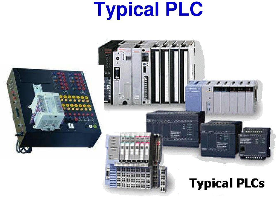
3 Typical PLC
4 Forms of PLCs First developed in 1968, they are now widely used: Two types: 1- Single box type: for small programmable controllers, is supplied as an integral compact package, complete with power supply, processor, memory and input/output units. Typically they may have 6, 8, 12, or 24 inputs and 4, 8, or 16, outputs and a memory store some instructions. Eg. MELSEC FX3U 2- Rack mounted type: for all sizing of programming controllers. It consists of separate modules for power supply, processor, input/output, etc. They are mounted on rails with a metal cabinet. E.g. SIMATIC S7-300/400

5 Input/output processing PLC is continuously running through its program and updating it as a result of the input signals, each such loop is called a cycle. Two methods of processing: 1- Continuous updating 2- Mass updating continuous updating: The cpu scanning the input channels as they occur in the program instructions. Each input is examined individually (delay time 3 ms). The output is latched so that they retain their status until the next update
.")
6 Input/output processing Mass input/ output copying: it works in the following process: 1. Scan all the inputs and copy into RAM 2. Fetch and decode and execute all program instruction in sequence, copying output instruction to RAM 3- Once the program is executed, the CPU performs diagnostics and communication tasks 4- update all outputs Repeat the sequence.

7 Input/Output address The inputs and outputs are identified by their addresses, the notation used depending on the PLC manufacturer. This is the address of the input or output in the memory of the PLC. Its just a number preceded by a letter to indicate whether it is an input or an output With large PLCs having several racks of input and output and a number of modules in each rack, the rack and modules are numbered and so an input or output is identified by its rack number followed by the number of the module in that rack and the number to show its terminal in the module.: The Allen-Bradley PLC-5 has I: 012/03 to indicate an input in rack 01 at module 2 and terminal 03

8 PLC In Control Circuits Architecture External Computer Communication Module PLC Microprocessor Output Module Actuator Process Input Module Sensor

9 Architecture of a PLC It consist essentially of: Central processing unit: control all processes with frequency 1-8 M Hz Memory: Buffers as temporary storage, ROM for system data & RAM for user program Input/output interface: System buses

10 Input/output unit The input/output unit provides the interface between the system and the outside world. The input/ output interface provides isolation and signal conditioning functions so that sensors and actuators can often be directly connected to them without the need for other circuitry. Out devices: motors, starting coils, solenoid valve, etc Input devices: temperature sensors, flow sensors, encoders, etc

11 Input/output unit Electrical isolation from the external world is usually provided by means of opt isolators. Figure shows the basic form of input channel Figure 21.2 Input channel

12 Input/output unit The digital signal that is compatible with the microprocessor of the PLC is 5 volt dc however, signal conditioning in the input channel with isolation enables a wide range of input signals to be supplied. Possible input voltages 5V, 24V, 110V, and 240V. The output to the output unit is digital with a level of 5 V, Three types of outputs are available: Relay type, Transistor type & triac type

13 Input/output unit Three types of outputs are available: Relay type: The signal from the PLC is used to operate a relay and so able to switch currents of a few amperes in an external circuit. The relay isolate the PLC from external world, can be used for AC and DC but they are slow Transistor type: It is used to switch current through external circuit, fast opto-isolators are used to provide isolation, used only for DC switching Triac type: used for both AC and DC Possible output from output channels: 24V,100 ma; 100V dc,1 A; 240V,1A ac; or 240V, 2A ac

14 Inputting Programs Are entered into the input/output from: Small hand- held programming devices, desktop consoles with a visual display or key board and screen

15 Inputting Programs Only when the program has been designed and checked on the programming device is transferred to the memory of the PLC Typical Program memory size is (specified in term of steps) 300 to 1000 step. Program step is an instruction for some event to occur, ex: check status of switch A After developing the program in RAM it may be transferred permanently to the EPROM chip

16 Figure 21.3 (a), (b) Sourcing, (c), (d) sinking
, (d)")
17 Ladder programming The form of programming commonly use with PLC is ladder programming. Each program task is specified as though a rung of a ladder. Thus a rung could specify that the state of switches A and B be examined and if both A and B are closed then a solenoid, the output is energized. Figure 21.4 (a), (b) Alternative ways of drawing an electric circuit, (c) comparable rung in a ladder program

18 Ladder programming The sequence followed by a PLC when carrying out a program: 1- Scan the inputs associated with one rung of the ladder program 2- solve the logic operation involving those inputs Set/ reset the outputs for that rung 3- move on to the next rung and repeat operations 1, 2, 3...and so on until the end of program with each rung of the ladder scanned in turn. The PLC then goes back to the begining of the program and starts again The ladder diagram consists of two vertical lines representing the power rails. Circuits (rung) are connected as horizontal lines,

19 Ladder programming Fig.21.5 shows a basic standared symbols that are used and rung, Inputs must always preceede outputs and there must be at least one output on each line Each rung must start with an input or series of inputs and end with an output

20 Ladder programming Example of a ladder diagram Figure 21.6 Switch controlling a solenoid The output from the PLC is to energise a solenoid when a normally open start switch connnected to the input is activated by being closed This might be a solenoid valve which opens to allow water to enter a vessel.

21 Ladder programming Example of a ladder diagram: An ON/OFF temperature control Figure 21.7 Temperature control system The input goes from low to high when the temparature sensor reaches the set temperature. The output is then to go from ON to OFF.
22 Logic Functions The logic Functions can be obtained by combinations of switches. The Figures shows how ladder programs can be written for such combination Ladder programming AND circuit OR circuit NOR circuit NAND circuit XOR circuit
23 Ladder programming Logic Functions The basic logic functions can be used to obtained more complicated combinations of switches. Consider a situation where a normally open switch A must be activated and either of two other, normally open switches B and C must be activated for a coil to be energised. Figure 21.9 Switches controlling a solenoid
24 Figure Shop door system
25 PLC programming: Instruction List Each horizontal rung on the ladder represents a line in the program and the entire ladder gives the complete program in the ladder language. Using a graphic interface, a programmer can build his program, then translate these symbols into machine language that can be stored in the PLC memory. Alternatively, the ladder program can be translated into an instruction list and entered into the programming panel or computer.
26 PLC programming: Instruction List Instruction lists consist of a series of instruction with each instruction being on a separate line. An instruction consists of an operator followed by one or more operand..e.g. LD A (*load input A*) Comments
27 Instruction List The mnemonics codes used by different PLC manufactures differ but an international standard (IEC ) has been proposed and is widely used Table below shows core mnemonics. For the rest of the following instructions, Mitsubishi mnemonics will be used Table 21.1 Some Instruction code mnemonics
28 Instruction List and Logic Function Figures show how individual rungs on a ladder are entered using the Mitsubishi mnemonics where logic functions are involved Figure (a) AND, (b) OR, (c) NOR, (d) NAND
29 Instruction List and Branching When two parallel arms are involved, Mitsubishi treats the situation by using an ORB instruction to indicate OR together parallel branches as shown in Fig.21.12a. Line 3 describe a new line since it starts with LD/LDI instruction while Siemens use brackets as shown in Fig.21.12b, Figure XOR
30 Latching and internal relays The term latching is used for the circuit that able to hold the output energized even though the input which energizing it ceases. So the output remember its last state. Figure A latch circuit
31 Latching: Examples It is required for the PLC to control a motor so that when the start signal button is momentarily pressed the motor starts and when the stop button is pressed, the motor switches OFF Figure Stop system
32 Internal relays The term internal, auxiliary relay or marker is used for what can be considered as internal relay in PLC. It behaves like relays with their associated contacts, but in reality are not actual relays but simulation by the software of the PLC. Internal can be very useful aids in the implementation of switching sequences. They are often used when there are programs with multiple input conditions.
33 Internal relays: examples They are used when there are programs with multiple input conditions. In Fig a different input arrangement have been implemented by internal Relay Multiple out can also started with internal relays as shown in Fig b (a) An output controlled by two input arrangements, (b) starting of multiple outputs Figure 21.15
34 Internal relays: examples Can be used to reset a latch contact as shown below Figure a latch Resetting
35 Internal relays When the contact of input is closed, the coil battery is energized, this closes the internal relay contacts and so even if contact of the input open as result of power failure, the internal relay contact remain closed. This means that the output controlled by the internal relay remains energized Figure Use of a battery-backed internal relay
36 Data Handling The operations that may be carried out with a PLC on data words include: 1- Moving data 2- Comparison of magnitude of data 3- Arithmetic operations 4- Conversion between number system Data instructions require memory addresses, so data registers are used to stored binary words (8 or 16 bits) and is given an address such as D0, D1, D2 Each instruction has to specify the form of the operation, the source of the data used in terms of its data register and the destination data register of the data
37 Data Handling: Examples Data Movement Data Comparison Temperature alarm example:
38 Data Handling: Examples Arithmetic operation Figure Add data
39 Data Handling: Examples Code Conversion Figure BCD to binary
Programming A PLC. Standard Instructions
 Programming A PLC STEP 7-Micro/WIN32 is the program software used with the S7-2 PLC to create the PLC operating program. STEP 7 consists of a number of instructions that must be arranged in a logical order
Programmable Logic Controller PLC
 Programmable Logic Controller PLC UPCO ICAI Departamento de Electrónica y Automática 1 PLC Definition PLC is a user friendly, microprocessor based, specialized computer that carries out control functions
PROGRAMMABLE LOGIC CONTROLLERS Unit code: A/601/1625 QCF level: 4 Credit value: 15 OUTCOME 3 PART 1
 UNIT 22: PROGRAMMABLE LOGIC CONTROLLERS Unit code: A/601/1625 QCF level: 4 Credit value: 15 OUTCOME 3 PART 1 This work covers part of outcome 3 of the Edexcel standard module: Outcome 3 is the most demanding
3BASIC RELAY INSTRUCTIONS
 M O D U L E T H R E E 3BASIC RELAY INSTRUCTIONS Key Points So far, you have learned about the components of the MicroLogix 1000 PLC, including the CPU, the memory system, the power supply, and the input/output
2011, The McGraw-Hill Companies, Inc. Chapter 5
 Chapter 5 5.1 Processor Memory Organization The memory structure for a PLC processor consists of several areas, some of these having specific roles. With rack-based memory structures addresses are derived
Fig 3. PLC Relay Output
 1. Function of a PLC PLC Basics A PLC is a microprocessor-based controller with multiple inputs and outputs. It uses a programmable memory to store instructions and carry out functions to control machines
Programmable Logic Controllers
 Programmable Logic Controllers PLC Basics Dr. D. J. Jackson Lecture 2-1 Operating systems and application programs A PLC contains a basic operating system that allows for: Downloading and executing user
Ladder and Functional Block Programming
 CHPTER 11 Ladder and Functional lock Programming W. olton This (and the following) chapter comes from the book Programmable Logic Controllers by W. olton, ISN: 9780750681124. The first edition of the book
THE INPUT/OUTPUT SYSTEM. Key Points
 M O D U L E T W O THE 2 INPUT/OUTPUT SYSTEM Key Points In the first module, you learned about the basic architecture and operation of the Allen-Bradley Micrologix 1000, including a brief introduction to
Programmable Logic Controllers Definition. Programmable Logic Controllers History
 Definition A digitally operated electronic apparatus which uses a programmable memory for the internal storage of instructions for implementing specific functions such as logic, sequencing, timing, counting,
Series Six Plus Programmable Controller
 Series Six Plus Programmable Controller Gl?K-0147B June 1989 Central Processor Unit 8-Slot Rack 1l-Slot Rack General Description The Central Processor Unit (CPU) for the Series Six Plus Programmable Logic
PROGRAMMABLE LOGIC CONTROL
 PROGRAMMABLE LOGIC CONTROL James Vernon: control systems principles.co.uk ABSTRACT: This is one of a series of white papers on systems modelling, analysis and control, prepared by Control Systems Principles.co.uk
An overview of Computerised Numeric Control (C.N.C.) and Programmable Logic Control (P.L.C.) in machine automation
 and Programmable Logic Control (P.L.C.) in machine automation") An overview of Computerised Numeric Control (C.N.C.) and Programmable Logic Control (P.L.C.) in machine automation By Pradeep Chatterjee, Engine Division Maintenance, TELCO, Jamshedpur 831010 E-mail: [email protected]
An overview of Computerised Numeric Control (C.N.C.) and Programmable Logic Control (P.L.C.) in machine automation By Pradeep Chatterjee, Engine Division Maintenance, TELCO, Jamshedpur 831010 E-mail: [email protected]
How to read this guide
 How to read this guide The following shows the symbols used in this Quick start guide with descriptions and examples. Symbol Description Example P oint Reference Caution [ ] This symbol explains information
Digital Systems Based on Principles and Applications of Electrical Engineering/Rizzoni (McGraw Hill
 Digital Systems Based on Principles and Applications of Electrical Engineering/Rizzoni (McGraw Hill Objectives: Analyze the operation of sequential logic circuits. Understand the operation of digital counters.
8.1 The Structure and Features of Programmable Logic Controller
 Chapter 8 : Programmable Logic Controller (PLC) 8.1 The Structure and Features of Programmable Logic Controller Programmable logic controllers (PLCs) have been used in industry in one form or another for
MICROPROCESSOR AND MICROCOMPUTER BASICS
 Introduction MICROPROCESSOR AND MICROCOMPUTER BASICS At present there are many types and sizes of computers available. These computers are designed and constructed based on digital and Integrated Circuit
Chapter 2 Logic Gates and Introduction to Computer Architecture
 Chapter 2 Logic Gates and Introduction to Computer Architecture 2.1 Introduction The basic components of an Integrated Circuit (IC) is logic gates which made of transistors, in digital system there are
EXPERIMENT 2 TRAFFIC LIGHT CONTROL SYSTEM FOR AN INTERSECTION USING S7-300 PLC
 YEDITEPE UNIVERSITY ENGINEERING & ARCHITECTURE FACULTY INDUSTRIAL ELECTRONICS LABORATORY EE 432 INDUSTRIAL ELECTRONICS EXPERIMENT 2 TRAFFIC LIGHT CONTROL SYSTEM FOR AN INTERSECTION USING S7-300 PLC Introduction:
Electrical Symbols and Line Diagrams
 Electrical Symbols and Line Diagrams Chapter 3 Material taken from Chapter 3 of One-Line Diagrams One-line diagram a diagram that uses single lines and graphic symbols to indicate the path and components
Programmable Logic Controllers
 Programmable Logic Controllers PLC Addressing and Basic Instructions Dr. D. J. Jackson Lecture 3-1 Basic addressing For the Allen-Bradley PLCs and the simulator used, the input and output image areas (in
PART B QUESTIONS AND ANSWERS UNIT I
 PART B QUESTIONS AND ANSWERS UNIT I 1. Explain the architecture of 8085 microprocessor? Logic pin out of 8085 microprocessor Address bus: unidirectional bus, used as high order bus Data bus: bi-directional
Permissible ambient temperature Operation Storage, transport
 The Sitras PRO combined DC protective unit and controller is used in the power supply for DC railways in mass transit and main-line systems up 3,000 V DC. It protects DC switch gear and contact line systems
40.3. Control Relays and Timers
 .3 Contents EASY500/700/800 Intelligent Relays........ EASY/MFD Expansion Modules............ MFD Intelligent Relays................... EASY/MFD Communication Modules....... EASY/MFD Power Supplies, Accessories
MECE 102 Mechatronics Engineering Orientation
 MECE 102 Mechatronics Engineering Orientation Mechatronic System Components Associate Prof. Dr. of Mechatronics Engineering Çankaya University Compulsory Course in Mechatronics Engineering Credits (2/0/2)
Points Position Indicator (PPI1) for Points Motors with Common Ground
 for Points Motors with Common Ground") Points Position Indicator (PPI1) for Points Motors with Common Ground Monitors Points Action and Operates Leds on a Control Panel Monitors the brief positive operating voltage across points motors when
Points Position Indicator (PPI1) for Points Motors with Common Ground Monitors Points Action and Operates Leds on a Control Panel Monitors the brief positive operating voltage across points motors when
CPU systron S 200 - S 250 - S 250c. systron S 200 - S 250 - S 250c. CPUs to the process modules. Stand-alone PLC
 E031019 000823 systron S 200 - S 250 - S 250c CPU systron S 200 - S 250 - S 250c 45 mm width Flexible and expandable Easy to use software for bus connection (S 250/ S 250c) CPUs to the process modules
General Purpose, Interposing, Solid-State and Specialty Relays. Bulletin 700
 General Purpose, Interposing, Solid-State and Specialty Relays Bulletin 700 Breadth of Product. Ease of Selection. World-class Allen-Bradley relays and timing relays by Rockwell Automation are designed,
PLC SW and Programming. Nagy István, BMF BGK MEI
 PLC SW and Programming Introduction: In the PLCs is usually running 2 Programs: Basic Software: what is the operating system User Program what is the code of instructions written by programators. The PLC
Automation System TROVIS 6400 TROVIS 6493 Compact Controller
 Automation System TROVIS 6400 TROVIS 6493 Compact Controller For panel mounting (front frame 48 x 96 mm/1.89 x 3.78 inch) Application Digital controller to automate industrial and process plants for general
Programmable set for Ethernet Modbus/TCP in IP67 TI-BL67-PG-EN-2
 Type code Ident no. 1545065 Number of channels 2 Dimensions (W x L x H) 108 x 145 x 77.5 mm CoDeSys-programmable acc. to IEC 61131-3 Cable max. 50 m between interface and read/write head 10/100 Mbps Male
PLC Programming for Industrial Automation. Kevin Collins
 PLC Programming for Industrial Automation Kevin Collins Contents Introduction PLC Basics Function of a PLC Inputs and Outputs PLC Architecture and Wiring Diagrams Network Protocols Questions Ladder Programming
Introduction to Electronic Signals
 Introduction to Electronic Signals Oscilloscope An oscilloscope displays voltage changes over time. Use an oscilloscope to view analog and digital signals when required during circuit diagnosis. Fig. 6-01
PROGRAMMABLE LOGIC CONTROLLERS Unit code: A/601/1625 QCF level: 4 Credit value: 15 TUTORIAL OUTCOME 2 Part 1
 UNIT 22: PROGRAMMABLE LOGIC CONTROLLERS Unit code: A/601/1625 QCF level: 4 Credit value: 15 TUTORIAL OUTCOME 2 Part 1 This work covers part of outcome 2 of the Edexcel standard module. The material is
Programmable Logic Controllers Basic Level Textbook TP 301
 Programmable Logic Controllers Basic Level Textbook TP 301 Festo Didactic 093311 en B-II Authorised applications and liability The Learning System for Automation and Technology has been developed and prepared
NTE2053 Integrated Circuit 8 Bit MPU Compatible A/D Converter
 NTE2053 Integrated Circuit 8 Bit MPU Compatible A/D Converter Description: The NTE2053 is a CMOS 8 bit successive approximation Analog to Digital converter in a 20 Lead DIP type package which uses a differential
Solid-State Relays (SSRs) vs Electromechanical Relays (EMRs)
 vs Electromechanical Relays (EMRs)") Oct 2010 Solid-State Relays (SSRs) vs Electromechanical Relays (EMRs) A study on worldwide relays market found the market size of solid state relays to be between $200M and $600M, which represent 17% of
Oct 2010 Solid-State Relays (SSRs) vs Electromechanical Relays (EMRs) A study on worldwide relays market found the market size of solid state relays to be between $200M and $600M, which represent 17% of
Creating Relay Logic Diagrams
 This sample chapter is for review purposes only. Copyright The Goodheart-Willcox Co., Inc. All rights reserved. Creating elay Logic Diagrams Chapter Outline 5. Introduction 5. elay Logic Diagrams 5.3 ules
Inductive Sensors Single or Dual Loop Detectors Type LD with teach-in
 Inductive Sensors Single or Dual Loop Detectors Type LD with teach-in Single or Dual loop detector Automatically adjustment of detection level Manual sensitivity for compensations of variations Easy installation
Designing an efficient Programmable Logic Controller using Programmable System On Chip
 Designing an efficient Programmable Logic Controller using Programmable System On Chip By Raja Narayanasamy, Product Apps Manager Sr, Cypress Semiconductor Corp. A Programmable Logic Controller (PLC) is
1. True or False? A voltage level in the range 0 to 2 volts is interpreted as a binary 1.
 File: chap04, Chapter 04 1. True or False? A voltage level in the range 0 to 2 volts is interpreted as a binary 1. 2. True or False? A gate is a device that accepts a single input signal and produces one
PROGRAMMABLE LOGIC CONTROLLERS Unit code: A/601/1625 QCF level: 4 Credit value: 15
 UNIT 22: PROGRAMMABLE LOGIC CONTROLLERS Unit code: A/601/1625 QCF level: 4 Credit value: 15 ASSIGNMENT 3 DESIGN AND OPERATIONAL CHARACTERISTICS NAME: I agree to the assessment as contained in this assignment.
Programming Timers CHAPTER 4-1 GOALS AND OBJECTIVES 4-2 MECHANICAL TIMING RELAYS
 CHAPTER 4 4-1 GOALS AND OBJECTIVES There are two principal goals of this chapter. The first goal is to provide the student with information on the operation and functions of hardware timers both mechanical
Chapter 5. Components, Symbols, and Circuitry of Air-Conditioning Wiring Diagrams
 Chapter 5 Components, Symbols, and Circuitry of Air-Conditioning Wiring Diagrams Objectives Upon completion of this course, you will be able to: Explain what electrical loads are and their general purpose
DTW Works Master Specification Version 2006
 Issued 2006/08/01 Section 13852 Multiplex Fire Alarm System Page 1 of 10 PART 1 GENERAL 1.1 RELATED WORK.1 Section 01330 Submittal Procedures..2 Section 01780 Closeout Procedures..3 Section 01810 Commissioning..4
Introduction to LogixPro - Lab
 Programmable Logic and Automation Controllers Industrial Control Systems I Introduction to LogixPro - Lab Purpose This is a self-paced lab that will introduce the student to the LogixPro PLC Simulator
Technical Manual. FAN COIL CONTROLLER COOLING or HEATING ANALOG or PWM Art. 119914 631001A
 COOLING or HEATING ANALOG or PWM Art. 119914 631001A TOTAL AUTOMATION GENERAL TRADING CO. LLC SUITE NO.506, LE SOLARIUM OFFICE TOWER, SILICON OASIS, DUBAI. UAE. Tel. +971 4 392 6860, Fax. +971 4 392 6850
POINTS POSITION INDICATOR PPI4
 POINTS POSITION INDICATOR PPI4 Advanced PPI with Adjustable Brightness & Simplified Wiring Monitors the brief positive operating voltage across points motors when they are switched Lights a corresponding
2011, The McGraw-Hill Companies, Inc. Chapter 9
 Chapter 9 9.1 Master Control Reset Instruction Program control instructions are used to enable or disable a block of logic program or to move execution of a program from one place to another place. Program
Advanced Computer Architecture-CS501. Computer Systems Design and Architecture 2.1, 2.2, 3.2
 Lecture Handout Computer Architecture Lecture No. 2 Reading Material Vincent P. Heuring&Harry F. Jordan Chapter 2,Chapter3 Computer Systems Design and Architecture 2.1, 2.2, 3.2 Summary 1) A taxonomy of
Industrial Training Schedule Spring 2012
 Contents About Ashdale Industrial Control Training Courses 3 Mitsubishi GX Developer Software Programming Tool 4 Mitsubishi FX Series PLC Level 1 5 Mitsubishi Variable Speed Inverter Drives 6 Mitsubishi
MICROPROCESSOR. Exclusive for IACE Students www.iace.co.in iacehyd.blogspot.in Ph: 9700077455/422 Page 1
 MICROPROCESSOR A microprocessor incorporates the functions of a computer s central processing unit (CPU) on a single Integrated (IC), or at most a few integrated circuit. It is a multipurpose, programmable
150127-Microprocessor & Assembly Language
 Chapter 3 Z80 Microprocessor Architecture The Z 80 is one of the most talented 8 bit microprocessors, and many microprocessor-based systems are designed around the Z80. The Z80 microprocessor needs an
GENERATOR START CONTROL MODULE - MINI (2 Wire to 3 Wire)
") FEATURES & APPLICATIONS Inexpensive 2 wire to 3 wire start controller for electric start high speed gas generators. Optimized for use with Outback Invertors. Supports three types of 3 wire generator control
FEATURES & APPLICATIONS Inexpensive 2 wire to 3 wire start controller for electric start high speed gas generators. Optimized for use with Outback Invertors. Supports three types of 3 wire generator control
Michelin North America
 www.centecinc.com SC Telephone: 864.527.7750 Outside SC: 800.227.0855 Michelin North America Industrial Maintenance Technical Interview Outline Industrial Maintenance Technical Interview Outline The Technical
Industrial Process Controllers
 Unit 50: Industrial Process Controllers Unit code: QCF Level 3: Credit value: 10 Guided learning hours: 60 Aim and purpose Y/600/0339 BTEC Nationals This unit provides learners with an opportunity to gain
Programmable Controller G Series. New. Models
 Programmable Controller G Series The IMO G6 is a very compact modular programmable controller offering extremely high performance. It is ideal for all applications from process control to machine control
Management Challenge. Managing Hardware Assets. Central Processing Unit. What is a Computer System?
 Management Challenge Managing Hardware Assets What computer processing and storage capability does our organization need to handle its information and business transactions? What arrangement of computers
MODEL 5010 DUAL CHANNEL SMOKE/FIRE DETECTION MODULE
 DESCRIPTION MODEL 5010 DUAL CHANNEL SMOKE/FIRE DETECTION MODULE DESCRIPTION The SST Model 5010 Two Channel Smoke/Fire Detection Module provides two independent detection input channels for the NOVA-5000
A+ Guide to Managing and Maintaining Your PC, 7e. Chapter 1 Introducing Hardware
 A+ Guide to Managing and Maintaining Your PC, 7e Chapter 1 Introducing Hardware Objectives Learn that a computer requires both hardware and software to work Learn about the many different hardware components
1 Application Description... 3. 1.1 Objective... 3 1.2 Goals... 3
 Contents Moxa Technical Support Team [email protected] 1 Application Description... 3 1.1 Objective... 3 1.2 Goals... 3 2 System Topology... 3 3 Hardware and Software Requirements... 4 4 Configuration...
MACHINE ARCHITECTURE & LANGUAGE
 in the name of God the compassionate, the merciful notes on MACHINE ARCHITECTURE & LANGUAGE compiled by Jumong Chap. 9 Microprocessor Fundamentals A system designer should consider a microprocessor-based
Chapter 6. Inside the System Unit. What You Will Learn... Computers Are Your Future. What You Will Learn... Describing Hardware Performance
 What You Will Learn... Computers Are Your Future Chapter 6 Understand how computers represent data Understand the measurements used to describe data transfer rates and data storage capacity List the components
SUBJECT: How to wire a motor starter Number: AN-MC-004 Date Issued: 2/08/2005 Revision: Original
 SUBJECT: How to wire a motor starter Number: AN-MC-004 Date Issued: 2/08/2005 Revision: Original A motor starter is a combination of devices to allow an induction motor to start, run and stop according
Adding Heart to Your Technology
 RMCM-01 Heart Rate Receiver Component Product code #: 39025074 KEY FEATURES High Filtering Unit Designed to work well on constant noise fields SMD component: To be installed as a standard component to
Specifications for EM223 24 VDC 4 In/4 Out and EM223 24 VDC 4 In/4 Relay Out
 SIMATIC S7-200 EM223 Digital Combination Modules EM223 2 VDC In/ Out and EM223 2 VDC In/ Relay Out Table 1 Specifications for EM223 2 VDC In/ Out and EM223 2 VDC In/ Relay Out EM223 2VDC In/Out 6ES7 2231BF200XA0
DRTS 33. The new generation of advanced test equipments for Relays, Energy meters, Transducers and Power quality meters
 The new generation of advanced test equipments for Relays, Energy meters, Transducers and Power quality meters Testing all relay technologies: electromechanical, solid state, numerical and IEC61850 Manual
(Cat. No. 1775-L3) Product Data
 Product Data") (Cat. No. 1775-L3) Product Data When it comes to programmable controllers, the more power you can put into a chassis slot, the more control potential you have. The PLC-3 programmable controller, already
(Cat. No. 1775-L3) Product Data When it comes to programmable controllers, the more power you can put into a chassis slot, the more control potential you have. The PLC-3 programmable controller, already
ABB i-bus KNX Fan Coil Actuator, MDRC FCA/S 1.1M, 2CDG 110 084 R0011
 , 2CDG 110 084 R0011 2CDC 071 112 F0008 The Fan Coil Actuator is a modular installation device (MDRC) in pro M design. It is intended for installation in the distribution board on 35 mm mounting rails.
INDUSTRIAL TF1: 16 keys with LED 6AV1 902-0AA00 KEYBOARDS TF2: 20 keys with LED 6AV1 902-0AB00 6AV3 017-1NE30-0AX0 6AV3 503-1DB10 6AV3 505-1FB12
 Siemens SIMATIC S5 SYSTEMS FOR CONTROL AND MONITORING OPERATOR PANELS INDUSTRIAL TF1: 16 keys with LED 6AV1 902-0AA00 KEYBOARDS TF2: 20 keys with LED 6AV1 902-0AB00 TF3: 24 keys with LED 6AV1 902-0AC00
PLC Based Liquid Filling and Mixing
 PLC Based Liquid Filling and Mixing 1 Mihir Panchal, 2 Aashish Panaskar. 3 Prof. Lalit Kumar KJ College of Engineering and Management Research, Pune, India Abstract: The objective of this paper is to design,
Analog Inputs and Outputs
 Analog Inputs and Outputs PLCs must also work with continuous or analog signals. Typical analog signals are 0-10 VDC or 4-20 ma. Analog signals are used to represent changing values such as speed, temperature,
Figure 1 - Crydom 3RHP Three-phase Hybrid Solid State Contactor. Crydom Inc.
 Crydom RHP Series 3 Phase Hybrid Solid State Contactor By Paul Bachman Fellow Engineer, Crydom, Inc. ABSTRACT Solid State Relays and Contactors (SSRs) have been available in one form or the other for over
Positive-guided relay outputs: 3 safety contacts (N/O), instantaneous. 1 auxiliary contact (N/C), instantaneous
, instantaneous. 1 auxiliary contact (N/C), instantaneous") Safety relay for monitoring E-STOP pushbuttons. Approvals Unit features Positive-guided relay outputs: 3 safety contacts (N/O), instantaneous 1 auxiliary contact (N/C), instantaneous Safe separation of
Safety relay for monitoring E-STOP pushbuttons. Approvals Unit features Positive-guided relay outputs: 3 safety contacts (N/O), instantaneous 1 auxiliary contact (N/C), instantaneous Safe separation of
JNIOR. Overview. Get Connected. Get Results. JNIOR Model 310. JNIOR Model 312. JNIOR Model 314. JNIOR Model 410
 The INTEG is an Ethernet I/O (digital, analog) device that monitors and controls a small set of process signals. functions as both basic I/O for integration with another application or system AND as a
LADDER LOGIC/ FLOWCHART PROGRAMMING DIFFERENCES AND EXAMPLES
 page 1/10 This document is designed as a quick-start primer to assist industrial automation programmers who are familiar with PLCs and Relay Ladder Logic programming to better understand the corresponding
Siemens AG 2011 SINAMICS V60. The perfect solution for basic servo applications. Brochure May 2011 SINAMICS. Answers for industry.
 The perfect solution for basic servo applications Brochure May 2011 SINAMICS Answers for industry. with 1FL5 servomotors The solution for basic servo applications There is a requirement to automate motion
Logical Operations. Control Unit. Contents. Arithmetic Operations. Objectives. The Central Processing Unit: Arithmetic / Logic Unit.
 Objectives The Central Processing Unit: What Goes on Inside the Computer Chapter 4 Identify the components of the central processing unit and how they work together and interact with memory Describe how
SIMATIC NET. CP 243-2 AS-Interface Master B C. Preface Contents. Technical Description and Installation Instructions Interface to the User Program
 Preface Contents SIMATIC NET CP 243-2 AS-Interface Master Manual Technical Description and Installation Instructions Interface to the User Program 2 in the S7-200 CPU Access to the Data of the AS-i Slaves
Single Channel Loop Detector
 Single Channel Loop Detector Model - LD100 Series The LD100 is a single channel inductive loop detector designed for parking and access control applications. The detector is connected to an inductive loop
Disturbance Recoder SPCR 8C27. Product Guide
 Issued: April 1999 Status: Updated Version: C/26.04.2006 Data subject to change without notice Features Versatile digital disturbance recorder module for recording various phenomena in the electric power
COMBINATIONAL and SEQUENTIAL LOGIC CIRCUITS Hardware implementation and software design
 PH-315 COMINATIONAL and SEUENTIAL LOGIC CIRCUITS Hardware implementation and software design A La Rosa I PURPOSE: To familiarize with combinational and sequential logic circuits Combinational circuits
Process modules Digital input PMI for 24 V DC inputs for 120 V AC inputs
 E031026 000823 Process modules Digital input PMI for inputs for 120 V AC inputs PMI Input E4, E5, GND L- PMI 120 V AC Input E4, E5, Common C E6, E7, GND L- E6, E7, Common C LEDs for the inputs operation
mecotron Safety relay ESTOP-2 For emergency stop monitoring
 E0006 000824 Safety relay E-2 For emergency stop monitoring Description The safety module E-2 for emergency stop monitoring is used for safety breaking one or more circuits and is designed to be incorporated
Safety Relays ESM/ESM-F
 Safety Relays ESM/ESM-F More than safety. Safety More than safety. Emil Euchner, the company s founder and inventor of the multiple limit switch, circa 1928. Around the world the Swabian specialists in
456 26 Microcontrollers Figure 26-1 Objectives Key Words and Terms 26.1 OVERVIEW OF THE MICROCONTROLLER microcontroller
 This sample chapter is for review purposes only. Copyright The Goodheart-Willcox Co., Inc. All rights reserved. 456 Electronic Communication and Data Systems Objectives After studying this chapter, you
CSCI 4717 Computer Architecture. Function. Data Storage. Data Processing. Data movement to a peripheral. Data Movement
 CSCI 4717/5717 Computer Architecture Topic: Functional View & History Reading: Sections 1.2, 2.1, & 2.3 Function All computer functions are comprised of four basic operations: Data processing Data storage
MIDECO 64-outputs MIDI note decoder USER MANUAL. Roman Sowa 2012
 MIDECO 64-outputs MIDI note decoder USER MANUAL Roman Sowa 2012 www.midi-hardware.com 1.Overview Thank you for choosing MIDECO as your new MIDI-to-digital converter. This short manual will guide you through
Safety technique. Emergency stop module BO 5988 safemaster
 Safety technique Emergency stop module BO 5988 safemaster 0221562 Function diagram Pushbutton on Mains or emergencystop () K1 According to EC Directive for machines 98/37/EG According to IEC/E 60204-1
101 BASICS SERIES LEARNING MODULE 24: PROGRAMMABLE LOGIC CONTROLLERS (PLCS) Cutler-Hammer
 Cutler-Hammer") 101 BASICS SERIES LEARNING MODULE 24: PROGRAMMABLE LOGIC CONTROLLERS (PLCS) Cutler-Hammer WELCOME Welcome to Module 24, which covers Programmable Logic Controllers, or PLCs. The Programmable Logic Controller
101 BASICS SERIES LEARNING MODULE 24: PROGRAMMABLE LOGIC CONTROLLERS (PLCS) Cutler-Hammer WELCOME Welcome to Module 24, which covers Programmable Logic Controllers, or PLCs. The Programmable Logic Controller
VIBRATION MONITORING OF FANS INSTALLED IN ROAD TUNNELS
 VIBRATION MONITORING OF FANS INSTALLED IN ROAD TUNNELS CEMB SPA Via Risorgimento, 9 Mandello del Lario (Lc), Italy [email protected] www.cemb.com INSTRUMENT FOR MONITORING VIBRATIONS OF FANS INSTALLED IN ROAD
LEVERAGING FPGA AND CPLD DIGITAL LOGIC TO IMPLEMENT ANALOG TO DIGITAL CONVERTERS
 LEVERAGING FPGA AND CPLD DIGITAL LOGIC TO IMPLEMENT ANALOG TO DIGITAL CONVERTERS March 2010 Lattice Semiconductor 5555 Northeast Moore Ct. Hillsboro, Oregon 97124 USA Telephone: (503) 268-8000 www.latticesemi.com
(Refer Slide Time: 00:01:16 min)
") Digital Computer Organization Prof. P. K. Biswas Department of Electronic & Electrical Communication Engineering Indian Institute of Technology, Kharagpur Lecture No. # 04 CPU Design: Tirning & Control
Digital Computer Organization Prof. P. K. Biswas Department of Electronic & Electrical Communication Engineering Indian Institute of Technology, Kharagpur Lecture No. # 04 CPU Design: Tirning & Control
Reyrolle Protection Devices. 7PG17 - XR Intertripping, Interposing, Supervision and Special Purpose Relays. Answers for energy
 Reyrolle Protection Devices 7PG17 - XR Intertripping, Interposing, Supervision and Special Purpose Relays. Answers for energy Siemens Protection Devices Limited 2 7PG17 XR101 & XR102 Intertripping Relay
Module 2. Embedded Processors and Memory. Version 2 EE IIT, Kharagpur 1
 Module 2 Embedded Processors and Memory Version 2 EE IIT, Kharagpur 1 Lesson 5 Memory-I Version 2 EE IIT, Kharagpur 2 Instructional Objectives After going through this lesson the student would Pre-Requisite
Analog Input Module Cat. No. 1771 IFE User Manual
 User Manual Because of the variety of uses for the products described in this publication, those responsible for the application and use of this control equipment must satisfy themselves that all necessary
TLK 48 MICROPROCESSOR-BASED DIGITAL ELECTRONIC REGULATOR
 TLK 48 MICROPROCESSOR-BASED DIGITAL ELECTRONIC REGULATOR TECHNICAL DATA CARATTERISTICHE MECCANICHE Housing Self-extinguishing plastic, UL 94 V0 Dimensions 48x48 mm DIN depth 98 mm Weight 225 g approx.
RDJ10RF/SET. Wireless room temperature controller with 24-hour time switch and LCD. Programmable, for heating systems
 3 072 RDJ10RF RCR10/433 Wireless room temperature controller with 24-hour time switch and LCD Programmable, for heating systems RDJ10RF/SET Operating modes: Automatic, Comfort, Energy Saving, and Frost
Technical Training Module ( 30 Days)
") Annexure - I Technical Training Module ( 30 Days) Section 1 : Programmable Logic Controller (PLC) 1. Introduction to Programmable Logic Controller - A Brief History, Need and advantages of PLC, PLC configuration,
Annexure - I Technical Training Module ( 30 Days) Section 1 : Programmable Logic Controller (PLC) 1. Introduction to Programmable Logic Controller - A Brief History, Need and advantages of PLC, PLC configuration,
Industrial Automation Training Academy. PLC, HMI & Drives Training Programs Duration: 6 Months (180 ~ 240 Hours)
") nfi Industrial Automation Training Academy Presents PLC, HMI & Drives Training Programs Duration: 6 Months (180 ~ 240 Hours) For: Electronics & Communication Engineering Electrical Engineering Instrumentation
nfi Industrial Automation Training Academy Presents PLC, HMI & Drives Training Programs Duration: 6 Months (180 ~ 240 Hours) For: Electronics & Communication Engineering Electrical Engineering Instrumentation