Digital Fundamentals
|
|
|
- Brendan Shaw
- 8 years ago
- Views:
Transcription
1 igital Fundamentals with PL Programming Floyd Chapter 9 Floyd, igital Fundamentals, 10 th ed, Upper Saddle River, NJ All Rights Reserved Summary Latches (biestables) A latch is a temporary storage device that has two stable states (bistable). It is a basic form of memory. The S-R (Set-Reset) latch is the most basic type. It can be constructed from NOR gates or NAN gates. With NOR gates, the latch responds to active-high inputs; with NAN gates, it responds to active-low inputs. S R Floyd, igital Fundamentals, 10 th ed, Upper Saddle River, NJ All Rights Reserved

2 Funcionamiento S-R Summary The active-high S-R latch is in a stable (latched) condition when both inputs are LOW. Assume the latch is initially RESET ( = 0) and the inputs are at their inactive level (0). To SET the latch ( = 1), a momentary HIGH signal is applied to the S input while the R remains LOW. To RESET the latch ( = 0), a momentary HIGH signal is applied to the R input while the S remains LOW. 0 R 10 Latch initially RESET 01 0 S 0 0 R S Latch initially SET Floyd, igital Fundamentals, 10 th ed, Upper Saddle River, NJ All Rights Reserved Funcionamiento S -R Summary The active-low S-R latch is in a stable (latched) condition when both inputs are HIGH. Assume the latch is initially RESET ( = 0) and the inputs are at their inactive level (1). To SET the latch ( = 1), a momentary LOW signal is applied to the S input while the R remains HIGH. To RESET the latch a momentary LOW is applied to the R input while S is HIGH. Never apply an active set and reset at the same time (invalid). 1 S 10 Latch initially RESET 01 1 R 1 S 1 R 01 Latch initially 10 SET Floyd, igital Fundamentals, 10 th ed, Upper Saddle River, NJ All Rights Reserved

3 Símbolos lógicos Tabla de verdad del S -R Funcionamiento de un S -R

4 Otra forma de expresar la tabla de verdad del S -R Tabla de verdad del S-R

5 Latch S-R con puerta (entrada de habilitación) Tabla de verdad
")
6 Latch Memoriza el bit en la entrada : será igual a cuando la entrada EN está activa. Floyd, igital Fundamentals, 10 th ed, Upper Saddle River, NJ All Rights Reserved Otra forma de expresar la tabla de verdad Funcionamiento en el tiempo

7 Flip-flops Summary A flip-flop differs from a latch in the manner it changes states. A flip-flop is a clocked (sincronizado) device, in which only the clock edge determines when a new bit is entered. The active edge can be positive or negative. C C ynamic input indicator (a) Positive edge-triggered (b) Negative edge-triggered Floyd, igital Fundamentals, 10 th ed, Upper Saddle River, NJ All Rights Reserved Flip flops sincronizados por flanco de subida y de bajada
 Positive edge-triggered (b) Negative edge-triggered Floyd, igital Fundamentals, 10 th")
8 Funcionamiento de un flip-flop S-R sincronizado por flanco de subida

9 Un flip-flop sincronizado por flanco de subida Flip-flops Summary The J-K flip-flop is more versatile than the flip flop. In addition to the clock input, it has two inputs, labeled J and K. When both J and K = 1, the output changes states (toggles) on the active clock edge (in this case, the rising edge). J Inputs K Outputs Comments No change RESET SET 1 1 Toggle 0 0 Floyd, igital Fundamentals, 10 th ed, Upper Saddle River, NJ All Rights Reserved

10 Funcionamiento J K Notice that the outputs change on the leading edge of the clock. Set Toggle Set Latch J K Floyd, igital Fundamentals, 10 th ed, Upper Saddle River, NJ All Rights Reserved Funcionamiento del flip-flop J-K sincronizado por flanco de bajada

11 Summary Entradas asíncronas Synchronous inputs are transferred in the triggering edge of the clock (for example the or J-K inputs). Most flipflops have other inputs that are asynchronous, meaning they affect the output independent of the clock. Two such inputs are normally labeled preset (PRE) and clear (CLR). These inputs are usually active LOW. A J-K flip flop with active LOW preset and CLR is shown. PRE J K CLR Floyd, igital Fundamentals, 10 th ed, Upper Saddle River, NJ All Rights Reserved PRE Funcionamiento J K J CLR Set Toggle Set Reset Toggle Latch K PRE CLR Set Reset Floyd, igital Fundamentals, 10 th ed, Upper Saddle River, NJ All Rights Reserved

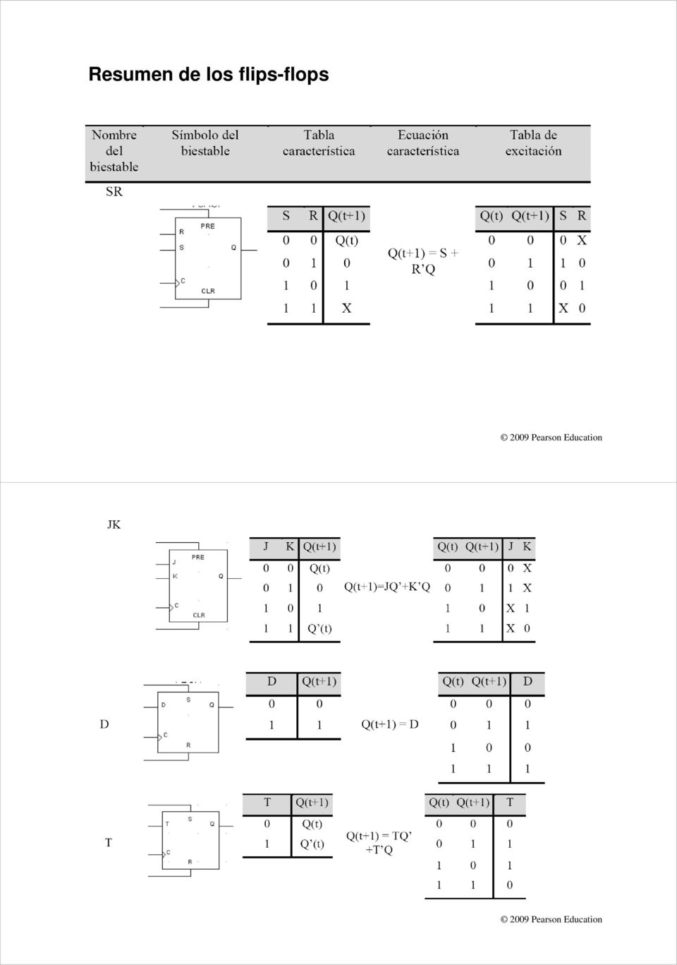
12 Resumen de los flips-flops
13 Flip-flop Characteristics Summary The propagation delay time is the time required for an input to cause a change in the output. It is measured from the 50% levels. Figure Propagation delays, clock to output. Floyd, igital Fundamentals, 10 th ed, Upper Saddle River, NJ All Rights Reserved Retrasos de propagación de las entradas asíncronas Figure Propagation delays, preset input to output and clear input to output.

14 Flip-flop Characteristics Summary Set-up time and hold time are times required before and after the clock transition that data must be present to be reliably clocked into the flip-flop. Setup time is the minimum time for the data to be present before the clock. Set-up time, t s Hold time is the minimum time for the data to remain after the clock. Hold time, t H Floyd, igital Fundamentals, 10 th ed, Upper Saddle River, NJ All Rights Reserved Set-up time Figure Set-up time (t s ). The logic level must be present on the input for a time equal to or greater than t s before the triggering edge of the clock pulse for reliable data entry.
.")
15 Hold time Figure Hold time (t h ). The logic level must remain on the input for a time equal to or greater than t h after the triggering edge of the clock pulse for reliable data entry.

16 Summary Flip-flop Applications Principal flip-flop applications are for temporary data storage, as frequency dividers, and in counters (which are covered in detail in Chapter 10). C C R Output lines 0 1 R Typically, for data storage applications, a group of flip-flops are connected to parallel data lines and clocked together. ata is stored until the next clock pulse. Parallel data input lines Clock C R C 2 3 Clear R Floyd, igital Fundamentals, 10 th ed, Upper Saddle River, NJ All Rights Reserved Figure Example of flip-flops used in a basic register for parallel data storage.

17 Flip-flop Applications Summary For frequency division, it is simple to use a flip-flop in the toggle mode or to chain a series of toggle flip flops to continue to divide by two. One flip-flop will divide f in by 2, two flip-flops will divide f in by 4 (and so on). A side benefit of frequency division is that the output has an exact 50% duty cycle. Floyd, igital Fundamentals, 10 th ed, Upper Saddle River, NJ All Rights Reserved Figure The J-K flip-flop as a divide-by-2 device. is one-half the frequency of.

18 Figure Example of two J-K flip-flops used to divide the clock frequency by 4. A is one-half and B is one-fourth the frequency of.

19 Aplicación: generar una cuenta Figure Flip-flops used to generate a binary count sequence. Two repetitions (00, 01, 10, 11) are shown. Ejemplo: determinar la cuenta generada
 are shown.")
20 Selected Key Terms Latch Bistable Clock flip-flop J-K flip-flop A bistable digital circuit used for storing a bit. Having two stable states. Latches and flip-flops are bistable multivibrators. A triggering input of a flip-flop. A type of bistable multivibrator in which the output assumes the state of the input on the triggering edge of a clock pulse. A type of flip-flop that can operate in the SET, RESET, no-change, and toggle modes. Selected Key Terms Propagation delay time Set-up time Hold time Timer Registered The interval of time required after an input signal has been applied for the resulting output signal to change. The time interval required for the input levels to be on a digital circuit. The time interval required for the input levels to remain steady to a flip-flop after the triggering edge in order to reliably activate the device. A circuit that can be used as a one-shot or as an oscillator. A CPL macrocell output configuration where the output comes from a flip-flop.

21 1. The output of a latch will not change if a. the output is LOW b. Enable is not active c. is LOW d. all of the above Pearson Pearson Education Education 2. The flip-flop shown will a. set on the next clock pulse b. reset on the next clock pulse c. latch on the next clock pulse d. toggle on the next clock pulse
22 3. For the J-K flip-flop shown, the number of inputs that are asynchronous is a. 1 b. 2 c. 3 d. 4 J K PRE CLR Pearson Pearson Education Education 4. Assume the output is initially HIGH on a leading edge triggered J-K flip flop. For the inputs shown, the output will go from HIGH to LOW on which clock pulse? a. 1 b. 2 c. 3 d. 4 J K
23 5. The time interval illustrated is called a. t PHL 50% point on triggering edge b. t PLH c. set-up time d. hold time? 50% point on LOW-to- HIGH transition of Pearson Pearson Education Education 6. The time interval illustrated is called a. t PHL b. t PLH c. set-up time d. hold time?
24 7. The application illustrated is a a. astable multivibrator HIGH HIGH b. data storage device c. frequency multiplier d. frequency divider f in J A K J B K f out Pearson Pearson Education Education 8. The application illustrated is a a. astable multivibrator b. data storage device c. frequency multiplier d. frequency divider Parallel data input lines C C C R R R Output lines Clock C 3 Clear R
25 9. A retriggerable one-shot with an active HIGH output has a pulse width of 20 ms and is triggered from a 60 Hz line. The output will be a a. series of 16.7 ms pulses b. series of 20 ms pulses c. constant LOW d. constant HIGH Pearson Pearson Education Education Answers: 1. b 6. d 2. d 7. d 3. b 8. b 4. c 9. d 5. b 10. a
Chapter 9 Latches, Flip-Flops, and Timers
 ETEC 23 Programmable Logic Devices Chapter 9 Latches, Flip-Flops, and Timers Shawnee State University Department of Industrial and Engineering Technologies Copyright 27 by Janna B. Gallaher Latches A temporary
Memory Elements. Combinational logic cannot remember
 Memory Elements Combinational logic cannot remember Output logic values are function of inputs only Feedback is needed to be able to remember a logic value Memory elements are needed in most digital logic
Lesson 12 Sequential Circuits: Flip-Flops
 Lesson 12 Sequential Circuits: Flip-Flops 1. Overview of a Synchronous Sequential Circuit We saw from last lesson that the level sensitive latches could cause instability in a sequential system. This instability
ECE380 Digital Logic
 ECE38 igital Logic Flip-Flops, Registers and Counters: Flip-Flops r.. J. Jackson Lecture 25- Flip-flops The gated latch circuits presented are level sensitive and can change states more than once during
CHAPTER 11 LATCHES AND FLIP-FLOPS
 CHAPTER 11 LATCHES AND FLIP-FLOPS This chapter in the book includes: Objectives Study Guide 11.1 Introduction 11.2 Set-Reset Latch 11.3 Gated D Latch 11.4 Edge-Triggered D Flip-Flop 11.5 S-R Flip-Flop
Counters. Present State Next State A B A B 0 0 0 1 0 1 1 0 1 0 1 1 1 1 0 0
 ounter ounters ounters are a specific type of sequential circuit. Like registers, the state, or the flip-flop values themselves, serves as the output. The output value increases by one on each clock cycle.
Engr354: Digital Logic Circuits
 Engr354: igital Circuits Chapter 7 Sequential Elements r. Curtis Nelson Sequential Elements In this chapter you will learn about: circuits that can store information; Basic cells, latches, and flip-flops;
Module 3: Floyd, Digital Fundamental
 Module 3: Lecturer : Yongsheng Gao Room : Tech - 3.25 Email : yongsheng.gao@griffith.edu.au Structure : 6 lectures 1 Tutorial Assessment: 1 Laboratory (5%) 1 Test (20%) Textbook : Floyd, Digital Fundamental
Experiment # 9. Clock generator circuits & Counters. Eng. Waleed Y. Mousa
 Experiment # 9 Clock generator circuits & Counters Eng. Waleed Y. Mousa 1. Objectives: 1. Understanding the principles and construction of Clock generator. 2. To be familiar with clock pulse generation
Having read this workbook you should be able to: recognise the arrangement of NAND gates used to form an S-R flip-flop.
 Objectives Having read this workbook you should be able to: recognise the arrangement of NAND gates used to form an S-R flip-flop. describe how such a flip-flop can be SET and RESET. describe the disadvantage
Fig1-1 2-bit asynchronous counter
 Digital electronics 1-Sequential circuit counters Such a group of flip- flops is a counter. The number of flip-flops used and the way in which they are connected determine the number of states and also
Latches, the D Flip-Flop & Counter Design. ECE 152A Winter 2012
 Latches, the D Flip-Flop & Counter Design ECE 52A Winter 22 Reading Assignment Brown and Vranesic 7 Flip-Flops, Registers, Counters and a Simple Processor 7. Basic Latch 7.2 Gated SR Latch 7.2. Gated SR
Asynchronous Counters. Asynchronous Counters
 Counters and State Machine Design November 25 Asynchronous Counters ENGI 25 ELEC 24 Asynchronous Counters The term Asynchronous refers to events that do not occur at the same time With respect to counter
Master/Slave Flip Flops
 Master/Slave Flip Flops Page 1 A Master/Slave Flip Flop ( Type) Gated latch(master) Gated latch (slave) 1 Gate Gate GATE Either: The master is loading (the master in on) or The slave is loading (the slave
Sequential Logic Design Principles.Latches and Flip-Flops
 Sequential Logic Design Principles.Latches and Flip-Flops Doru Todinca Department of Computers Politehnica University of Timisoara Outline Introduction Bistable Elements Latches and Flip-Flops S-R Latch
ETEC 2301 Programmable Logic Devices. Chapter 10 Counters. Shawnee State University Department of Industrial and Engineering Technologies
 ETEC 2301 Programmable Logic Devices Chapter 10 Counters Shawnee State University Department of Industrial and Engineering Technologies Copyright 2007 by Janna B. Gallaher Asynchronous Counter Operation
Flip-Flops, Registers, Counters, and a Simple Processor
 June 8, 22 5:56 vra235_ch7 Sheet number Page number 349 black chapter 7 Flip-Flops, Registers, Counters, and a Simple Processor 7. Ng f3, h7 h6 349 June 8, 22 5:56 vra235_ch7 Sheet number 2 Page number
BINARY CODED DECIMAL: B.C.D.
 BINARY CODED DECIMAL: B.C.D. ANOTHER METHOD TO REPRESENT DECIMAL NUMBERS USEFUL BECAUSE MANY DIGITAL DEVICES PROCESS + DISPLAY NUMBERS IN TENS IN BCD EACH NUMBER IS DEFINED BY A BINARY CODE OF 4 BITS.
Lecture-3 MEMORY: Development of Memory:
 Lecture-3 MEMORY: It is a storage device. It stores program data and the results. There are two kind of memories; semiconductor memories & magnetic memories. Semiconductor memories are faster, smaller,
Flip-Flops and Sequential Circuit Design. ECE 152A Winter 2012
 Flip-Flops and Sequential Circuit Design ECE 52 Winter 22 Reading ssignment Brown and Vranesic 7 Flip-Flops, Registers, Counters and a Simple Processor 7.5 T Flip-Flop 7.5. Configurable Flip-Flops 7.6
Flip-Flops and Sequential Circuit Design
 Flip-Flops and Sequential Circuit Design ECE 52 Winter 22 Reading ssignment Brown and Vranesic 7 Flip-Flops, Registers, Counters and a Simple Processor 7.5 T Flip-Flop 7.5. Configurable Flip-Flops 7.6
WEEK 8.1 Registers and Counters. ECE124 Digital Circuits and Systems Page 1
 WEEK 8.1 egisters and Counters ECE124 igital Circuits and Systems Page 1 Additional schematic FF symbols Active low set and reset signals. S Active high set and reset signals. S ECE124 igital Circuits
Chapter 8. Sequential Circuits for Registers and Counters
 Chapter 8 Sequential Circuits for Registers and Counters Lesson 3 COUNTERS Ch16L3- "Digital Principles and Design", Raj Kamal, Pearson Education, 2006 2 Outline Counters T-FF Basic Counting element State
L4: Sequential Building Blocks (Flip-flops, Latches and Registers)
") L4: Sequential Building Blocks (Flip-flops, Latches and Registers) Acknowledgements: Materials in this lecture are courtesy of the following sources and are used with permission. Prof. Randy Katz (Unified
L4: Sequential Building Blocks (Flip-flops, Latches and Registers) Acknowledgements: Materials in this lecture are courtesy of the following sources and are used with permission. Prof. Randy Katz (Unified
EE 42/100 Lecture 24: Latches and Flip Flops. Rev B 4/21/2010 (2:04 PM) Prof. Ali M. Niknejad
 Prof. Ali M. Niknejad") A. M. Niknejad University of California, Berkeley EE 100 / 42 Lecture 24 p. 1/20 EE 42/100 Lecture 24: Latches and Flip Flops ELECTRONICS Rev B 4/21/2010 (2:04 PM) Prof. Ali M. Niknejad University of California,
A. M. Niknejad University of California, Berkeley EE 100 / 42 Lecture 24 p. 1/20 EE 42/100 Lecture 24: Latches and Flip Flops ELECTRONICS Rev B 4/21/2010 (2:04 PM) Prof. Ali M. Niknejad University of California,
SEQUENTIAL CIRCUITS. Block diagram. Flip Flop. S-R Flip Flop. Block Diagram. Circuit Diagram
 SEQUENTIAL CIRCUITS http://www.tutorialspoint.com/computer_logical_organization/sequential_circuits.htm Copyright tutorialspoint.com The combinational circuit does not use any memory. Hence the previous
To design digital counter circuits using JK-Flip-Flop. To implement counter using 74LS193 IC.
 8.1 Objectives To design digital counter circuits using JK-Flip-Flop. To implement counter using 74LS193 IC. 8.2 Introduction Circuits for counting events are frequently used in computers and other digital
Sequential Logic: Clocks, Registers, etc.
 ENEE 245: igital Circuits & Systems Lab Lab 2 : Clocks, Registers, etc. ENEE 245: igital Circuits and Systems Laboratory Lab 2 Objectives The objectives of this laboratory are the following: To design
Wiki Lab Book. This week is practice for wiki usage during the project.
 Wiki Lab Book Use a wiki as a lab book. Wikis are excellent tools for collaborative work (i.e. where you need to efficiently share lots of information and files with multiple people). This week is practice
A Lesson on Digital Clocks, One Shots and Counters
 A Lesson on Digital Clocks, One Shots and Counters Topics Clocks & Oscillators LM 555 Timer IC Crystal Oscillators Selection of Variable Resistors Schmitt Gates Power-On Reset Circuits One Shots Counters
Digital Systems Based on Principles and Applications of Electrical Engineering/Rizzoni (McGraw Hill
 Digital Systems Based on Principles and Applications of Electrical Engineering/Rizzoni (McGraw Hill Objectives: Analyze the operation of sequential logic circuits. Understand the operation of digital counters.
Contents COUNTER. Unit III- Counters
 COUNTER Contents COUNTER...1 Frequency Division...2 Divide-by-2 Counter... 3 Toggle Flip-Flop...3 Frequency Division using Toggle Flip-flops...5 Truth Table for a 3-bit Asynchronous Up Counter...6 Modulo
Lecture 8: Synchronous Digital Systems
 Lecture 8: Synchronous Digital Systems The distinguishing feature of a synchronous digital system is that the circuit only changes in response to a system clock. For example, consider the edge triggered
Digital Logic Design Sequential circuits
 Digital Logic Design Sequential circuits Dr. Eng. Ahmed H. Madian E-mail: ahmed.madian@guc.edu.eg Dr. Eng. Rania.Swief E-mail: rania.swief@guc.edu.eg Dr. Eng. Ahmed H. Madian Registers An n-bit register
DIGITAL COUNTERS. Q B Q A = 00 initially. Q B Q A = 01 after the first clock pulse.
 DIGITAL COUNTERS http://www.tutorialspoint.com/computer_logical_organization/digital_counters.htm Copyright tutorialspoint.com Counter is a sequential circuit. A digital circuit which is used for a counting
CDA 3200 Digital Systems. Instructor: Dr. Janusz Zalewski Developed by: Dr. Dahai Guo Spring 2012
 CDA 3200 Digital Systems Instructor: Dr. Janusz Zalewski Developed by: Dr. Dahai Guo Spring 2012 Outline SR Latch D Latch Edge-Triggered D Flip-Flop (FF) S-R Flip-Flop (FF) J-K Flip-Flop (FF) T Flip-Flop
Theory of Logic Circuits. Laboratory manual. Exercise 3
 Zakład Mikroinformatyki i Teorii Automatów yfrowych Theory of Logic ircuits Laboratory manual Exercise 3 Bistable devices 2008 Krzysztof yran, Piotr zekalski (edt.) 1. lassification of bistable devices
DIGITAL TECHNICS II. Dr. Bálint Pődör. Óbuda University, Microelectronics and Technology Institute
 DIGITAL TECHNICS II Dr. Bálint Pődör Óbuda University, Microelectronics and Technology Institute 2. LECTURE: ELEMENTARY SEUENTIAL CIRCUITS: FLIP-FLOPS 1st year BSc course 2nd (Spring) term 2012/2013 1
DM74LS169A Synchronous 4-Bit Up/Down Binary Counter
 Synchronous 4-Bit Up/Down Binary Counter General Description This synchronous presettable counter features an internal carry look-ahead for cascading in high-speed counting applications. Synchronous operation
Counters and Decoders
 Physics 3330 Experiment #10 Fall 1999 Purpose Counters and Decoders In this experiment, you will design and construct a 4-bit ripple-through decade counter with a decimal read-out display. Such a counter
Sequential Logic. (Materials taken from: Principles of Computer Hardware by Alan Clements )
") Sequential Logic (Materials taken from: Principles of Computer Hardware by Alan Clements ) Sequential vs. Combinational Circuits Combinatorial circuits: their outputs are computed entirely from their present
Sequential Logic (Materials taken from: Principles of Computer Hardware by Alan Clements ) Sequential vs. Combinational Circuits Combinatorial circuits: their outputs are computed entirely from their present
Design Example: Counters. Design Example: Counters. 3-Bit Binary Counter. 3-Bit Binary Counter. Other useful counters:
 Design Eample: ers er: a sequential circuit that repeats a specified sequence of output upon clock pulses. A,B,C,, Z. G, O, T, E, R, P, S,!.,,,,,,,7. 7,,,,,,,.,,,,,,,,,,,. Binary counter: follows the binary
DATA SHEET. HEF40193B MSI 4-bit up/down binary counter. For a complete data sheet, please also download: INTEGRATED CIRCUITS
 INTEGRATED CIRCUITS DATA SHEET For a complete data sheet, please also download: The IC04 LOCMOS HE4000B Logic Family Specifications HEF, HEC The IC04 LOCMOS HE4000B Logic Package Outlines/Information HEF,
So far we have investigated combinational logic for which the output of the logic devices/circuits depends only on the present state of the inputs.
 equential Logic o far we have investigated combinational logic for which the output of the logic devices/circuits depends only on the present state of the inputs. In sequential logic the output of the
DATA SHEETS DE COMPONENTES DA FAMÍLIA LÓGICA TTL GATES AND INVERTERS POSITIVES NAND GATES AND INVERTERS DESCRIÇÃO
 GATES AND INVERTERS POSITIVES NAND GATES AND INVERTERS Hex Invertes 74LS04 Quadruple 2 Inputs Gates 74LS00 Triple 3 Inputs Gates 74LS10 Dual 4 Inputs Gates 74LS20 8 Inputs Gates 74LS30 13 Inputs Gates
Combinational Logic Design Process
 Combinational Logic Design Process Create truth table from specification Generate K-maps & obtain logic equations Draw logic diagram (sharing common gates) Simulate circuit for design verification Debug
74LS193 Synchronous 4-Bit Binary Counter with Dual Clock
 74LS193 Synchronous 4-Bit Binary Counter with Dual Clock General Description The DM74LS193 circuit is a synchronous up/down 4-bit binary counter. Synchronous operation is provided by having all flip-flops
DIGITAL ELECTRONICS. Counters. By: Electrical Engineering Department
 Counters By: Electrical Engineering Department 1 Counters Upon completion of the chapter, students should be able to:.1 Understand the basic concepts of asynchronous counter and synchronous counters, and
DM9368 7-Segment Decoder/Driver/Latch with Constant Current Source Outputs
 DM9368 7-Segment Decoder/Driver/Latch with Constant Current Source Outputs General Description The DM9368 is a 7-segment decoder driver incorporating input latches and constant current output circuits
A Lesson on Digital Clocks, One Shots and Counters
 A Lesson on Digital Clocks, One Shots and Counters Topics Clocks & Oscillators LM 555 Timer IC Crystal Oscillators Selection of Variable Resistors Schmitt Gates Power-On Reset Circuits One Shots Counters
Timing Methodologies (cont d) Registers. Typical timing specifications. Synchronous System Model. Short Paths. System Clock Frequency
 Registers. Typical timing specifications. Synchronous System Model. Short Paths. System Clock Frequency") Registers Timing Methodologies (cont d) Sample data using clock Hold data between clock cycles Computation (and delay) occurs between registers efinition of terms setup time: minimum time before the clocking
Registers Timing Methodologies (cont d) Sample data using clock Hold data between clock cycles Computation (and delay) occurs between registers efinition of terms setup time: minimum time before the clocking
Chapter 5. Sequential Logic
 Chapter 5 Sequential Logic Sequential Circuits (/2) Combinational circuits: a. contain no memory elements b. the outputs depends on the current inputs Sequential circuits: a feedback path outputs depends
Cascaded Counters. Page 1 BYU
 Cascaded Counters Page 1 Mod-N Counters Generally we are interested in counters that count up to specific count values Not just powers of 2 A mod-n counter has N states Counts from 0 to N-1 then rolls
2 : BISTABLES. In this Chapter, you will find out about bistables which are the fundamental building blocks of electronic counting circuits.
 2 : BITABLE In this Chapter, you will find out about bistables which are the fundamental building blos of electronic counting circuits. et-reset bistable A bistable circuit, also called a latch, or flip-flop,
DM74LS193 Synchronous 4-Bit Binary Counter with Dual Clock
 September 1986 Revised March 2000 DM74LS193 Synchronous 4-Bit Binary Counter with Dual Clock General Description The DM74LS193 circuit is a synchronous up/down 4-bit binary counter. Synchronous operation
CSE140: Components and Design Techniques for Digital Systems
 CE4: Components and esign Techniques for igital ystems Tajana imunic osing ources: Where we are now What we ve covered so far (Chap -5, App. A& B) Number representations Boolean algebra OP and PO Logic
Asynchronous counters, except for the first block, work independently from a system clock.
 Counters Some digital circuits are designed for the purpose of counting and this is when counters become useful. Counters are made with flip-flops, they can be asynchronous or synchronous and they can
Lecture 7: Clocking of VLSI Systems
 Lecture 7: Clocking of VLSI Systems MAH, AEN EE271 Lecture 7 1 Overview Reading Wolf 5.3 Two-Phase Clocking (good description) W&E 5.5.1, 5.5.2, 5.5.3, 5.5.4, 5.5.9, 5.5.10 - Clocking Note: The analysis
ASYNCHRONOUS COUNTERS
 LB no.. SYNCHONOUS COUNTES. Introduction Counters are sequential logic circuits that counts the pulses applied at their clock input. They usually have 4 bits, delivering at the outputs the corresponding
DIGITAL TECHNICS II. Dr. Bálint Pődör. Óbuda University, Microelectronics and Technology Institute. 2nd (Spring) term 2012/2013
 term 2012/2013") DIGITAL TECHNICS II Dr. Bálint Pődör Óbuda University, Microelectronics and Technology Institute 4. LECTURE: COUNTERS AND RELATED 2nd (Spring) term 2012/2013 1 4. LECTURE: COUNTERS AND RELATED 1. Counters,
DIGITAL TECHNICS II Dr. Bálint Pődör Óbuda University, Microelectronics and Technology Institute 4. LECTURE: COUNTERS AND RELATED 2nd (Spring) term 2012/2013 1 4. LECTURE: COUNTERS AND RELATED 1. Counters,
CS311 Lecture: Sequential Circuits
 CS311 Lecture: Sequential Circuits Last revised 8/15/2007 Objectives: 1. To introduce asynchronous and synchronous flip-flops (latches and pulsetriggered, plus asynchronous preset/clear) 2. To introduce
Lecture 11: Sequential Circuit Design
 Lecture 11: Sequential Circuit esign Outline Sequencing Sequencing Element esign Max and Min-elay Clock Skew Time Borrowing Two-Phase Clocking 2 Sequencing Combinational logic output depends on current
DM7474 Dual Positive-Edge-Triggered D-Type Flip-Flops with Preset, Clear and Complementary Outputs
 DM7474 Dual Positive-Edge-Triggered D-Type Flip-Flops with Preset, Clear and Complementary Outputs General Description This device contains two independent positive-edge-triggered D-type flip-flops with
Design Verification & Testing Design for Testability and Scan
 Overview esign for testability (FT) makes it possible to: Assure the detection of all faults in a circuit Reduce the cost and time associated with test development Reduce the execution time of performing
Counters & Shift Registers Chapter 8 of R.P Jain
 Chapter 3 Counters & Shift Registers Chapter 8 of R.P Jain Counters & Shift Registers Counters, Syllabus Design of Modulo-N ripple counter, Up-Down counter, design of synchronous counters with and without
DM74LS191 Synchronous 4-Bit Up/Down Counter with Mode Control
 August 1986 Revised February 1999 DM74LS191 Synchronous 4-Bit Up/Down Counter with Mode Control General Description The DM74LS191 circuit is a synchronous, reversible, up/ down counter. Synchronous operation
Introduction to CMOS VLSI Design (E158) Lecture 8: Clocking of VLSI Systems
 Lecture 8: Clocking of VLSI Systems") Harris Introduction to CMOS VLSI Design (E158) Lecture 8: Clocking of VLSI Systems David Harris Harvey Mudd College David_Harris@hmc.edu Based on EE271 developed by Mark Horowitz, Stanford University MAH
Harris Introduction to CMOS VLSI Design (E158) Lecture 8: Clocking of VLSI Systems David Harris Harvey Mudd College David_Harris@hmc.edu Based on EE271 developed by Mark Horowitz, Stanford University MAH
Obsolete Product(s) - Obsolete Product(s)
 - Obsolete Product(s)") SYNCHRONOUS PROGRAMMABLE 4-BIT BINARY COUNTER WITH ASYNCHRONOUS CLEAR INTERNAL LOOK-AHEAD FOR FAST COUNTING CARRY OUTPUT FOR CASCADING SYNCHRONOUSLY PROGRAMMABLE LOW-POWER TTL COMPATIBILITY STANDARDIZED
SYNCHRONOUS PROGRAMMABLE 4-BIT BINARY COUNTER WITH ASYNCHRONOUS CLEAR INTERNAL LOOK-AHEAD FOR FAST COUNTING CARRY OUTPUT FOR CASCADING SYNCHRONOUSLY PROGRAMMABLE LOW-POWER TTL COMPATIBILITY STANDARDIZED
Modeling Sequential Elements with Verilog. Prof. Chien-Nan Liu TEL: 03-4227151 ext:34534 Email: jimmy@ee.ncu.edu.tw. Sequential Circuit
 Modeling Sequential Elements with Verilog Prof. Chien-Nan Liu TEL: 03-4227151 ext:34534 Email: jimmy@ee.ncu.edu.tw 4-1 Sequential Circuit Outputs are functions of inputs and present states of storage elements
74AC191 Up/Down Counter with Preset and Ripple Clock
 74AC191 Up/Down Counter with Preset and Ripple Clock General Description The AC191 is a reversible modulo 16 binary counter. It features synchronous counting and asynchronous presetting. The preset feature
Clocking. Figure by MIT OCW. 6.884 - Spring 2005 2/18/05 L06 Clocks 1
 ing Figure by MIT OCW. 6.884 - Spring 2005 2/18/05 L06 s 1 Why s and Storage Elements? Inputs Combinational Logic Outputs Want to reuse combinational logic from cycle to cycle 6.884 - Spring 2005 2/18/05
Lecture 10: Sequential Circuits
 Introduction to CMOS VLSI esign Lecture 10: Sequential Circuits avid Harris Harvey Mudd College Spring 2004 Outline q Sequencing q Sequencing Element esign q Max and Min-elay q Clock Skew q Time Borrowing
1-800-831-4242
 Distributed by: www.jameco.com 1-800-831-4242 The content and copyrights of the attached material are the property of its owner. DM74LS161A DM74LS163A Synchronous 4-Bit Binary Counters General Description
Sequential Circuits. Combinational Circuits Outputs depend on the current inputs
 Principles of VLSI esign Sequential Circuits Sequential Circuits Combinational Circuits Outputs depend on the current inputs Sequential Circuits Outputs depend on current and previous inputs Requires separating
COMBINATIONAL and SEQUENTIAL LOGIC CIRCUITS Hardware implementation and software design
 PH-315 COMINATIONAL and SEUENTIAL LOGIC CIRCUITS Hardware implementation and software design A La Rosa I PURPOSE: To familiarize with combinational and sequential logic circuits Combinational circuits
54LS169 DM54LS169A DM74LS169A Synchronous 4-Bit Up Down Binary Counter
 54LS169 DM54LS169A DM74LS169A Synchronous 4-Bit Up Down Binary Counter General Description This synchronous presettable counter features an internal carry look-ahead for cascading in high-speed counting
DM54161 DM74161 DM74163 Synchronous 4-Bit Counters
 DM54161 DM74161 DM74163 Synchronous 4-Bit Counters General Description These synchronous presettable counters feature an internal carry look-ahead for application in high-speed counting designs The 161
Systems I: Computer Organization and Architecture
 Systems I: omputer Organization and Architecture Lecture 8: Registers and ounters Registers A register is a group of flip-flops. Each flip-flop stores one bit of data; n flip-flops are required to store
DM74LS112A Dual Negative-Edge-Triggered Master-Slave J-K Flip-Flop with Preset, Clear, and Complementary Outputs
 August 1986 Revised March 2000 DM74LS112A Dual Negative-Edge-Triggered Master-Slave J-K Flip-Flop with Preset, Clear, and Complementary General Description This device contains two independent negative-edge-triggered
INTEGRATED CIRCUITS. For a complete data sheet, please also download:
 INTEGRATED CIRCUITS DATA SEET For a complete data sheet, please also download: The IC06 74C/CT/CU/CMOS ogic Family Specifications The IC06 74C/CT/CU/CMOS ogic Package Information The IC06 74C/CT/CU/CMOS
The components. E3: Digital electronics. Goals:
 E3: Digital electronics Goals: Basic understanding of logic circuits. Become familiar with the most common digital components and their use. Equipment: 1 st. LED bridge 1 st. 7-segment display. 2 st. IC
INTEGRATED CIRCUITS. For a complete data sheet, please also download:
 INTEGRATED CIRCUITS DATA SEET For a complete data sheet, please also download: The IC6 74C/CT/CU/CMOS ogic Family Specifications The IC6 74C/CT/CU/CMOS ogic Package Information The IC6 74C/CT/CU/CMOS ogic
MM74HC4538 Dual Retriggerable Monostable Multivibrator
 MM74HC4538 Dual Retriggerable Monostable Multivibrator General Description The MM74HC4538 high speed monostable multivibrator (one shots) is implemented in advanced silicon-gate CMOS technology. They feature
LAB #4 Sequential Logic, Latches, Flip-Flops, Shift Registers, and Counters
 LAB #4 Sequential Logic, Latches, Flip-Flops, Shift Registers, and Counters LAB OBJECTIVES 1. Introduction to latches and the D type flip-flop 2. Use of actual flip-flops to help you understand sequential
PROGETTO DI SISTEMI ELETTRONICI DIGITALI. Digital Systems Design. Digital Circuits Advanced Topics
 PROGETTO DI SISTEMI ELETTRONICI DIGITALI Digital Systems Design Digital Circuits Advanced Topics 1 Sequential circuit and metastability 2 Sequential circuit - FSM A Sequential circuit contains: Storage
Counters are sequential circuits which "count" through a specific state sequence.
 Counters Counters are sequential circuits which "count" through a specific state sequence. They can count up, count down, or count through other fixed sequences. Two distinct types are in common usage:
Chapter 2 Clocks and Resets
 Chapter 2 Clocks and Resets 2.1 Introduction The cost of designing ASICs is increasing every year. In addition to the non-recurring engineering (NRE) and mask costs, development costs are increasing due
Modeling Latches and Flip-flops
 Lab Workbook Introduction Sequential circuits are digital circuits in which the output depends not only on the present input (like combinatorial circuits), but also on the past sequence of inputs. In effect,
Designing With the SN54/74LS123. SDLA006A March 1997
 Designing With the SN54/74LS23 SDLA6A March 997 IMPORTANT NOTICE Texas Instruments (TI) reserves the right to make changes to its products or to discontinue any semiconductor product or service without
7. Latches and Flip-Flops
 Chapter 7 Latches and Flip-Flops Page 1 of 18 7. Latches and Flip-Flops Latches and flip-flops are the basic elements for storing information. One latch or flip-flop can store one bit of information. The
CD4027BC Dual J-K Master/Slave Flip-Flop with Set and Reset
 October 1987 Revised March 2002 CD4027BC Dual J-K Master/Slave Flip-Flop with Set and Reset General Description The CD4027BC dual J-K flip-flops are monolithic complementary MOS (CMOS) integrated circuits
54191 DM54191 DM74191 Synchronous Up Down 4-Bit Binary Counter with Mode Control
 54191 DM54191 DM74191 Synchronous Up Down 4-Bit Binary Counter with Mode Control General Description This circuit is a synchronous reversible up down counter The 191 is a 4-bit binary counter Synchronous
Lecture 10 Sequential Circuit Design Zhuo Feng. Z. Feng MTU EE4800 CMOS Digital IC Design & Analysis 2010
 EE4800 CMOS igital IC esign & Analysis Lecture 10 Sequential Circuit esign Zhuo Feng 10.1 Z. Feng MTU EE4800 CMOS igital IC esign & Analysis 2010 Sequencing Outline Sequencing Element esign Max and Min-elay
Digital Logic Design. Basics Combinational Circuits Sequential Circuits. Pu-Jen Cheng
 Digital Logic Design Basics Combinational Circuits Sequential Circuits Pu-Jen Cheng Adapted from the slides prepared by S. Dandamudi for the book, Fundamentals of Computer Organization and Design. Introduction
Napier University. School of Engineering. Electronic Engineering A Module: SE42205 Digital Design
 Napier University School of Engineering Digital Design Clock + U1 out 5V "1" "2" "4" JK-FF D JK-FF C JK-FF B U8 SN7408 signal U4 SN74107 U5 SN74107 U6 SN74107 U3 SN7408 U2 J Q J Q & J Q & K CQ K CQ K CQ
PROGETTO DI SISTEMI ELETTRONICI DIGITALI. Digital Systems Design. Digital Circuits Advanced Topics
 PROGETTO DI SISTEMI ELETTRONICI DIGITALI Digital Systems Design Digital Circuits Advanced Topics 1 Sequential circuit and metastability 2 Sequential circuit A Sequential circuit contains: Storage elements:
NTE2053 Integrated Circuit 8 Bit MPU Compatible A/D Converter
 NTE2053 Integrated Circuit 8 Bit MPU Compatible A/D Converter Description: The NTE2053 is a CMOS 8 bit successive approximation Analog to Digital converter in a 20 Lead DIP type package which uses a differential
Decimal Number (base 10) Binary Number (base 2)
 Binary Number (base 2)") LECTURE 5. BINARY COUNTER Before starting with counters there is some vital information that needs to be understood. The most important is the fact that since the outputs of a digital chip can only be
LECTURE 5. BINARY COUNTER Before starting with counters there is some vital information that needs to be understood. The most important is the fact that since the outputs of a digital chip can only be