Design: a mod-8 Counter
|
|
|
- Dominic Parker
- 7 years ago
- Views:
Transcription
1 Design: a mod-8 Counter A mod-8 counter stores a integer value, and increments that value (say) on each clock tick, and wraps around to 0 if the previous stored value was 7. So, the stored value follows a cycle:

2 Design: State Machine 2 We need eight different states for our counter, one for each value from 0 to 7. We can describe the operation by drawing a state machine. The nodes represent states and the edges represent transitions and are labeled with the input (clock in this case) that causes the transition to occur
 that causes the transition to occur.")
3 Design: State Table 3 A state table summarizes the state machine and is useful in deriving equations later: Current State Input Next State

4 Design: Deriving Equations We will derive an equation for each of the next state functions: Current State Input Next State C2 C C0 N2 N N N0= C2 C C0+ C2 C C0+ C2 C C0+ C2 C C0= C0 4 N= C2 C C0+ C2 C C0+ C2 C C0+ C2 C C0= C C0+ C C0 N 2= C2 C C0+ C2 C C0+ C2 C C0+ C2 C C0 = C2 C C0+ C2 C+ C2 C0

5 Design: Mapping to D Flip-flops 5 Since each state is represented by a 3-bit integer, we can represent the states by using a collection of three flip-flops (more-or-less a mini-register). We will implement the circuit using D flip-flops, which make for a simple translation from the state table because a D flip-flop simply accepts its input value. D Q ~Q So, we just need to feed each of the flip-flops the value of the appropriate next-state function equation derived earlier

6 D Flip-flop 6 The D flip-flop takes one data input and updates its state Q, on a clock tick, according to the table: D Q ~Q D CK Q ~Q In the following Logisim diagrams, the D flip-flops update state on the falling edge (when the clock goes from high to low).

7 JK Flip-flop 7 The JK flip-flop takes two data inputs and updates its state Q, on a clock tick, according to the table: J K Q ~Q no change opposite J K CK Q ~Q In the following Logisim diagrams, the JK flip-flops update state on the falling edge (when the clock goes from high to low).

8 Implementation 8 N 2= C2 C C0+ C2 C+ C2 C0 N= C C0+ C C0 N0= C0

9 Design: Mapping to JK Flip-flops We could also implement the circuit using JK flip-flops. 9 J K Q ~Q no change opposite This will require a little more effort, since the inputs to the JK flip-flops cannot merely be set to equal the next state functions.

10 Design: Deriving JK Inputs 0 We must examine each current/next state pair and determine how/if the relevant flip-flop needs to change state: Flip-flop Inputs Current State Next State J2 K2 J K J0 K For this simple circuit, we either want the JK flip-flop to hold state (both inputs 0) or to toggle state (both inputs ).
")
11 Design: Deriving JK Input Equations We can derive equations in the usual manner from the previous table: J 0= K0= Flip-flop Inputs Current State J2 K2 J K J0 K0 C2 C C J= K= C2 C C0+ C2 C C0+ C2 C C0+ C2 C C0 = C0 J 2= K 2= C2 C C0+ C2 C C0= C C0

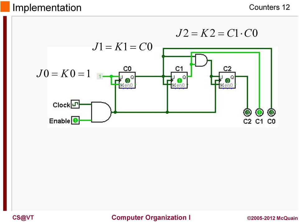
12 Implementation 2 J= K= C0 J 2= K 2= C C0 J 0= K0=
13 A mod-6 Counter 3 We can use JK flip-flops to implement a 4-bit counter: Note that the J and K inputs are all set to the fixed value, so the flip-flops "toggle". As the clock signal runs, the circuit will cycle its outputs through the values 0000, 000, 000,..., and then repeat the pattern. So, it counts clock ticks, modulo 6.

14 mod-6 Counter: first tick 4 Suppose the counter is in the initial state shown below (output is 0000). When the clock cycles from high to low: - the right-most sees its (inverted) clock signal go from low to high, and so it toggles its state to - the next flip-flop sees its clock signal go from high to low, and so it doesn't toggle - and so, neither do the other flip-flops So, the output is 000:

15 mod-6 Counter: second tick 5 Suppose the counter is now in the state shown below (output is 000). When the clock cycles from high to low (2 nd cycle): - the right-most sees its (inverted) clock signal go from low to high, and so it toggles its state to 0 - the next flip-flop sees its clock signal go from low to high, and so it toggles its state to - the next flip-flop sees its clock signal go from high to low, so it doesn't toggle So the output is 000.

16 mod-6 Counter: third tick 6 Suppose the counter is now in the state shown below (output is 000). When the clock cycles from high to low (3rd cycle): - the right-most sees its (inverted) clock signal go from low to high, and so it toggles its state to - the next flip-flop sees its clock signal go from high to low, and so it doesn't toggle So the output is 00.

17 mod-6 Counter: fourth tick 7 Suppose the counter is now in the state shown below (output is 00). When the clock cycles from high to low (4th cycle): - the right-most sees its (inverted) clock signal go from low to high, and so it toggles its state to 0 - the next flip-flop sees its clock signal go from low to high, and so it toggles its state to 0 - the next flip-flop sees its clock signal go from low to high, and so it toggles its state to So the output is 000.

DIGITAL COUNTERS. Q B Q A = 00 initially. Q B Q A = 01 after the first clock pulse.
 DIGITAL COUNTERS http://www.tutorialspoint.com/computer_logical_organization/digital_counters.htm Copyright tutorialspoint.com Counter is a sequential circuit. A digital circuit which is used for a counting
To design digital counter circuits using JK-Flip-Flop. To implement counter using 74LS193 IC.
 8.1 Objectives To design digital counter circuits using JK-Flip-Flop. To implement counter using 74LS193 IC. 8.2 Introduction Circuits for counting events are frequently used in computers and other digital
Module 3: Floyd, Digital Fundamental
 Module 3: Lecturer : Yongsheng Gao Room : Tech - 3.25 Email : yongsheng.gao@griffith.edu.au Structure : 6 lectures 1 Tutorial Assessment: 1 Laboratory (5%) 1 Test (20%) Textbook : Floyd, Digital Fundamental
Lecture 8: Synchronous Digital Systems
 Lecture 8: Synchronous Digital Systems The distinguishing feature of a synchronous digital system is that the circuit only changes in response to a system clock. For example, consider the edge triggered
CHAPTER 11 LATCHES AND FLIP-FLOPS
 CHAPTER 11 LATCHES AND FLIP-FLOPS This chapter in the book includes: Objectives Study Guide 11.1 Introduction 11.2 Set-Reset Latch 11.3 Gated D Latch 11.4 Edge-Triggered D Flip-Flop 11.5 S-R Flip-Flop
Counters and Decoders
 Physics 3330 Experiment #10 Fall 1999 Purpose Counters and Decoders In this experiment, you will design and construct a 4-bit ripple-through decade counter with a decimal read-out display. Such a counter
Flip-Flops and Sequential Circuit Design. ECE 152A Winter 2012
 Flip-Flops and Sequential Circuit Design ECE 52 Winter 22 Reading ssignment Brown and Vranesic 7 Flip-Flops, Registers, Counters and a Simple Processor 7.5 T Flip-Flop 7.5. Configurable Flip-Flops 7.6
Flip-Flops and Sequential Circuit Design
 Flip-Flops and Sequential Circuit Design ECE 52 Winter 22 Reading ssignment Brown and Vranesic 7 Flip-Flops, Registers, Counters and a Simple Processor 7.5 T Flip-Flop 7.5. Configurable Flip-Flops 7.6
ECE380 Digital Logic
 ECE38 igital Logic Flip-Flops, Registers and Counters: Flip-Flops r.. J. Jackson Lecture 25- Flip-flops The gated latch circuits presented are level sensitive and can change states more than once during
Counters & Shift Registers Chapter 8 of R.P Jain
 Chapter 3 Counters & Shift Registers Chapter 8 of R.P Jain Counters & Shift Registers Counters, Syllabus Design of Modulo-N ripple counter, Up-Down counter, design of synchronous counters with and without
CHAPTER IX REGISTER BLOCKS COUNTERS, SHIFT, AND ROTATE REGISTERS
 CHAPTER IX-1 CHAPTER IX CHAPTER IX COUNTERS, SHIFT, AN ROTATE REGISTERS REA PAGES 249-275 FROM MANO AN KIME CHAPTER IX-2 INTROUCTION -INTROUCTION Like combinational building blocks, we can also develop
Lesson 12 Sequential Circuits: Flip-Flops
 Lesson 12 Sequential Circuits: Flip-Flops 1. Overview of a Synchronous Sequential Circuit We saw from last lesson that the level sensitive latches could cause instability in a sequential system. This instability
Take-Home Exercise. z y x. Erik Jonsson School of Engineering and Computer Science. The University of Texas at Dallas
 Take-Home Exercise Assume you want the counter below to count mod-6 backward. That is, it would count 0-5-4-3-2-1-0, etc. Assume it is reset on startup, and design the wiring to make the counter count
Digital Logic Design Sequential circuits
 Digital Logic Design Sequential circuits Dr. Eng. Ahmed H. Madian E-mail: ahmed.madian@guc.edu.eg Dr. Eng. Rania.Swief E-mail: rania.swief@guc.edu.eg Dr. Eng. Ahmed H. Madian Registers An n-bit register
So far we have investigated combinational logic for which the output of the logic devices/circuits depends only on the present state of the inputs.
 equential Logic o far we have investigated combinational logic for which the output of the logic devices/circuits depends only on the present state of the inputs. In sequential logic the output of the
Having read this workbook you should be able to: recognise the arrangement of NAND gates used to form an S-R flip-flop.
 Objectives Having read this workbook you should be able to: recognise the arrangement of NAND gates used to form an S-R flip-flop. describe how such a flip-flop can be SET and RESET. describe the disadvantage
Decimal Number (base 10) Binary Number (base 2)
 Binary Number (base 2)") LECTURE 5. BINARY COUNTER Before starting with counters there is some vital information that needs to be understood. The most important is the fact that since the outputs of a digital chip can only be
LECTURE 5. BINARY COUNTER Before starting with counters there is some vital information that needs to be understood. The most important is the fact that since the outputs of a digital chip can only be
Design Example: Counters. Design Example: Counters. 3-Bit Binary Counter. 3-Bit Binary Counter. Other useful counters:
 Design Eample: ers er: a sequential circuit that repeats a specified sequence of output upon clock pulses. A,B,C,, Z. G, O, T, E, R, P, S,!.,,,,,,,7. 7,,,,,,,.,,,,,,,,,,,. Binary counter: follows the binary
DIGITAL ELECTRONICS. Counters. By: Electrical Engineering Department
 Counters By: Electrical Engineering Department 1 Counters Upon completion of the chapter, students should be able to:.1 Understand the basic concepts of asynchronous counter and synchronous counters, and
ENEE 244 (01**). Spring 2006. Homework 5. Due back in class on Friday, April 28.
. Spring 2006. Homework 5. Due back in class on Friday, April 28.") ENEE 244 (01**). Spring 2006 Homework 5 Due back in class on Friday, April 28. 1. Fill up the function table (truth table) for the following latch. How is this latch related to those described in the lectures
ENEE 244 (01**). Spring 2006 Homework 5 Due back in class on Friday, April 28. 1. Fill up the function table (truth table) for the following latch. How is this latch related to those described in the lectures
WEEK 8.1 Registers and Counters. ECE124 Digital Circuits and Systems Page 1
 WEEK 8.1 egisters and Counters ECE124 igital Circuits and Systems Page 1 Additional schematic FF symbols Active low set and reset signals. S Active high set and reset signals. S ECE124 igital Circuits
Chapter 8. Sequential Circuits for Registers and Counters
 Chapter 8 Sequential Circuits for Registers and Counters Lesson 3 COUNTERS Ch16L3- "Digital Principles and Design", Raj Kamal, Pearson Education, 2006 2 Outline Counters T-FF Basic Counting element State
Engr354: Digital Logic Circuits
 Engr354: igital Circuits Chapter 7 Sequential Elements r. Curtis Nelson Sequential Elements In this chapter you will learn about: circuits that can store information; Basic cells, latches, and flip-flops;
Contents COUNTER. Unit III- Counters
 COUNTER Contents COUNTER...1 Frequency Division...2 Divide-by-2 Counter... 3 Toggle Flip-Flop...3 Frequency Division using Toggle Flip-flops...5 Truth Table for a 3-bit Asynchronous Up Counter...6 Modulo
Sequential Logic Design Principles.Latches and Flip-Flops
 Sequential Logic Design Principles.Latches and Flip-Flops Doru Todinca Department of Computers Politehnica University of Timisoara Outline Introduction Bistable Elements Latches and Flip-Flops S-R Latch
Experiment # 9. Clock generator circuits & Counters. Eng. Waleed Y. Mousa
 Experiment # 9 Clock generator circuits & Counters Eng. Waleed Y. Mousa 1. Objectives: 1. Understanding the principles and construction of Clock generator. 2. To be familiar with clock pulse generation
Asynchronous Counters. Asynchronous Counters
 Counters and State Machine Design November 25 Asynchronous Counters ENGI 25 ELEC 24 Asynchronous Counters The term Asynchronous refers to events that do not occur at the same time With respect to counter
Registers & Counters
 Objectives This section deals with some simple and useful sequential circuits. Its objectives are to: Introduce registers as multi-bit storage devices. Introduce counters by adding logic to registers implementing
ETEC 2301 Programmable Logic Devices. Chapter 10 Counters. Shawnee State University Department of Industrial and Engineering Technologies
 ETEC 2301 Programmable Logic Devices Chapter 10 Counters Shawnee State University Department of Industrial and Engineering Technologies Copyright 2007 by Janna B. Gallaher Asynchronous Counter Operation
CS311 Lecture: Sequential Circuits
 CS311 Lecture: Sequential Circuits Last revised 8/15/2007 Objectives: 1. To introduce asynchronous and synchronous flip-flops (latches and pulsetriggered, plus asynchronous preset/clear) 2. To introduce
7. Latches and Flip-Flops
 Chapter 7 Latches and Flip-Flops Page 1 of 18 7. Latches and Flip-Flops Latches and flip-flops are the basic elements for storing information. One latch or flip-flop can store one bit of information. The
Memory Elements. Combinational logic cannot remember
 Memory Elements Combinational logic cannot remember Output logic values are function of inputs only Feedback is needed to be able to remember a logic value Memory elements are needed in most digital logic
Flip-Flops, Registers, Counters, and a Simple Processor
 June 8, 22 5:56 vra235_ch7 Sheet number Page number 349 black chapter 7 Flip-Flops, Registers, Counters, and a Simple Processor 7. Ng f3, h7 h6 349 June 8, 22 5:56 vra235_ch7 Sheet number 2 Page number
Counters are sequential circuits which "count" through a specific state sequence.
 Counters Counters are sequential circuits which "count" through a specific state sequence. They can count up, count down, or count through other fixed sequences. Two distinct types are in common usage:
Sequential Logic. (Materials taken from: Principles of Computer Hardware by Alan Clements )
") Sequential Logic (Materials taken from: Principles of Computer Hardware by Alan Clements ) Sequential vs. Combinational Circuits Combinatorial circuits: their outputs are computed entirely from their present
Sequential Logic (Materials taken from: Principles of Computer Hardware by Alan Clements ) Sequential vs. Combinational Circuits Combinatorial circuits: their outputs are computed entirely from their present
The components. E3: Digital electronics. Goals:
 E3: Digital electronics Goals: Basic understanding of logic circuits. Become familiar with the most common digital components and their use. Equipment: 1 st. LED bridge 1 st. 7-segment display. 2 st. IC
SEQUENTIAL CIRCUITS. Block diagram. Flip Flop. S-R Flip Flop. Block Diagram. Circuit Diagram
 SEQUENTIAL CIRCUITS http://www.tutorialspoint.com/computer_logical_organization/sequential_circuits.htm Copyright tutorialspoint.com The combinational circuit does not use any memory. Hence the previous
DIGITAL TECHNICS II. Dr. Bálint Pődör. Óbuda University, Microelectronics and Technology Institute. 2nd (Spring) term 2012/2013
 term 2012/2013") DIGITAL TECHNICS II Dr. Bálint Pődör Óbuda University, Microelectronics and Technology Institute 4. LECTURE: COUNTERS AND RELATED 2nd (Spring) term 2012/2013 1 4. LECTURE: COUNTERS AND RELATED 1. Counters,
DIGITAL TECHNICS II Dr. Bálint Pődör Óbuda University, Microelectronics and Technology Institute 4. LECTURE: COUNTERS AND RELATED 2nd (Spring) term 2012/2013 1 4. LECTURE: COUNTERS AND RELATED 1. Counters,
Asynchronous counters, except for the first block, work independently from a system clock.
 Counters Some digital circuits are designed for the purpose of counting and this is when counters become useful. Counters are made with flip-flops, they can be asynchronous or synchronous and they can
EE 42/100 Lecture 24: Latches and Flip Flops. Rev B 4/21/2010 (2:04 PM) Prof. Ali M. Niknejad
 Prof. Ali M. Niknejad") A. M. Niknejad University of California, Berkeley EE 100 / 42 Lecture 24 p. 1/20 EE 42/100 Lecture 24: Latches and Flip Flops ELECTRONICS Rev B 4/21/2010 (2:04 PM) Prof. Ali M. Niknejad University of California,
A. M. Niknejad University of California, Berkeley EE 100 / 42 Lecture 24 p. 1/20 EE 42/100 Lecture 24: Latches and Flip Flops ELECTRONICS Rev B 4/21/2010 (2:04 PM) Prof. Ali M. Niknejad University of California,
The 104 Duke_ACC Machine
 The 104 Duke_ACC Machine The goal of the next two lessons is to design and simulate a simple accumulator-based processor. The specifications for this processor and some of the QuartusII design components
3.Basic Gate Combinations
 3.Basic Gate Combinations 3.1 TTL NAND Gate In logic circuits transistors play the role of switches. For those in the TTL gate the conducting state (on) occurs when the baseemmiter signal is high, and
CDA 3200 Digital Systems. Instructor: Dr. Janusz Zalewski Developed by: Dr. Dahai Guo Spring 2012
 CDA 3200 Digital Systems Instructor: Dr. Janusz Zalewski Developed by: Dr. Dahai Guo Spring 2012 Outline SR Latch D Latch Edge-Triggered D Flip-Flop (FF) S-R Flip-Flop (FF) J-K Flip-Flop (FF) T Flip-Flop
DIGITAL TECHNICS II. Dr. Bálint Pődör. Óbuda University, Microelectronics and Technology Institute
 DIGITAL TECHNICS II Dr. Bálint Pődör Óbuda University, Microelectronics and Technology Institute 2. LECTURE: ELEMENTARY SEUENTIAL CIRCUITS: FLIP-FLOPS 1st year BSc course 2nd (Spring) term 2012/2013 1
Combinational Logic Design Process
 Combinational Logic Design Process Create truth table from specification Generate K-maps & obtain logic equations Draw logic diagram (sharing common gates) Simulate circuit for design verification Debug
BINARY CODED DECIMAL: B.C.D.
 BINARY CODED DECIMAL: B.C.D. ANOTHER METHOD TO REPRESENT DECIMAL NUMBERS USEFUL BECAUSE MANY DIGITAL DEVICES PROCESS + DISPLAY NUMBERS IN TENS IN BCD EACH NUMBER IS DEFINED BY A BINARY CODE OF 4 BITS.
Digital Logic Design. Basics Combinational Circuits Sequential Circuits. Pu-Jen Cheng
 Digital Logic Design Basics Combinational Circuits Sequential Circuits Pu-Jen Cheng Adapted from the slides prepared by S. Dandamudi for the book, Fundamentals of Computer Organization and Design. Introduction
Counters. Present State Next State A B A B 0 0 0 1 0 1 1 0 1 0 1 1 1 1 0 0
 ounter ounters ounters are a specific type of sequential circuit. Like registers, the state, or the flip-flop values themselves, serves as the output. The output value increases by one on each clock cycle.
Gates, Plexers, Decoders, Registers, Addition and Comparison
 Introduction to Digital Logic Autumn 2008 Gates, Plexers, Decoders, Registers, Addition and Comparison karl.marklund@it.uu.se ...open up a command shell and type logisim and press enter to start Logisim.
CSE140: Components and Design Techniques for Digital Systems
 CE4: Components and esign Techniques for igital ystems Tajana imunic osing ources: Where we are now What we ve covered so far (Chap -5, App. A& B) Number representations Boolean algebra OP and PO Logic
Upon completion of unit 1.1, students will be able to
 Upon completion of unit 1.1, students will be able to 1. Demonstrate safety of the individual, class, and overall environment of the classroom/laboratory, and understand that electricity, even at the nominal
Digital Systems Based on Principles and Applications of Electrical Engineering/Rizzoni (McGraw Hill
 Digital Systems Based on Principles and Applications of Electrical Engineering/Rizzoni (McGraw Hill Objectives: Analyze the operation of sequential logic circuits. Understand the operation of digital counters.
Latches, the D Flip-Flop & Counter Design. ECE 152A Winter 2012
 Latches, the D Flip-Flop & Counter Design ECE 52A Winter 22 Reading Assignment Brown and Vranesic 7 Flip-Flops, Registers, Counters and a Simple Processor 7. Basic Latch 7.2 Gated SR Latch 7.2. Gated SR
(Refer Slide Time: 00:01:16 min)
") Digital Computer Organization Prof. P. K. Biswas Department of Electronic & Electrical Communication Engineering Indian Institute of Technology, Kharagpur Lecture No. # 04 CPU Design: Tirning & Control
Digital Computer Organization Prof. P. K. Biswas Department of Electronic & Electrical Communication Engineering Indian Institute of Technology, Kharagpur Lecture No. # 04 CPU Design: Tirning & Control
EXPERIMENT 8. Flip-Flops and Sequential Circuits
 EXPERIMENT 8. Flip-Flops and Sequential Circuits I. Introduction I.a. Objectives The objective of this experiment is to become familiar with the basic operational principles of flip-flops and counters.
IE1204 Digital Design F12: Asynchronous Sequential Circuits (Part 1)
") IE1204 Digital Design F12: Asynchronous Sequential Circuits (Part 1) Elena Dubrova KTH / ICT / ES dubrova@kth.se BV pp. 584-640 This lecture IE1204 Digital Design, HT14 2 Asynchronous Sequential Machines
IE1204 Digital Design F12: Asynchronous Sequential Circuits (Part 1) Elena Dubrova KTH / ICT / ES dubrova@kth.se BV pp. 584-640 This lecture IE1204 Digital Design, HT14 2 Asynchronous Sequential Machines
Chapter 4 Register Transfer and Microoperations. Section 4.1 Register Transfer Language
 Chapter 4 Register Transfer and Microoperations Section 4.1 Register Transfer Language Digital systems are composed of modules that are constructed from digital components, such as registers, decoders,
Digital Fundamentals. Lab 8 Asynchronous Counter Applications
 Richland College Engineering Technology Rev. 0 B. Donham Rev. 1 (7/2003). Horne Rev. 2 (1/2008). Bradbury Digital Fundamentals CETT 1425 Lab 8 Asynchronous Counter Applications Name: Date: Objectives:
1.1 The 7493 consists of 4 flip-flops with J-K inputs unconnected. In a TTL chip, unconnected inputs
 CALIFORNIA STATE UNIVERSITY LOS ANGELES Department of Electrical and Computer Engineering EE-246 Digital Logic Lab EXPERIMENT 1 COUNTERS AND WAVEFORMS Text: Mano, Digital Design, 3rd & 4th Editions, Sec.
CHAPTER 3 Boolean Algebra and Digital Logic
 CHAPTER 3 Boolean Algebra and Digital Logic 3.1 Introduction 121 3.2 Boolean Algebra 122 3.2.1 Boolean Expressions 123 3.2.2 Boolean Identities 124 3.2.3 Simplification of Boolean Expressions 126 3.2.4
Reading 13 : Finite State Automata and Regular Expressions
 CS/Math 24: Introduction to Discrete Mathematics Fall 25 Reading 3 : Finite State Automata and Regular Expressions Instructors: Beck Hasti, Gautam Prakriya In this reading we study a mathematical model
[ 4 ] Logic Symbols and Truth Table
![[ 4 ] Logic Symbols and Truth Table](/thumbs/40/21640854.jpg "[ 4 ] Logic Symbols and Truth Table") [ 4 ] Logic s and Truth Table 1. How to Read MIL-Type Logic s Table 1.1 shows the MIL-type logic symbols used for high-speed CMO ICs. This logic chart is based on MIL-TD-806. The clocked inverter and transmission
[ 4 ] Logic s and Truth Table 1. How to Read MIL-Type Logic s Table 1.1 shows the MIL-type logic symbols used for high-speed CMO ICs. This logic chart is based on MIL-TD-806. The clocked inverter and transmission
Digital Electronics Detailed Outline
 Digital Electronics Detailed Outline Unit 1: Fundamentals of Analog and Digital Electronics (32 Total Days) Lesson 1.1: Foundations and the Board Game Counter (9 days) 1. Safety is an important concept
RETRIEVING DATA FROM THE DDC112
 RETRIEVING DATA FROM THE by Jim Todsen This application bulletin explains how to retrieve data from the. It elaborates on the discussion given in the data sheet and provides additional information to allow
Register File, Finite State Machines & Hardware Control Language
 Register File, Finite State Machines & Hardware Control Language Avin R. Lebeck Some slides based on those developed by Gershon Kedem, and by Randy Bryant and ave O Hallaron Compsci 04 Administrivia Homework
AC 2011-1060: ELECTRICAL ENGINEERING STUDENT SENIOR CAP- STONE PROJECT: A MOSIS FAST FOURIER TRANSFORM PROCES- SOR CHIP-SET
 AC 2011-1060: ELECTRICAL ENGINEERING STUDENT SENIOR CAP- STONE PROJECT: A MOSIS FAST FOURIER TRANSFORM PROCES- SOR CHIP-SET Peter M Osterberg, University of Portland Dr. Peter Osterberg is an associate
Digital Controller for Pedestrian Crossing and Traffic Lights
 Project Objective: - To design and simulate, a digital controller for traffic and pedestrian lights at a pedestrian crossing using Microsim Pspice The controller must be based on next-state techniques
LAB #4 Sequential Logic, Latches, Flip-Flops, Shift Registers, and Counters
 LAB #4 Sequential Logic, Latches, Flip-Flops, Shift Registers, and Counters LAB OBJECTIVES 1. Introduction to latches and the D type flip-flop 2. Use of actual flip-flops to help you understand sequential
Topics. Flip-flop-based sequential machines. Signals in flip-flop system. Flip-flop rules. Latch-based machines. Two-sided latch constraint
 Topics Flip-flop-based sequential machines! Clocking disciplines. Flip-flop rules! Primary inputs change after clock (φ) edge.! Primary inputs must stabilize before next clock edge.! Rules allow changes
Lecture-3 MEMORY: Development of Memory:
 Lecture-3 MEMORY: It is a storage device. It stores program data and the results. There are two kind of memories; semiconductor memories & magnetic memories. Semiconductor memories are faster, smaller,
CHAPTER 11: Flip Flops
 CHAPTER 11: Flip Flops In this chapter, you will be building the part of the circuit that controls the command sequencing. The required circuit must operate the counter and the memory chip. When the teach
Napier University. School of Engineering. Electronic Engineering A Module: SE42205 Digital Design
 Napier University School of Engineering Digital Design Clock + U1 out 5V "1" "2" "4" JK-FF D JK-FF C JK-FF B U8 SN7408 signal U4 SN74107 U5 SN74107 U6 SN74107 U3 SN7408 U2 J Q J Q & J Q & K CQ K CQ K CQ
MICROPROCESSOR. Exclusive for IACE Students www.iace.co.in iacehyd.blogspot.in Ph: 9700077455/422 Page 1
 MICROPROCESSOR A microprocessor incorporates the functions of a computer s central processing unit (CPU) on a single Integrated (IC), or at most a few integrated circuit. It is a multipurpose, programmable
Gray Code Generator and Decoder by Carsten Kristiansen Napier University. November 2004
 Gray Code Generator and Decoder by Carsten Kristiansen Napier University November 2004 Title page Author: Carsten Kristiansen. Napier No: 04007712. Assignment title: Design of a Gray Code Generator and
Gates, Circuits, and Boolean Algebra
 Gates, Circuits, and Boolean Algebra Computers and Electricity A gate is a device that performs a basic operation on electrical signals Gates are combined into circuits to perform more complicated tasks
150127-Microprocessor & Assembly Language
 Chapter 3 Z80 Microprocessor Architecture The Z 80 is one of the most talented 8 bit microprocessors, and many microprocessor-based systems are designed around the Z80. The Z80 microprocessor needs an
2 : BISTABLES. In this Chapter, you will find out about bistables which are the fundamental building blocks of electronic counting circuits.
 2 : BITABLE In this Chapter, you will find out about bistables which are the fundamental building blos of electronic counting circuits. et-reset bistable A bistable circuit, also called a latch, or flip-flop,
The enable pin needs to be high for data to be fed to the outputs Q and Q bar.
 of 7 -Type flip-flop (Toggle switch) The -type flip-flops are used in prescalar/divider circuits and frequency phase detectors. Figure shows how the flip-flop (latch) can be made using -input logic circuits
ASYNCHRONOUS COUNTERS
 LB no.. SYNCHONOUS COUNTES. Introduction Counters are sequential logic circuits that counts the pulses applied at their clock input. They usually have 4 bits, delivering at the outputs the corresponding
Lab #5: Design Example: Keypad Scanner and Encoder - Part 1 (120 pts)
") Dr. Greg Tumbush, gtumbush@uccs.edu Lab #5: Design Example: Keypad Scanner and Encoder - Part 1 (120 pts) Objective The objective of lab assignments 5 through 9 are to systematically design and implement
Dr. Greg Tumbush, gtumbush@uccs.edu Lab #5: Design Example: Keypad Scanner and Encoder - Part 1 (120 pts) Objective The objective of lab assignments 5 through 9 are to systematically design and implement
Lecture 12: More on Registers, Multiplexers, Decoders, Comparators and Wot- Nots
 Lecture 12: More on Registers, Multiplexers, Decoders, Comparators and Wot- Nots Registers As you probably know (if you don t then you should consider changing your course), data processing is usually
CSE140 Homework #7 - Solution
 CSE140 Spring2013 CSE140 Homework #7 - Solution You must SHOW ALL STEPS for obtaining the solution. Reporting the correct answer, without showing the work performed at each step will result in getting
Cascaded Counters. Page 1 BYU
 Cascaded Counters Page 1 Mod-N Counters Generally we are interested in counters that count up to specific count values Not just powers of 2 A mod-n counter has N states Counts from 0 to N-1 then rolls
Chapter 5. Sequential Logic
 Chapter 5 Sequential Logic Sequential Circuits (/2) Combinational circuits: a. contain no memory elements b. the outputs depends on the current inputs Sequential circuits: a feedback path outputs depends
Using Xilinx ISE for VHDL Based Design
 ECE 561 Project 4-1 - Using Xilinx ISE for VHDL Based Design In this project you will learn to create a design module from VHDL code. With Xilinx ISE, you can easily create modules from VHDL code using
Sequential Circuit Design
 Sequential Circuit Design Lan-Da Van ( 倫 ), Ph. D. Department of Computer Science National Chiao Tung University Taiwan, R.O.C. Fall, 2009 ldvan@cs.nctu.edu.tw http://www.cs.nctu.edu.tw/~ldvan/ Outlines
Figure 8-1 Four Possible Results of Adding Two Bits
 CHPTER EIGHT Combinational Logic pplications Thus far, our discussion has focused on the theoretical design issues of computer systems. We have not yet addressed any of the actual hardware you might find
3-Digit Counter and Display
 ECE 2B Winter 2007 Lab #7 7 3-Digit Counter and Display This final lab brings together much of what we have done in our lab experiments this quarter to construct a simple tachometer circuit for measuring
Chapter 2 Logic Gates and Introduction to Computer Architecture
 Chapter 2 Logic Gates and Introduction to Computer Architecture 2.1 Introduction The basic components of an Integrated Circuit (IC) is logic gates which made of transistors, in digital system there are
Fig1-1 2-bit asynchronous counter
 Digital electronics 1-Sequential circuit counters Such a group of flip- flops is a counter. The number of flip-flops used and the way in which they are connected determine the number of states and also
Chapter 9 Latches, Flip-Flops, and Timers
 ETEC 23 Programmable Logic Devices Chapter 9 Latches, Flip-Flops, and Timers Shawnee State University Department of Industrial and Engineering Technologies Copyright 27 by Janna B. Gallaher Latches A temporary
MULTIPLE CHOICE. Choose the one alternative that best completes the statement or answers the question.
 CHAPTER3 QUESTIONS MULTIPLE CHOICE. Choose the one alternative that best completes the statement or answers the question. ) If one input of an AND gate is LOW while the other is a clock signal, the output
DM74LS112A Dual Negative-Edge-Triggered Master-Slave J-K Flip-Flop with Preset, Clear, and Complementary Outputs
 August 1986 Revised March 2000 DM74LS112A Dual Negative-Edge-Triggered Master-Slave J-K Flip-Flop with Preset, Clear, and Complementary General Description This device contains two independent negative-edge-triggered
PROGETTO DI SISTEMI ELETTRONICI DIGITALI. Digital Systems Design. Digital Circuits Advanced Topics
 PROGETTO DI SISTEMI ELETTRONICI DIGITALI Digital Systems Design Digital Circuits Advanced Topics 1 Sequential circuit and metastability 2 Sequential circuit - FSM A Sequential circuit contains: Storage
Lab 11 Digital Dice. Figure 11.0. Digital Dice Circuit on NI ELVIS II Workstation
 Lab 11 Digital Dice Figure 11.0. Digital Dice Circuit on NI ELVIS II Workstation From the beginning of time, dice have been used for games of chance. Cubic dice similar to modern dice date back to before
Finite State Machine. RTL Hardware Design by P. Chu. Chapter 10 1
 Finite State Machine Chapter 10 1 Outline 1. Overview 2. FSM representation 3. Timing and performance of an FSM 4. Moore machine versus Mealy machine 5. VHDL description of FSMs 6. State assignment 7.
PURDUE UNIVERSITY NORTH CENTRAL
 ECET 109/159 PURDUE UNIVERSITY NORTH CENTRAL Electrical and Computer Engineering Technology Department All Semesters ECET Lab Report Format and Guidelines I. Introduction. Part of being technically educated
Binary Adders: Half Adders and Full Adders
 Binary Adders: Half Adders and Full Adders In this set of slides, we present the two basic types of adders: 1. Half adders, and 2. Full adders. Each type of adder functions to add two binary bits. In order
Wiki Lab Book. This week is practice for wiki usage during the project.
 Wiki Lab Book Use a wiki as a lab book. Wikis are excellent tools for collaborative work (i.e. where you need to efficiently share lots of information and files with multiple people). This week is practice