Analog Filters. A common instrumentation filter application is the attenuation of high frequencies to avoid frequency aliasing in the sampled data.
|
|
|
- Clemence Stephens
- 7 years ago
- Views:
Transcription
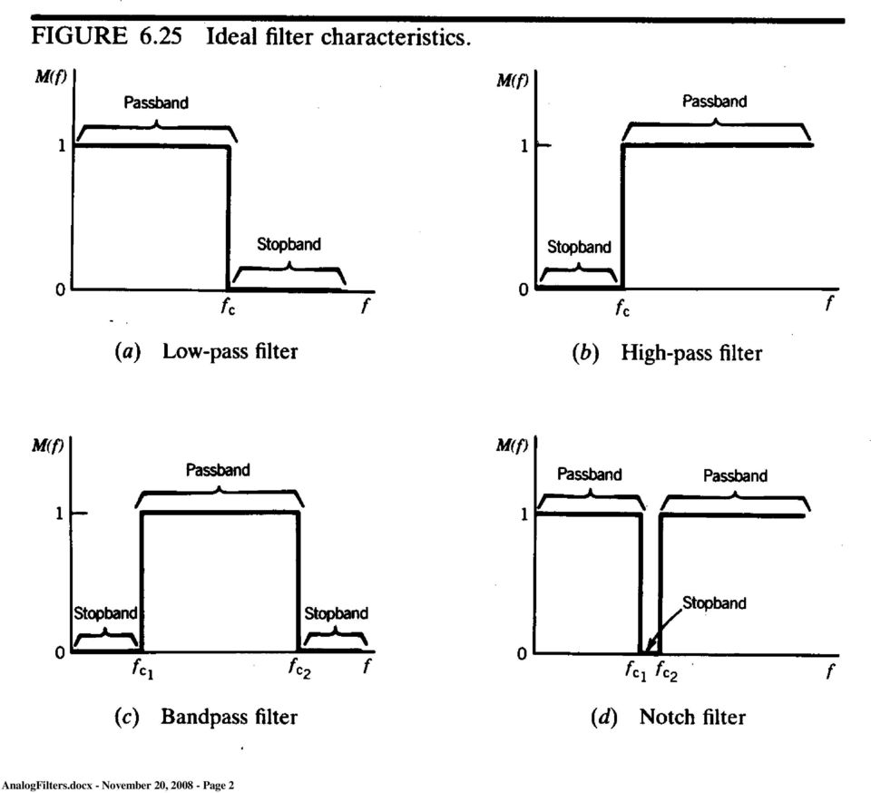
1 Analog Filters Filters can be used to attenuate unwanted signals such as interference or noise or to isolate desired signals from unwanted. They use the frequency response of a measuring system to alter the dynamic characteristics of a signal. A common instrumentation filter application is the attenuation of high frequencies to avoid frequency aliasing in the sampled data. Filters can be broadly classified as: Low-pass High-pass Band-pass Notch eliminate high frequency components. eliminate low frequency components. eliminate frequencies outside of a given range or band. eliminate frequencies in a given range or band. Simple first-order systems can be used as low-pass filters because they attenuate higher frequencies more than lower frequencies. The thermocouples used in the lab would respond poorly to high frequency (> 1 Hz) temperature fluctuations. AnalogFilters.docx - November 20, Page 1

2 AnalogFilters.docx - November 20, Page 2
3 AnalogFilters.docx - November 20, Page 3

4 Some examples of low-pass filters are given below: (Figure from Doebelin) AnalogFilters.docx - November 20, Page 4

5 1 M ( ) = (3.10) 2 1/ 2 1 ( ) 1 ( ) = tan (3.9) db= 20log M ( / 2 ) = 20log M ( f ) We can improve the roll-off characteristics of a lowpass filter by cascading several stages: AnalogFilters.docx - November 20, Page 5

6 Magnitude Ratio For the cascaded filter, the magnitude ratio and phase shift are: 1 M ( f ) = 2k [1 + ( f/ f 1/2 c) ] 1 2,3 (6.57, 6.60 ) ( f ) = ( f ) k i=1 i The magnitude ratio is plotted as a function of normalized frequency, f/f c where f c is the filter cutoff frequency, for values of k = 1, 2, 3, 4 and 5 below: Cascaded Butterworth Filtering Stage 2 Stage 3 Stage 4 Stage 5 Stage f/fc The phase shift is increased by the cascading, but that is usually not important. AnalogFilters.docx - November 20, Page 6

7 To keep the later filter stages from loading down the earlier ones, try putting a unity gain amplifier between them AnalogFilters.docx - November 20, Page 7

8 Here are some examples of high pass filters, from Doebelin: AnalogFilters.docx - November 20, Page 8

9 Cascading can also be used to improve the performance of high-pass filters: Figure 6.32 in 2 nd and 3 rd Edition The filters described above are all passive, that is they involve no external power supply. Improved performance can be obtained from active filters, which use operational amplifiers. Some examples are shown below: AnalogFilters.docx - November 20, Page 9

10 AnalogFilters.docx - November 20, Page 10

11 Comparison of Common Low Pass Filter Types Figure 3 From Filter Basics: Anti-Aliasing AnalogFilters.docx - November 20, Page 11

12 Key Features of Low Pass Filter Types a. Bessel: linear phase shift, gradual roll off b. Butterworth: Steeper roll off, nonlinear phase shift c. Chebyshev: Steep roll off, nonlinear phase shift, non-smooth pass band magnitude ratio d. Elliptic: very steep roll off, nonlinear phase shift, non-smooth pass band magnitude ratio. Example 6.6 Design a one-stage Butterworth RC Low-pass filter with a cutoff frequency of -3 db set at 100 Hz. KNOWN f c = 100 Hz, k = 1 M(100 Hz) = - 3 db =.707 FIND R, C and δ SOLUTION Remember = RC = 1/2f c for a single pole RC filter! therefore: f c = 1/2RC = 100 Hz RC = 1/200 = AnalogFilters.docx - November 20, Page 12
 = - 3 db =.")
13 EXAMPLE FINAL EXAM QUESTIONS: 1. Given a 1000 ohm resistor what size capacitor would be required to build a single pole Butterworth low pass filter with a cut off frequency of 100 Hz? a uf b. 5 uf c. 2.5 uf d. 100 uf 2. Which low pass filter type has the steepest magnitude ratio roll off? a. Bessel b. Butterworth c. Chebyshev d. Elliptic 3. Which low pass filter type has a linear phase shift? a. Bessel b. Butterworth c. Chebyshev d. Elliptic AnalogFilters.docx - November 20, Page 13

14 Digital Filtering As we have discussed earlier, any reasonably "well behaved" function can be written as a Fourier Series 2n t f ( t ) = Ansin + n i=0 T We can use the Fourier series representation to filter the original signal. For example, suppose we want to filter out all frequencies greater than 10 times the fundamental frequency. Defining a new function: 10 2n t f ( t ) = Ansin + n i=0 T f'(t) will contain all frequency components of f(t) which are 10 times the fundamental frequency. It will contain none of the higher frequency components. It is a perfect low pass filter. We can also use the Fourier series to produce a high pass filter. 2n t f ( t ) = Ansin + n i=11 T AnalogFilters.docx - November 20, Page 14

15 This will filter out everything with a frequency 10 times the fundamental. We can make a notch filter using: 9 2n t f ( t ) = Ansin + n i=1 T 2n t + Ansin + n i=11 T This will filter out everything with a frequency = 10 times the fundamental. Finally, a bandpass filter which will pass only the components with frequencies between 8 and 12 times the fundamental frequency is given by: 12 f t = A nt + n ( ) nsin i=8 AnalogFilters.docx - November 20, Page 15

16 The disadvantage of the Fourier Series method is the time required to calculate the series. In this form the method can't be used to filter data as it is obtained. A variety of Fast Fourier Transform methods have been developed for online filtering. Faster computers have also made digital filtering more practical. Of course, these methods work only for signals which can be digitized - usually electrical voltages. Example Given the hardware in our lab design a multi-stage lowpass Butterworth filter with a cutoff frequency of 1 khz that will attenuate an input signal to the level of the quantization noise above 2 khz? The input signal can be expressed as: Given the input signal the gain must be set to 1 to avoid clipping the ±6 volt signal. Therefore the quantization level is volts. The Butterworth filter magnitude ratio needed to reduce the 2000 Hz ±1 volt signal to ±½Q is Therefore At least a 10 stage filter would be required to attenuate the 2 khz signal to the level of the quantization noise. Due to the gradual roll off of Butterworth filters many stages are needed to produce an effective anti-aliasing filter. AnalogFilters.docx - November 20, Page 16

LAB 12: ACTIVE FILTERS
 A. INTRODUCTION LAB 12: ACTIVE FILTERS After last week s encounter with op- amps we will use them to build active filters. B. ABOUT FILTERS An electric filter is a frequency-selecting circuit designed
Filter Comparison. Match #1: Analog vs. Digital Filters
 CHAPTER 21 Filter Comparison Decisions, decisions, decisions! With all these filters to choose from, how do you know which to use? This chapter is a head-to-head competition between filters; we'll select
Laboratory #5: RF Filter Design
 EEE 194 RF Laboratory Exercise 5 1 Laboratory #5: RF Filter Design I. OBJECTIVES A. Design a third order low-pass Chebyshev filter with a cutoff frequency of 330 MHz and 3 db ripple with equal terminations
How to Design 10 khz filter. (Using Butterworth filter design) Application notes. By Vadim Kim
 Application notes. By Vadim Kim") How to Design 10 khz filter. (Using Butterworth filter design) Application notes. By Vadim Kim This application note describes how to build a 5 th order low pass, high pass Butterworth filter for 10 khz
How to Design 10 khz filter. (Using Butterworth filter design) Application notes. By Vadim Kim This application note describes how to build a 5 th order low pass, high pass Butterworth filter for 10 khz
Analog and Digital Filters Anthony Garvert November 13, 2015
 Analog and Digital Filters Anthony Garvert November 13, 2015 Abstract In circuit analysis and performance, a signal transmits some form of information, such as a voltage or current. However, over a range
Analog signals are those which are naturally occurring. Any analog signal can be converted to a digital signal.
 3.3 Analog to Digital Conversion (ADC) Analog signals are those which are naturally occurring. Any analog signal can be converted to a digital signal. 1 3.3 Analog to Digital Conversion (ADC) WCB/McGraw-Hill
CHAPTER 6 Frequency Response, Bode Plots, and Resonance
 ELECTRICAL CHAPTER 6 Frequency Response, Bode Plots, and Resonance 1. State the fundamental concepts of Fourier analysis. 2. Determine the output of a filter for a given input consisting of sinusoidal
Lab #9: AC Steady State Analysis
 Theory & Introduction Lab #9: AC Steady State Analysis Goals for Lab #9 The main goal for lab 9 is to make the students familar with AC steady state analysis, db scale and the NI ELVIS frequency analyzer.
Sophomore Physics Laboratory (PH005/105)
") CALIFORNIA INSTITUTE OF TECHNOLOGY PHYSICS MATHEMATICS AND ASTRONOMY DIVISION Sophomore Physics Laboratory (PH5/15) Analog Electronics Active Filters Copyright c Virgínio de Oliveira Sannibale, 23 (Revision
CALIFORNIA INSTITUTE OF TECHNOLOGY PHYSICS MATHEMATICS AND ASTRONOMY DIVISION Sophomore Physics Laboratory (PH5/15) Analog Electronics Active Filters Copyright c Virgínio de Oliveira Sannibale, 23 (Revision
LM833,LMF100,MF10. Application Note 779 A Basic Introduction to Filters - Active, Passive,and. Switched Capacitor. Literature Number: SNOA224A
 LM833,LMF100,MF10 Application Note 779 A Basic Introduction to Filters - Active, Passive,and Switched Capacitor Literature Number: SNOA224A A Basic Introduction to Filters Active, Passive, and Switched-Capacitor
NAPIER University School of Engineering. Electronic Systems Module : SE32102 Analogue Filters Design And Simulation. 4 th order Butterworth response
 NAPIER University School of Engineering Electronic Systems Module : SE32102 Analogue Filters Design And Simulation. 4 th order Butterworth response In R1 R2 C2 C1 + Opamp A - R1 R2 C2 C1 + Opamp B - Out
SUMMARY. Additional Digital/Software filters are included in Chart and filter the data after it has been sampled and recorded by the PowerLab.
 This technique note was compiled by ADInstruments Pty Ltd. It includes figures and tables from S.S. Young (2001): Computerized data acquisition and analysis for the life sciences. For further information
FAST Fourier Transform (FFT) and Digital Filtering Using LabVIEW
 and Digital Filtering Using LabVIEW") FAST Fourier Transform (FFT) and Digital Filtering Using LabVIEW Wei Lin Department of Biomedical Engineering Stony Brook University Instructor s Portion Summary This experiment requires the student to
FAST Fourier Transform (FFT) and Digital Filtering Using LabVIEW Wei Lin Department of Biomedical Engineering Stony Brook University Instructor s Portion Summary This experiment requires the student to
CHAPTER 8 ANALOG FILTERS
 ANALOG FILTERS CHAPTER 8 ANALOG FILTERS SECTION 8.: INTRODUCTION 8. SECTION 8.2: THE TRANSFER FUNCTION 8.5 THE SPLANE 8.5 F O and Q 8.7 HIGHPASS FILTER 8.8 BANDPASS FILTER 8.9 BANDREJECT (NOTCH) FILTER
CTCSS REJECT HIGH PASS FILTERS IN FM RADIO COMMUNICATIONS AN EVALUATION. Virgil Leenerts WØINK 8 June 2008
 CTCSS REJECT HIGH PASS FILTERS IN FM RADIO COMMUNICATIONS AN EVALUATION Virgil Leenerts WØINK 8 June 28 The response of the audio voice band high pass filter is evaluated in conjunction with the rejection
Selected Filter Circuits Dr. Lynn Fuller
 ROCHESTER INSTITUTE OF TECHNOLOGY MICROELECTRONIC ENGINEERING Selected Filter Circuits Dr. Lynn Fuller Webpage: http://people.rit.edu/lffeee 82 Lomb Memorial Drive Rochester, NY 146235604 Tel (585) 4752035
A Basic Introduction to Filters Active Passive and Switched-Capacitor
 A Basic Introduction to Filters Active Passive and Switched-Capacitor 1 0 INTRODUCTION Filters of some sort are essential to the operation of most electronic circuits It is therefore in the interest of
An Adjustable Audio Filter System for the Receiver - Part 1
 1 of 7 An Adjustable Audio Filter System for the Receiver - Part 1 The audio response is shaped as required using Switched Capacitor Filters Lloyd Butler VK5BR Front panel view of the original receiver
More Filter Design on a Budget
 Application Report SLOA096 December 2001 More Filter Design on a Budget Bruce Carter High Performance Linear Products ABSTRACT This document describes filter design from the standpoint of cost. Filter
1995 Mixed-Signal Products SLAA013
 Application Report 995 Mixed-Signal Products SLAA03 IMPORTANT NOTICE Texas Instruments and its subsidiaries (TI) reserve the right to make changes to their products or to discontinue any product or service
2.161 Signal Processing: Continuous and Discrete Fall 2008
 MT OpenCourseWare http://ocw.mit.edu.6 Signal Processing: Continuous and Discrete Fall 00 For information about citing these materials or our Terms of Use, visit: http://ocw.mit.edu/terms. MASSACHUSETTS
Time series analysis Matlab tutorial. Joachim Gross
 Time series analysis Matlab tutorial Joachim Gross Outline Terminology Sampling theorem Plotting Baseline correction Detrending Smoothing Filtering Decimation Remarks Focus on practical aspects, exercises,
Introduction to Digital Filters
 CHAPTER 14 Introduction to Digital Filters Digital filters are used for two general purposes: (1) separation of signals that have been combined, and (2) restoration of signals that have been distorted
Em bedded DSP : I ntroduction to Digital Filters
 Embedded DSP : Introduction to Digital Filters 1 Em bedded DSP : I ntroduction to Digital Filters Digital filters are a important part of DSP. In fact their extraordinary performance is one of the keys
Frequency Response of Filters
 School of Engineering Department of Electrical and Computer Engineering 332:224 Principles of Electrical Engineering II Laboratory Experiment 2 Frequency Response of Filters 1 Introduction Objectives To
Chapter 16. Active Filter Design Techniques. Excerpted from Op Amps for Everyone. Literature Number SLOA088. Literature Number: SLOD006A
 hapter 16 Active Filter Design Techniques Literature Number SLOA088 Excerpted from Op Amps for Everyone Literature Number: SLOD006A hapter 16 Active Filter Design Techniques Thomas Kugelstadt 16.1 Introduction
Using the Texas Instruments Filter Design Database
 Application Report SLOA062 July, 2001 Bruce Carter Using the Texas Instruments Filter Design Database High Performance Linear Products ABSTRACT Texas Instruments applications personnel have decades of
A Single-Supply Op-Amp Circuit Collection
 Application Report SLOA058 November 2000 A SingleSupply OpAmp Circuit Collection Bruce Carter OpAmp Applications, High Performance Linear Products One of the biggest problems for designers of opamp circuitry
APPLICATION BULLETIN
 APPLICATION BULLETIN Mailing Address: PO Box 400 Tucson, AZ 8574 Street Address: 670 S. Tucson Blvd. Tucson, AZ 85706 Tel: (602) 746- Twx: 90-952- Telex: 066-649 FAX (602) 889-50 Immediate Product Info:
MATRIX TECHNICAL NOTES
 200 WOOD AVENUE, MIDDLESEX, NJ 08846 PHONE (732) 469-9510 FAX (732) 469-0418 MATRIX TECHNICAL NOTES MTN-107 TEST SETUP FOR THE MEASUREMENT OF X-MOD, CTB, AND CSO USING A MEAN SQUARE CIRCUIT AS A DETECTOR
Chapter 12: The Operational Amplifier
 Chapter 12: The Operational Amplifier 12.1: Introduction to Operational Amplifier (Op-Amp) Operational amplifiers (op-amps) are very high gain dc coupled amplifiers with differential inputs; they are used
Lock - in Amplifier and Applications
 Lock - in Amplifier and Applications What is a Lock in Amplifier? In a nut shell, what a lock-in amplifier does is measure the amplitude V o of a sinusoidal voltage, V in (t) = V o cos(ω o t) where ω o
*For stability of the feedback loop, the differential gain must vary as
 ECE137a Lab project 3 You will first be designing and building an op-amp. The op-amp will then be configured as a narrow-band amplifier for amplification of voice signals in a public address system. Part
ADC and DAC. Quantization
 CHAPTER ADC and DAC Most of the signals directly encountered in science and engineering are continuous: light intensity that changes with distance; voltage that varies over time; a chemical reaction rate
FEATURES APPLICATIO S TYPICAL APPLICATIO. LTC1061 High Performance Triple Universal Filter Building Block DESCRIPTIO
 FEATRES Three Filters in a Single Package p to th Order Filter Functions Center Frequency Range up to khz f O Q Product up to MHz Guaranteed Center Frequency and Q Accuracy Over Temperature Guaranteed
Application Report SLOA024B
 Application Report July 999 Revised September 2002 Mixed Signal Products SLOA024B IMPORTANT NOTICE Texas Instruments Incorporated and its subsidiaries (TI) reserve the right to make corrections, modifications,
Making Accurate Voltage Noise and Current Noise Measurements on Operational Amplifiers Down to 0.1Hz
 Author: Don LaFontaine Making Accurate Voltage Noise and Current Noise Measurements on Operational Amplifiers Down to 0.1Hz Abstract Making accurate voltage and current noise measurements on op amps in
ANALYZER BASICS WHAT IS AN FFT SPECTRUM ANALYZER? 2-1
 WHAT IS AN FFT SPECTRUM ANALYZER? ANALYZER BASICS The SR760 FFT Spectrum Analyzer takes a time varying input signal, like you would see on an oscilloscope trace, and computes its frequency spectrum. Fourier's
Common Emitter BJT Amplifier Design Current Mirror Design
 Common Emitter BJT Amplifier Design Current Mirror Design 1 Some Random Observations Conditions for stabilized voltage source biasing Emitter resistance, R E, is needed. Base voltage source will have finite
University of Rochester Department of Electrical and Computer Engineering ECE113 Lab. #7 Higher-order filter & amplifier designs March, 2012
 University of Rochester Department of Electrical and Computer Engineering ECE113 Lab. #7 Higherorder filter & amplifier designs March, 2012 Writeups, due one week after the lab is performed, should provide
isim ACTIVE FILTER DESIGNER NEW, VERY CAPABLE, MULTI-STAGE ACTIVE FILTER DESIGN TOOL
 isim ACTIVE FILTER DESIGNER NEW, VERY CAPABLE, MULTI-STAGE ACTIVE FILTER DESIGN TOOL Michael Steffes Sr. Applications Manager 12/15/2010 SIMPLY SMARTER Introduction to the New Active Filter Designer Scope
AN-837 APPLICATION NOTE
 APPLICATION NOTE One Technology Way P.O. Box 916 Norwood, MA 262-916, U.S.A. Tel: 781.329.47 Fax: 781.461.3113 www.analog.com DDS-Based Clock Jitter Performance vs. DAC Reconstruction Filter Performance
PHYSICS 360 - LAB #2 Passive Low-pass and High-pass Filter Circuits and Integrator and Differentiator Circuits
 PHYSICS 360 - LAB #2 Passie Low-pass and High-pass Filter Circuits and Integrator and Differentiator Circuits Objectie: Study the behaior of low-pass and high-pass filters. Study the differentiator and
The Calculation of G rms
 The Calculation of G rms QualMark Corp. Neill Doertenbach The metric of G rms is typically used to specify and compare the energy in repetitive shock vibration systems. However, the method of arriving
chapter Introduction to Digital Signal Processing and Digital Filtering 1.1 Introduction 1.2 Historical Perspective
 Introduction to Digital Signal Processing and Digital Filtering chapter 1 Introduction to Digital Signal Processing and Digital Filtering 1.1 Introduction Digital signal processing (DSP) refers to anything
6 Output With 1 kω in Series Between the Output and Analyzer... 7 7 Output With RC Low-Pass Filter (1 kω and 4.7 nf) in Series Between the Output
 in Series Between the Output") Application Report SLAA313 December 26 Out-of-Band Noise Measurement Issues for Audio Codecs Greg Hupp... Data Acquisition Products ABSTRACT This report discusses the phenomenon of out-of-band noise, and
Application Report SLAA313 December 26 Out-of-Band Noise Measurement Issues for Audio Codecs Greg Hupp... Data Acquisition Products ABSTRACT This report discusses the phenomenon of out-of-band noise, and
Kit 106. 50 Watt Audio Amplifier
 Kit 106 50 Watt Audio Amplifier T his kit is based on an amazing IC amplifier module from ST Electronics, the TDA7294 It is intended for use as a high quality audio class AB amplifier in hi-fi applications
Digital Signal Processing IIR Filter Design via Impulse Invariance
 Digital Signal Processing IIR Filter Design via Impulse Invariance D. Richard Brown III D. Richard Brown III 1 / 11 Basic Procedure We assume here that we ve already decided to use an IIR filter. The basic
Tutorial www.loudsoft.com
 Tutorial www.loudsoft.com In this tutorial we show several examples of simple and advanced X-over designs, using FINE X- over. In the first example we create the x-over for two drivers we have previously
CIRCUITS LABORATORY EXPERIMENT 3. AC Circuit Analysis
 CIRCUITS LABORATORY EXPERIMENT 3 AC Circuit Analysis 3.1 Introduction The steady-state behavior of circuits energized by sinusoidal sources is an important area of study for several reasons. First, the
TDA2040. 20W Hi-Fi AUDIO POWER AMPLIFIER
 20W Hi-Fi AUDIO POWER AMPLIFIER DESCRIPTION The TDA2040 is a monolithic integrated circuit in Pentawatt package, intended for use as an audio class AB amplifier. Typically it provides 22W output power
Case Studies in On-Line Measurement of PD in Motors Fed by Voltage Source PWM Drives
 Case Studies in On-Line Measurement of PD in Motors Fed by Voltage Source PWM Drives G.C. Stone, I. Culbert, H.G. Sedding Qualitrol-Iris Power Mississauga, Ontario, Canada Abstract On-line partial discharge
DESIGN OF ANALOGUE FILTERS USING CYPRESS PSOC
 DESIGN OF ANALOGUE FILTERS USING CYPRESS PSOC 1 DHANABAL R 1, BHARATHI V 2,POLA SAI KUMAR 3,PRANEETH MADHIRA SASI RAMA 4 1 Assistant Professor (Senior Grade),VLSI division,sense, VIT University, 2 Assistant
Automatic Gain Control (AGC) in Receivers
 in Receivers") Automatic Gain Control (AGC) in Receivers Iulian Rosu, YO3DAC / VA3IUL http://www.qsl.net/va3iul/ AGC was implemented in first radios for the reason of fading propagation (defined as slow variations in
Automatic Gain Control (AGC) in Receivers Iulian Rosu, YO3DAC / VA3IUL http://www.qsl.net/va3iul/ AGC was implemented in first radios for the reason of fading propagation (defined as slow variations in
SECTION 6 DIGITAL FILTERS
 SECTION 6 DIGITAL FILTERS Finite Impulse Response (FIR) Filters Infinite Impulse Response (IIR) Filters Multirate Filters Adaptive Filters 6.a 6.b SECTION 6 DIGITAL FILTERS Walt Kester INTRODUCTION Digital
Lecture 9. Poles, Zeros & Filters (Lathi 4.10) Effects of Poles & Zeros on Frequency Response (1) Effects of Poles & Zeros on Frequency Response (3)
 Effects of Poles & Zeros on Frequency Response (1) Effects of Poles & Zeros on Frequency Response (3)") Effects of Poles & Zeros on Frequency Response (1) Consider a general system transfer function: zeros at z1, z2,..., zn Lecture 9 Poles, Zeros & Filters (Lathi 4.10) The value of the transfer function
Effects of Poles & Zeros on Frequency Response (1) Consider a general system transfer function: zeros at z1, z2,..., zn Lecture 9 Poles, Zeros & Filters (Lathi 4.10) The value of the transfer function
Lecture 1-6: Noise and Filters
 Lecture 1-6: Noise and Filters Overview 1. Periodic and Aperiodic Signals Review: by periodic signals, we mean signals that have a waveform shape that repeats. The time taken for the waveform to repeat
Harmonics and Noise in Photovoltaic (PV) Inverter and the Mitigation Strategies
 Inverter and the Mitigation Strategies") Soonwook Hong, Ph. D. Michael Zuercher Martinson Harmonics and Noise in Photovoltaic (PV) Inverter and the Mitigation Strategies 1. Introduction PV inverters use semiconductor devices to transform the
Soonwook Hong, Ph. D. Michael Zuercher Martinson Harmonics and Noise in Photovoltaic (PV) Inverter and the Mitigation Strategies 1. Introduction PV inverters use semiconductor devices to transform the
A Differential Op-Amp Circuit Collection
 Application Report SLOA0 July 00 Bruce Carter A Differential OpAmp Circuit Collection High Performance Linear Products ABSTRACT All opamps are differential input devices. Designers are accustomed to working
Chapter 4: Passive Analog Signal Processing
 hapter 4: Passive Analog Signal Processing In this chapter we introduce filters and signal transmission theory. Filters are essential components of most analog circuits and are used to remove unwanted
HP 8970B Option 020. Service Manual Supplement
 HP 8970B Option 020 Service Manual Supplement Service Manual Supplement HP 8970B Option 020 HP Part no. 08970-90115 Edition 1 May 1998 UNIX is a registered trademark of AT&T in the USA and other countries.
Reading: HH Sections 4.11 4.13, 4.19 4.20 (pgs. 189-212, 222 224)
") 6 OP AMPS II 6 Op Amps II In the previous lab, you explored several applications of op amps. In this exercise, you will look at some of their limitations. You will also examine the op amp integrator and
6 OP AMPS II 6 Op Amps II In the previous lab, you explored several applications of op amps. In this exercise, you will look at some of their limitations. You will also examine the op amp integrator and
PIEZO FILTERS INTRODUCTION
 For more than two decades, ceramic filter technology has been instrumental in the proliferation of solid state electronics. A view of the future reveals that even greater expectations will be placed on
Introduction to Receivers
 Introduction to Receivers Purpose: translate RF signals to baseband Shift frequency Amplify Filter Demodulate Why is this a challenge? Interference (selectivity, images and distortion) Large dynamic range
A Differential Op-Amp Circuit Collection
 Application Report SLOA0A April 00 A Differential OpAmp Circuit Collection Bruce Carter High Performance Linear Products ABSTRACT All opamps are differential input devices. Designers are accustomed to
Routinely DIYers opt to make themselves a passive preamp - just an input selector and a volume control.
 The First Watt B1 Buffer Preamp Nelson Pass, June 2008 Side A So here we are in the New Millennium, and thanks to Tom Holman and THX we ve got lots of gain in our electronics. More gain than some of us
11: AUDIO AMPLIFIER I. INTRODUCTION
 11: AUDIO AMPLIFIER I. INTRODUCTION The properties of an amplifying circuit using an op-amp depend primarily on the characteristics of the feedback network rather than on those of the op-amp itself. A
The front end of the receiver performs the frequency translation, channel selection and amplification of the signal.
 Many receivers must be capable of handling a very wide range of signal powers at the input while still producing the correct output. This must be done in the presence of noise and interference which occasionally
AN48. Application Note DESIGNNOTESFORA2-POLEFILTERWITH DIFFERENTIAL INPUT. by Steven Green. 1. Introduction AIN- AIN+ C2
 Application Note DESIGNNOTESFORA2-POLEFILTERWITH DIFFERENTIAL INPUT by Steven Green C5 AIN- R3 C2 AIN C2 R3 C5 Figure 1. 2-Pole Low-Pass Filter with Differential Input 1. Introduction Many of today s Digital-to-Analog
Chapter 8 - Power Density Spectrum
 EE385 Class Notes 8/8/03 John Stensby Chapter 8 - Power Density Spectrum Let X(t) be a WSS random process. X(t) has an average power, given in watts, of E[X(t) ], a constant. his total average power is
Active Low-Pass Filter Design
 Application Report SLOA049B - September 00 Active Low-Pass Filter Design Jim Karki AAP Precision Analog ABSTRACT This report focuses on active low-pass filter design using operational amplifiers. Low-pass
Design of Efficient Digital Interpolation Filters for Integer Upsampling. Daniel B. Turek
 Design of Efficient Digital Interpolation Filters for Integer Upsampling by Daniel B. Turek Submitted to the Department of Electrical Engineering and Computer Science in partial fulfillment of the requirements
SECTION 5-5: FREQUENCY TRANSFORMATIONS
 ANALOG FILTERS FREQUENCY TRANSFORMATIONS SECTION 55: FREQUENCY TRANSFORMATIONS Until now, only filters using the lowpass configuration have been examined. In this section, transforming the lowpass prototype
What you will do. Build a 3-band equalizer. Connect to a music source (mp3 player) Low pass filter High pass filter Band pass filter
 Low pass filter High pass filter Band pass filter") Audio Filters What you will do Build a 3-band equalizer Low pass filter High pass filter Band pass filter Connect to a music source (mp3 player) Adjust the strength of low, high, and middle frequencies
Audio Filters What you will do Build a 3-band equalizer Low pass filter High pass filter Band pass filter Connect to a music source (mp3 player) Adjust the strength of low, high, and middle frequencies
Technical Note #3. Error Amplifier Design and Applications. Introduction
 Technical Note #3 Error Amplifier Design and Applications Introduction All regulating power supplies require some sort of closed-loop control to force the output to match the desired value. Both digital
An audio circuit collection, Part 1
 An audio circuit collection, Part By Bruce Carter Advanced Analog Products, Op Amp Applications Introduction This is the first of two articles on audio circuits. New operational amplifiers from Texas Instruments
Design of a TL431-Based Controller for a Flyback Converter
 Design of a TL431-Based Controller for a Flyback Converter Dr. John Schönberger Plexim GmbH Technoparkstrasse 1 8005 Zürich 1 Introduction The TL431 is a reference voltage source that is commonly used
I + Understanding Impedances. Why do we need to know this?
 Understanding Impedances HSSP Audio and Speaker-building Teacher: Michael Price Why do we need to know this? We re going to build speakers using two or more different drivers (for example, a woofer and
Differential Charge Amplifier
 Electronics Differential Type 58A... The differential charge amplifier is used for signal conversion of piezoelectric sensors with differential output. Executions Aluminum die-cast enclosure (IP64) Plastic
ELEN E4810: Digital Signal Processing Topic 8: Filter Design: IIR
 ELEN E48: Digital Signal Processing Topic 8: Filter Design: IIR. Filter Design Specifications 2. Analog Filter Design 3. Digital Filters from Analog Prototypes . Filter Design Specifications The filter
MEASUREMENT UNCERTAINTY IN VECTOR NETWORK ANALYZER
 MEASUREMENT UNCERTAINTY IN VECTOR NETWORK ANALYZER W. Li, J. Vandewege Department of Information Technology (INTEC) University of Gent, St.Pietersnieuwstaat 41, B-9000, Gent, Belgium Abstract: Precision
RF SYSTEM DESIGN OF TRANSCEIVERS FOR WIRELESS COMMUNICATIONS
 RF SYSTEM DESIGN OF TRANSCEIVERS FOR WIRELESS COMMUNICATIONS Qizheng Gu Nokia Mobile Phones, Inc. 4y Springer Contents Preface xiii Chapter 1. Introduction 1 1.1. Wireless Systems 1 1.1.1. Mobile Communications
Introduction to Digital Audio
 Introduction to Digital Audio Before the development of high-speed, low-cost digital computers and analog-to-digital conversion circuits, all recording and manipulation of sound was done using analog techniques.
Laboratory 4: Feedback and Compensation
 Laboratory 4: Feedback and Compensation To be performed during Week 9 (Oct. 20-24) and Week 10 (Oct. 27-31) Due Week 11 (Nov. 3-7) 1 Pre-Lab This Pre-Lab should be completed before attending your regular
6.025J Medical Device Design Lecture 3: Analog-to-Digital Conversion Prof. Joel L. Dawson
 Let s go back briefly to lecture 1, and look at where ADC s and DAC s fit into our overall picture. I m going in a little extra detail now since this is our eighth lecture on electronics and we are more
LEVERAGING FPGA AND CPLD DIGITAL LOGIC TO IMPLEMENT ANALOG TO DIGITAL CONVERTERS
 LEVERAGING FPGA AND CPLD DIGITAL LOGIC TO IMPLEMENT ANALOG TO DIGITAL CONVERTERS March 2010 Lattice Semiconductor 5555 Northeast Moore Ct. Hillsboro, Oregon 97124 USA Telephone: (503) 268-8000 www.latticesemi.com
Understanding Power Impedance Supply for Optimum Decoupling
 Introduction Noise in power supplies is not only caused by the power supply itself, but also the load s interaction with the power supply (i.e. dynamic loads, switching, etc.). To lower load induced noise,
Take the Mystery Out of the Switched-Capacitor Filter: The System Designer s Filter Compendium
 Take the Mystery Out of the Switched-Capacitor Filter: The System Designer s Filter Compendium Richard Markell INTRODUCTION March 1990 Overview This Application Note presents guidelines for circuits utilizing
TDA2040. 20W Hi-Fi AUDIO POWER AMPLIFIER
 20W Hi-Fi AUDIO POWER AMPLIFIER DESCRIPTION The TDA2040 is a monolithic integrated circuit in Pentawatt package, intended for use as an audio class AB amplifier. Typically it provides 22W output power
Chapter 10. RC Circuits ISU EE. C.Y. Lee
 Chapter 10 RC Circuits Objectives Describe the relationship between current and voltage in an RC circuit Determine impedance and phase angle in a series RC circuit Analyze a series RC circuit Determine
Class D Audio Amplifier
 Class D Audio Amplifier The design of a live audio Class D audio amplifier with greater than 90% efficiency and less than 1% distortion. A Major Qualifying Project Submitted to the Faculty of the WORCESTER
Frequency response. Chapter 1. 1.1 Introduction
 Chapter Frequency response. Introduction The frequency response of a system is a frequency dependent function which expresses how a sinusoidal signal of a given frequency on the system input is transferred
Mutual Inductance and Transformers F3 3. r L = ω o
 utual Inductance and Transformers F3 1 utual Inductance & Transformers If a current, i 1, flows in a coil or circuit then it produces a magnetic field. Some of the magnetic flux may link a second coil
Laboratory Manual and Supplementary Notes. CoE 494: Communication Laboratory. Version 1.2
 Laboratory Manual and Supplementary Notes CoE 494: Communication Laboratory Version 1.2 Dr. Joseph Frank Dr. Sol Rosenstark Department of Electrical and Computer Engineering New Jersey Institute of Technology
ε: Voltage output of Signal Generator (also called the Source voltage or Applied
 Experiment #10: LR & RC Circuits Frequency Response EQUIPMENT NEEDED Science Workshop Interface Power Amplifier (2) Voltage Sensor graph paper (optional) (3) Patch Cords Decade resistor, capacitor, and
Implementation of the LMS Algorithm for Noise Cancellation on Speech Using the ARM LPC2378 Processor.
 School of Mathematics and Systems Engineering Reports from MSI - Rapporter från MSI Implementation of the LMS Algorithm for Noise Cancellation on Speech Using the ARM LPC2378 Processor. Cesar Augusto Azurdia
Motorola Digital Signal Processors
 Motorola Digital Signal Processors Principles of Sigma-Delta Modulation for Analog-to- Digital Converters by Sangil Park, Ph. D. Strategic Applications Digital Signal Processor Operation MOTOROLA APR8
Section 3. Sensor to ADC Design Example
 Section 3 Sensor to ADC Design Example 3-1 This section describes the design of a sensor to ADC system. The sensor measures temperature, and the measurement is interfaced into an ADC selected by the systems
Digital to Analog Converter. Raghu Tumati
 Digital to Analog Converter Raghu Tumati May 11, 2006 Contents 1) Introduction............................... 3 2) DAC types................................... 4 3) DAC Presented.............................
AN1991. Audio decibel level detector with meter driver
 Rev. 2.1 20 March 2015 Application note Document information Info Keywords Abstract Content SA604A, LM358, RSSI, cellular radio The SA604A can provide a logarithmic response proportional to the input signal