Figure 1 - Anchored Pile Wall
|
|
|
- Liliana Blair
- 9 years ago
- Views:
Transcription
1 Question 1 A temporary anchored pile wall is to be designed to support a vertical cut of 12 meters in normally consolidated silty clay and over-consolidated Ankara clay as shown in Figure 1. Design the anchored pile wall and answer the following questions. Figure 1 - Anchored Pile Wall i. Estimate the net resulting horizontal thrust by using Rankine s Earth Pressure Theory and limit equilibrium method by using Slide software. ii. Estimate the pile length (i.e.: depth d) to achieve a FS=1.5 against a global rotational failure again by using Slide software. iii. If 0.6 inch anchorages are to be used with an allowable capacity of approximately 14 tons, estimate the number of anchorage rows to be used with a horizontal spacing of 2.4m. iv. Now model the problem by using RocScience RS2 software. Use four rows of anchorages located at 2, 5, 8, 11m below the ground surface. Anchorages are decided to be pre-stressed to 20 tons with an inclination of 10 degrees with the horizontal. Complete the excavation in 4 excavation stages: First excavate until 2.5meter depth
2 and then install the anchor at Level 1. Second, third and fourth stages involves the excavation to 5.5, 8.5,12m depths and the installation of Level 2, 3 and 4 anchorages. v. Design the anchorages (i.e.: decide about the trumpet size, # of anchor tendons, grout length and free lengths, etc.) vi. Estimate the factor of safety against tendon tensile failure and pull-out failure of grout-soil bond. vii. Draw bending moment, axial force and shear diagrams corresponding to each excavation stage. viii. Design the pile reinforcement against flexural, axial and shear failure. Assume a minimum concrete cover of 7.5cm and concrete class C30. ix. Estimate the factor of safety against base heave. x. Discuss if estimated lateral and vertical displacement profiles behind the pile wall is consistent with available literature. How would you improve the system if the displacements estimated are higher than allowable? Question 1.1 Estimate the net resulting horizontal thrust by using Rankine s Earth Pressure Theory and limit equilibrium method by using Slide software. Calculation using Rankine s Earth Pressure Theory: K a 1 sin 1 sin(27) sin 1 sin(27) z0 2 c Ka / Ka wet 2.64m ( ) pa ( ) kn / m P X kn / m 2
 to achieve a FS=1.5 against a global rotational failure again by using Slide software.")
3 Using Slide software, back analysis is made. Janbu Simplified limit equilibrium method is selected and force elevation is selected to be 3m above the base of the soil mass. According to the back analysis, Px= kN/m Question 1.2 Estimate the pile length (i.e.: depth d) to achieve a FS=1.5 against a global rotational failure again by using Slide software. In order to maintain overall stability of the system for the failure mode shown in Figure 2, soil profile and a pile is modelled in Slide software.
 In the software, pile is modelled as an infinite strength material and by Morgenstern & Price limit equilibrium method, slip surfaces are formed under the modelled pile as shown in Figure 3.")
4 Figure 2 - Overall Instability Failure Mode(Clayton, 1986, p. 230) In the software, pile is modelled as an infinite strength material and by Morgenstern & Price limit equilibrium method, slip surfaces are formed under the modelled pile as shown in Figure 3. After incrementing through various d depths, it is found out that, d = 2m is sufficient enough to satisfy the F.S=1.5 criteria with a factor of as seen in Figure 3. Question 1.3 Figure 3 - Overall Instability Check If 0.6 inch anchorages are to be used with an allowable capacity of approximately 14 tons, estimate the number of anchorage rows to be used with a horizontal spacing of 2.4m. According to Question 1.1, the values calculated using Rankine s Earth Pressure Theory and Slide software back analysis are 218kN/m and 183kN/m accordingly. With that in mind we can estimate the lateral force exerted by the soil to be around 20 tons per 1 meter.
5 Rankine Slide Estimated kN/m kN/m 20ton/m If the allowable capacity of one anchorage is about 14 tons and the horizontal spacing of these anchorages would be 2.4m then we can make the following approximation to estimate the number of anchorage rows that should be used, 20 tons / m 2.4m 48ton Required anchorage capacity per meter. 48 ton /14ton anchors 1meter Required anchorage rows per meter. Question 1.4 Now model the problem by using RocScience RS2 software. Use four rows of anchorages located at 2, 5, 8, 11m below the ground surface. Anchorages are decided to be pre-stressed to 20 tons with an inclination of 10 degrees with the horizontal. Complete the excavation in 4 excavation stages: First excavate until 2.5meter depth and then install the anchor at Level 1. Second, third and fourth stages involves the excavation to 5.5, 8.5,12m depths and the installation of Level 2, 3 and 4 anchorages.

6 In RS2 software, problem is modelled as shown in Figure 4. Pile penetration depth is used as calculated in Question 1.2. The model is calculated in 5 Stages; first stage being the stage without any excavation and other steps being the excavation and anchorage steps. Figure 4 - Initial Model for the Problem in RS2 It should be noted that the values seen in Figure 4 are for preliminary design only and could change with the calculations described in the later chapters. Question 1.5 Design the anchorages (i.e.: decide about the trumpet size, # of anchor tendons, grout length and free lengths, etc.) According to BS8081:2015, the minimum factors of safety for the design of a ground anchor that is permanent are:
 for the ground anchorages looks like the following, The maximum axial force for this model is 405.432 kn.")
7 Tendon Ground/Grout Interface Grout/Tendon Interface When we run the calculation according to the model described in Question 1.4, the axial force diagram (Stage 5) for the ground anchorages looks like the following, The maximum axial force for this model is kn. The maximum axial force is carried out by the topmost anchorage. In order to design the anchorage with the given factor of safety, the maximum axial force should be multiplied by 2, Pdesign kN To use in the design, the following anchor tendon is selected from Turkish steel tendon supplier Çelik Halat ve Tel Sanayi A.Ş., Type Diameter(mm) Cross-Section Minimum Area(mm2) Failure Load kN With the use of this type of anchor tendon, 4 anchor tendons with a total capacity of kN would satisfy the factor of safety requirement.
8 45 15,24 10 Figure 5 - Anchorage Design After designing the tendon number and diameter, anchorage is designed with and outer diameter of 45mm, inner grout tube diameter of 10mm and appropriate spacer gaps as shown in Figure 5. By taking in consideration of outer centralizers to provide a grout cover of 13mm on both sides, the bore-hole diameter is designed as 71mm. Free length and fixed length of the anchorage is designed to be 10 and 8m accordingly. This design is based upon trial & error using RS2 software and design insights offered in Prof. K.O.Cetin s Lecture notes. Ultimately all design parameters are shown in the following table; Trumpet Size # of Tendons Borehole Diameter Inner Grout Tube Diameter Fixed Length Free Length 45mm 4 71mm 10mm 8m 10m
9 Question 1.6 Estimate the factor of safety against tendon tensile failure and pull-out failure of groutsoil bond. The calculated tensile force acting on one anchorage is kN and the ultimate tensile capacity of one anchorage is So the following calculation is made, kN F. S O. K kN If the tensile force acting on one anchorage is kN, the fixed length is 8m and the factor of safety against pull-out failure should be 3, then the following calculations can be made, kn / m Applied Tension Force kn / m kn / m 8m 2 Required Skin Friction Figure 6
10 Figure 7 - Skin friction in cohesive soils for various fixed anchor lengths, with and without post-grouting(ostermayer, 1970) According to Figure 7 and Figure 6 expected skin friction is about 150kN/m2 due to plasticity and stiffness of the normally consolidated clay soil. So we can say that the estimated skin friction satisfies the F.S=3 criteria. On the other hand, one may use post-grouting techniques to further increase the skin friction in order to be more conservative. Question 1.7 Draw bending moment, axial force and shear diagrams corresponding to each excavation stage.

11 Stage No. Moment Axial Force Shear 2
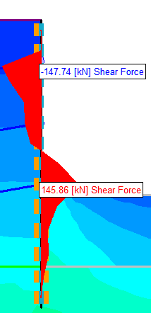
12 3 4

13 5

14 Question 1.8 Design the pile reinforcement against flexural, axial and shear failure. Assume a minimum concrete cover of 7.5cm and concrete class C30. For the design of the pile reinforcement against flexural and axial failure the pile is modelled as a cylindrical column and methods described in A.Topçu s textbook Reinforced Concrete (A.Topçu, 2015) and U.Ersoy s charts(ersoy, 1980) are used. On the other hand, design against shear failure is modelled by estimating the pile as a beam. Concrete & reinforcement specifications are; Concrete: C30/37 fcd=20mpa Reinforcement: B420C fyd=365.22mpa The chart used for the design, Figure 8 - Chart 8-62(ERSOY, 1980)

15 Flexural & Axial Failure Design Moment : kNm Design Axial Force : kN Area of Concrete = mm 4 2 d h Chart 8-62 is selected. Nd Af c cd M d A h f c cd m 0.28 Read from the Chart 8-62 f yd f 20 cd Ast mm Required reinforcement area Ast mm mm Checked Checked Φ24 Reinforcement is selected.
16 Shear Failure Design Shear Force = kN Design Axial Force = kN Area of Concrete = mm 4 2 Max. Shear Force = Vmax 0.22 f A kN cd c Critical Shear Force = ( 0.3) Nd Vcr 0.65 fctd Ac (1 ) kN A c V V V Shear demand can single-handedly fulfilled by concrete cross-section only. d cr max Therefore only minimum shear reinforcement is required.
17 Question 1.9 Estimate the factor of safety against base heave. In order to estimate the factor of safety against base heave, a simple method of analysing base stability developed by Bjerrum and Eide(Bjerrum and Eide, 1956) is used. For this method chart showed Figure 9 is used as the following; Figure 9 - Bearing Capacity Factors for Base Instability Analysis.(Bjerrum and Eide, 1956)
18 If we were to follow up on those formulations to the problem in hand, Where, Cu=100kPa γm=18.5kn/m3 H = 12m H/B = 0 H/L = 0 Then Ncv, from Figure 9 would be 5.2. Later, factor of safety could be calculated, F ( )
19 Question 1.10 Discuss if estimated lateral and vertical displacement profiles behind the pile wall is consistent with available literature. How would you improve the system if the displacements estimated are higher than allowable? If the displacements estimated are higher than allowable, the most effective way to improve displacements is to increase the pre-stress value of the anchorages. Additional anchorage installation or increase in pile diameter ( which will increase the rigidity of the wall ) would improve the displacements. References A.Topçu (2015) Reinforced Concrete. Bjerrum, L. and Eide, O. (1956) Stability of strutted excavations in clay., Geotechnique, 6(1), pp Clayton, C. R. I. (1986) Earth Pressure and Earth-Retaining Structures. Available at: ERSOY, U. (1980) Taşıma Gücü El Kitabı. Ankara. Ostermayer, H. (1970) Construction, carrying behaviour and creep characteristics of ground anchors, Ground Engineering, 33, p. 44.
Strengthening of Large Storage Tank Foundation Walls in an Aggressive Environment by External Post-tensioning. May 7th 2013: Dominique Deschamps
 Strengthening of Large Storage Tank Foundation Walls in an Aggressive Environment by External Post-tensioning May 7th 2013: Dominique Deschamps Scope of the paper Presentation of the project Cause of cracks
MECHANICS OF SOLIDS - BEAMS TUTORIAL 2 SHEAR FORCE AND BENDING MOMENTS IN BEAMS
 MECHANICS OF SOLIDS - BEAMS TUTORIAL 2 SHEAR FORCE AND BENDING MOMENTS IN BEAMS This is the second tutorial on bending of beams. You should judge your progress by completing the self assessment exercises.
Optimised Design for Soil Nailed Walls 1
 Optimised Design for Soil Nailed Walls 1 J A R Ortigao 1 and E M Palmeira 2 1 Federal University of Rio de Janeiro, Rio de Janeiro, Brazil 2 University of Brasília, Brasília, Brazil INTRODUCTION The first
Hardened Concrete. Lecture No. 14
 Hardened Concrete Lecture No. 14 Strength of Concrete Strength of concrete is commonly considered its most valuable property, although in many practical cases, other characteristics, such as durability
ENGINEERING SCIENCE H1 OUTCOME 1 - TUTORIAL 3 BENDING MOMENTS EDEXCEL HNC/D ENGINEERING SCIENCE LEVEL 4 H1 FORMERLY UNIT 21718P
 ENGINEERING SCIENCE H1 OUTCOME 1 - TUTORIAL 3 BENDING MOMENTS EDEXCEL HNC/D ENGINEERING SCIENCE LEVEL 4 H1 FORMERLY UNIT 21718P This material is duplicated in the Mechanical Principles module H2 and those
METHOD OF STATEMENT FOR STATIC LOADING TEST
 Compression Test, METHOD OF STATEMENT FOR STATIC LOADING TEST Tension Test and Lateral Test According to the American Standards ASTM D1143 07, ASTM D3689 07, ASTM D3966 07 and Euro Codes EC7 Table of Contents
Design of pile foundations following Eurocode 7-Section 7
 Brussels, 18-20 February 2008 Dissemination of information workshop 1 Workshop Eurocodes: background and applications Brussels, 18-20 Februray 2008 Design of pile foundations following Eurocode 7-Section
Module 7 (Lecture 24 to 28) RETAINING WALLS
 RETAINING WALLS") Module 7 (Lecture 24 to 28) RETAINING WALLS Topics 24.1 INTRODUCTION 24.2 GRAVITY AND CANTILEVER WALLS 24.3 PROPORTIONING RETAINING WALLS 24.4 APPLICATION OF LATERAL EARTH PRESSURE THEORIES TO DESIGN 24.5
Module 7 (Lecture 24 to 28) RETAINING WALLS Topics 24.1 INTRODUCTION 24.2 GRAVITY AND CANTILEVER WALLS 24.3 PROPORTIONING RETAINING WALLS 24.4 APPLICATION OF LATERAL EARTH PRESSURE THEORIES TO DESIGN 24.5
USE OF MICROPILES IN TEXAS BRIDGES. by John G. Delphia, P.E. TxDOT Bridge Division Geotechnical Branch
 USE OF MICROPILES IN TEXAS BRIDGES by John G. Delphia, P.E. TxDOT Bridge Division Geotechnical Branch DEFINITION OF A MICROPILE A micropile is a small diameter (typically less than 12 in.), drilled and
EXAMPLE 1 DESIGN OF CANTILEVERED WALL, GRANULAR SOIL
 EXAMPLE DESIGN OF CANTILEVERED WALL, GRANULAR SOIL A sheet pile wall is required to support a 2 excavation. The soil is uniform as shown in the figure. To take into account the friction between the wall
CEEN 162 - Geotechnical Engineering Laboratory Session 7 - Direct Shear and Unconfined Compression Tests
 PURPOSE: The parameters of the shear strength relationship provide a means of evaluating the load carrying capacity of soils, stability of slopes, and pile capacity. The direct shear test is one of the
REHABILITATION OF THE FIGUEIRA DA FOZ BRIDGE
 REHABILITATION OF THE FIGUEIRA DA FOZ BRIDGE A.Rito Proponte, Lda, Lisbon, Portugal J. Appleton A2P Consult, Lda, Lisbon, Portugal ABSTRACT: The Figueira da Foz Bridge includes a 405 m long cable stayed
System. Stability. Security. Integrity. 150 Helical Anchor
 Model 150 HELICAL ANCHOR System PN #MBHAT Stability. Security. Integrity. 150 Helical Anchor System About Foundation Supportworks is a network of the most experienced and knowledgeable foundation repair
Design Manual to BS8110
 Design Manual to BS8110 February 2010 195 195 195 280 280 195 195 195 195 195 195 280 280 195 195 195 The specialist team at LinkStudPSR Limited have created this comprehensive Design Manual, to assist
1997 Uniform Administrative Code Amendment for Earthen Material and Straw Bale Structures Tucson/Pima County, Arizona
 for Earthen Material and Straw Bale Structures SECTION 70 - GENERAL "APPENDIX CHAPTER 7 - EARTHEN MATERIAL STRUCTURES 70. Purpose. The purpose of this chapter is to establish minimum standards of safety
Design MEMO 60 Reinforcement design for TSS 102
 Date: 04.0.0 sss Page of 5 CONTENTS PART BASIC ASSUMTIONS... GENERAL... STANDARDS... QUALITIES... 3 DIMENSIONS... 3 LOADS... 3 PART REINFORCEMENT... 4 EQUILIBRIUM... 4 Date: 04.0.0 sss Page of 5 PART BASIC
Design MEMO 54a Reinforcement design for RVK 41
 Page of 5 CONTENTS PART BASIC ASSUMTIONS... 2 GENERAL... 2 STANDARDS... 2 QUALITIES... 3 DIMENSIONS... 3 LOADS... 3 PART 2 REINFORCEMENT... 4 EQUILIBRIUM... 4 Page 2 of 5 PART BASIC ASSUMTIONS GENERAL
Appendix A Sub surface displacements around excavations Data presented in Xdisp sample file
 Appendix A Sub surface displacements around excavations Data presented in Xdisp sample file Notation B1 = lowest level of basement slab c = cohesion E = drained Young s Modulus Eu = undrained Young s Modulus
Rehabilitation of Existing Foundation Building to Resist Lateral and Vertical Loads
 International Journal of Current Microbiology and Applied Sciences ISSN: 2319-7706 Volume 3 Number 12 (2014) pp. 950-961 http://www.ijcmas.com Original Research Article Rehabilitation of Existing Foundation
Validation of Cable Bolt Support Design in Weak Rock Using SMART Instruments and Phase 2
 Validation of Cable Bolt Support Design in Weak Rock Using SMART Instruments and Phase 2 W.F. Bawden, Chair Lassonde Mineral Engineering Program, U. of Toronto, Canada J.D. Tod, Senior Engineer, Mine Design
Supplier ID: 26421. Local Office: GLASGOW 69 Buchanan Street Glasgow G1 3HL
 M D & FOUNDATIONS MIDLANDS Supplier ID: 26421 MINI PILING PILING REINFORCED CONCRETE UNDERPINNING DRILLING & GROUTING SITE INVESTIGATION & PILE TESTING NATIONWIDE SPECIALIST PILING & FOUNDATION SERVICES
OPERE DI PROTEZIONE CONTRO LA CADUTA MASSI: ASPETTI PROGETTUALI. Reti in aderenza. Daniele PEILA. Daniele PEILA
 OPERE DI PROTEZIONE CONTRO LA CADUTA MASSI: ASPETTI PROGETTUALI Reti in aderenza 0 Simple mesh drapery system 1 Simple mesh drapery system 2 Fixed drapery sistem 3 Fixed drapery sistem 4 Fixed drapery
Local Authority Building Control Technical Information Note 3 Driven and In-situ Piled Foundations
 Local Authority Building Control Technical Information Note 3 Driven and In-situ Piled Foundations Cambridge City Council - East Cambridgeshire District Council - Fenland District Council, Huntingdonshire
Draft Table of Contents. Building Code Requirements for Structural Concrete and Commentary ACI 318-14
 Draft Table of Contents Building Code Requirements for Structural Concrete and Commentary ACI 318-14 BUILDING CODE REQUIREMENTS FOR STRUCTURAL CONCRETE (ACI 318 14) Chapter 1 General 1.1 Scope of ACI 318
Page 1 of 18 28.4.2008 Sven Alexander Last revised 1.3.2010. SB-Produksjon STATICAL CALCULATIONS FOR BCC 250
 Page 1 of 18 CONTENT PART 1 BASIC ASSUMPTIONS PAGE 1.1 General 1. Standards 1.3 Loads 1. Qualities PART ANCHORAGE OF THE UNITS.1 Beam unit equilibrium 3. Beam unit anchorage in front..1 Check of capacity..
Miss S. S. Nibhorkar 1 1 M. E (Structure) Scholar,
 Scholar,") Volume, Special Issue, ICSTSD Behaviour of Steel Bracing as a Global Retrofitting Technique Miss S. S. Nibhorkar M. E (Structure) Scholar, Civil Engineering Department, G. H. Raisoni College of Engineering
Volume, Special Issue, ICSTSD Behaviour of Steel Bracing as a Global Retrofitting Technique Miss S. S. Nibhorkar M. E (Structure) Scholar, Civil Engineering Department, G. H. Raisoni College of Engineering
SPECIFICATION FOR DYNAMIC CONSOLIDATION / DYNAMIC REPLACEMENT
 SPECIFICATION FOR DYNAMIC CONSOLIDATION / DYNAMIC REPLACEMENT 1.0 SOIL IMPROVEMENT 1.1 General Soil Investigation Information are provided in Part B1 annex as a guide to the Contractor for his consideration
MECHANICS OF SOLIDS - BEAMS TUTORIAL 1 STRESSES IN BEAMS DUE TO BENDING. On completion of this tutorial you should be able to do the following.
 MECHANICS OF SOLIDS - BEAMS TUTOIAL 1 STESSES IN BEAMS DUE TO BENDING This is the first tutorial on bending of beams designed for anyone wishing to study it at a fairly advanced level. You should judge
Underpinning Systems 14.1 FOUNDATION REPAIR. Helical Piles
 Helical Piles Howard A. Perko Copyright 0 2009 by John Wiley & Sons, Inc. All rights reserved. C h a p t e r 14 Underpinning Systems There has been tremendous growth in the use of helical piles for underpinning
REINFORCED CONCRETE. Reinforced Concrete Design. A Fundamental Approach - Fifth Edition. Walls are generally used to provide lateral support for:
 HANDOUT REINFORCED CONCRETE Reinforced Concrete Design A Fundamental Approach - Fifth Edition RETAINING WALLS Fifth Edition A. J. Clark School of Engineering Department of Civil and Environmental Engineering
FOUNDATION DESIGN. Instructional Materials Complementing FEMA 451, Design Examples
 FOUNDATION DESIGN Proportioning elements for: Transfer of seismic forces Strength and stiffness Shallow and deep foundations Elastic and plastic analysis Foundation Design 14-1 Load Path and Transfer to
NEGATIVE SKIN FRICTION AND SETTLEMENT OF PILES. Dr. Bengt H. Fellenius, P. Eng. University of Ottawa, Canada
 Fellenius, B. H., 1984. Negative skin friction and settlement of piles. Second International Seminar, Pile Foundations, Nanyang Technological Institute, Singapore, November 28-30, 12 p. NEGATIVE SKIN FRICTION
Numerical modelling of shear connection between concrete slab and sheeting deck
 7th fib International PhD Symposium in Civil Engineering 2008 September 10-13, Universität Stuttgart, Germany Numerical modelling of shear connection between concrete slab and sheeting deck Noémi Seres
Ground improvement using the vibro-stone column technique
 Ground improvement using the vibro-stone column technique A. Kosho 1 A.L.T.E.A & Geostudio 2000, Durres, Albania ABSTRACT The vibro stone columns technique is one of the most used techniques for ground
Pile test at the Shard London Bridge
 technical paper Pile test at the Shard London Bridge David Beadman, Byrne Looby Partners, Mark Pennington, Balfour Beatty Ground Engineering, Matthew Sharratt, WSP Group Introduction The Shard London Bridge,
Worked Example 2 (Version 1) Design of concrete cantilever retaining walls to resist earthquake loading for residential sites
 Design of concrete cantilever retaining walls to resist earthquake loading for residential sites") Worked Example 2 (Version 1) Design of concrete cantilever retaining walls to resist earthquake loading for residential sites Worked example to accompany MBIE Guidance on the seismic design of retaining
Worked Example 2 (Version 1) Design of concrete cantilever retaining walls to resist earthquake loading for residential sites Worked example to accompany MBIE Guidance on the seismic design of retaining
Design and Construction of Cantilevered Reinforced Concrete Structures
 Buildings Department Practice Note for Authorized Persons, Registered Structural Engineers and Registered Geotechnical Engineers APP-68 Design and Construction of Cantilevered Reinforced Concrete Structures
PILE FOUNDATIONS FM 5-134
 C H A P T E R 6 PILE FOUNDATIONS Section I. GROUP BEHAVIOR 6-1. Group action. Piles are most effective when combined in groups or clusters. Combining piles in a group complicates analysis since the characteristics
HUS-V Screw anchor. HUS-V Screw anchor. Basic loading data (for a single anchor) Mean ultimate resistance
 Mean ultimate resistance") HUS-V Screw anchor Anchor version HUS-V 8 / 10 Carbon steel concrete screw with hexagonal head Benefits - High productivity less drilling and fewer operations than with conventional anchors - Technical
HUS-V Screw anchor Anchor version HUS-V 8 / 10 Carbon steel concrete screw with hexagonal head Benefits - High productivity less drilling and fewer operations than with conventional anchors - Technical
Structural Design Criteria & Design Loads on Delhi Metro Rail and Checking of Safety of Radial Joints in Tunnel Lining Segments
 International Journal of Scientific and Research Publications, Volume 5, Issue 7, July 2015 1 Structural Design Criteria & Design Loads on Delhi Metro Rail and Checking of Safety of Radial Joints in Tunnel
EN 1997-1 Eurocode 7. Section 10 Hydraulic Failure Section 11 Overall Stability Section 12 Embankments. Trevor L.L. Orr Trinity College Dublin Ireland
 EN 1997 1: Sections 10, 11 and 12 Your logo Brussels, 18-20 February 2008 Dissemination of information workshop 1 EN 1997-1 Eurocode 7 Section 10 Hydraulic Failure Section 11 Overall Stability Section
Comprehensive Design Example 2: Foundations for Bulk Storage Facility
 Comprehensive Design Example 2: Foundations for Bulk Storage Facility Problem The project consists of building several dry product storage silos near an existing rail siding in an open field presently
HOW TO DESIGN CONCRETE STRUCTURES Foundations
 HOW TO DESIGN CONCRETE STRUCTURES Foundations Instructions for the Members of BIBM, CEMBUREAU, EFCA and ERMCO: It is the responsibility of the Members (national associations) of BIBM, CEMBUREAU, EFCA and
THE EFFECT OF STIRRUPS AND HOOKED STEEL FIBERS INSTEAD ON MOMENT-ROTATION CAPACITY OF BEAM-COLUMN CONNECTIONS
 THE EFFECT OF STIRRUPS AND HOOKED STEEL FIBERS INSTEAD ON MOMENT-ROTATION CAPACITY OF BEAM-COLUMN CONNECTIONS Assist. Prof. Dr. S. KamilAkın 1, Assist. Prof. Dr. Nail Kara 1, 1 Department of Civil Engineering,
Report on. Wind Resistance of Signs supported by. Glass Fiber Reinforced Concrete (GFRC) Pillars
 Pillars") Report on Wind Resistance of Signs supported by Glass Fiber Reinforced Concrete (GFRC) Pillars Prepared for US Sign and Fabrication Corporation January, 2006 SUMMARY This study found the attachment of
Report on Wind Resistance of Signs supported by Glass Fiber Reinforced Concrete (GFRC) Pillars Prepared for US Sign and Fabrication Corporation January, 2006 SUMMARY This study found the attachment of
Drained and Undrained Conditions. Undrained and Drained Shear Strength
 Drained and Undrained Conditions Undrained and Drained Shear Strength Lecture No. October, 00 Drained condition occurs when there is no change in pore water pressure due to external loading. In a drained
ALLOWABLE LOADS ON A SINGLE PILE
 C H A P T E R 5 ALLOWABLE LOADS ON A SINGLE PILE Section I. BASICS 5-1. Considerations. For safe, economical pile foundations in military construction, it is necessary to determine the allowable load capacity
Step 6 Buckling/Slenderness Considerations
 Step 6 Buckling/Slenderness Considerations Introduction Buckling of slender foundation elements is a common concern among designers and structural engineers. The literature shows that several researchers
CHAPTER 9 LONG TERM MONITORING AT THE ROUTE 351 BRIDGE
 CHAPTER 9 LONG TERM MONITORING AT THE ROUTE 351 BRIDGE 9.1 INTRODUCTION An important reason that composite piles have not gained wide acceptance in the civil engineering practice is the lack of a long
Designed and Engineered to Perform
 History EARTH CONTACT PRODUCTS, L.L.C., is a family owned company, based in Olathe, Kansas. This company was built upon Don May s U.S. Patented fourth-generation Steel Piering System that has led to the
Structural Analysis. EUROCODE 2 Background and Applications
 Dissemination of information for training Brussels, 20-21 October 2011 1 Prof. Dr.-Ing. Manfred Curbach TU Dresden, Institute for Concrete Structures M.Sc. Martin Just TU Dresden, Institute for Concrete
KWANG SING ENGINEERING PTE LTD
 KWANG SING ENGINEERING PTE LTD 1. INTRODUCTION This report represents the soil investigation works at Aljunied Road / Geylang East Central. The objective of the soil investigation is to obtain soil parameters
Technical Notes 3B - Brick Masonry Section Properties May 1993
 Technical Notes 3B - Brick Masonry Section Properties May 1993 Abstract: This Technical Notes is a design aid for the Building Code Requirements for Masonry Structures (ACI 530/ASCE 5/TMS 402-92) and Specifications
Earth Pressure and Retaining Wall Basics for Non-Geotechnical Engineers
 PDHonline Course C155 (2 PDH) Earth Pressure and Retaining Wall Basics for Non-Geotechnical Engineers Instructor: Richard P. Weber, P.E. 2012 PDH Online PDH Center 5272 Meadow Estates Drive Fairfax, VA
LOAD-CARRYING CAPACITY OF AXIALLY LOADED RODS GLUED-IN PERPENDICULAR TO THE GRAIN
 LOAD-CARRYING CAPACITY OF AXIALLY LOADED RODS GLUED-IN PERPENDICULAR TO TE GRAIN Prof. Dr.-Ing..J. Blaß, Dipl.-Ing. B. Laskewitz Universität Karlsruhe (T), Germany Abstract Glued-in rods have been used
Reliability of Estimated Anchor Pullout Resistance. Yasser A. Hegazy, M. ASCE 1
 Reliability of Estimated Anchor Pullout Resistance Yasser A. Hegazy, M. ASCE 1 Abstract In anchor pullout design, conservative soil and rock shear strength parameters are usually adopted. Presumptive values
Stresses in Beam (Basic Topics)
") Chapter 5 Stresses in Beam (Basic Topics) 5.1 Introduction Beam : loads acting transversely to the longitudinal axis the loads create shear forces and bending moments, stresses and strains due to V and
Chapter 5 Stresses in Beam (Basic Topics) 5.1 Introduction Beam : loads acting transversely to the longitudinal axis the loads create shear forces and bending moments, stresses and strains due to V and
PILE TESTING SPECIFICATION
 PILE TESTING SPECIFICATION 1.0 GENERAL This specification deals with the testing of a pile by the application of an axial load or force. It covers vertical and raking piles tested in compression (i.e.
Geotechnical Investigation Reports and Foundation Recommendations - Scope for Improvement - Examples
 Geotechnical Investigation Reports and Foundation Recommendations - Scope for Improvement - Examples Prof. V.S.Raju (Formerly: Director, IIT Delhi & Professor and Dean, IIT Madras) Email: [email protected]
Optimum proportions for the design of suspension bridge
 Journal of Civil Engineering (IEB), 34 (1) (26) 1-14 Optimum proportions for the design of suspension bridge Tanvir Manzur and Alamgir Habib Department of Civil Engineering Bangladesh University of Engineering
Program COLANY Stone Columns Settlement Analysis. User Manual
 User Manual 1 CONTENTS SYNOPSIS 3 1. INTRODUCTION 4 2. PROBLEM DEFINITION 4 2.1 Material Properties 2.2 Dimensions 2.3 Units 6 7 7 3. EXAMPLE PROBLEM 8 3.1 Description 3.2 Hand Calculation 8 8 4. COLANY
Seismic Analysis and Design of Steel Liquid Storage Tanks
 Vol. 1, 005 CSA Academic Perspective 0 Seismic Analysis and Design of Steel Liquid Storage Tanks Lisa Yunxia Wang California State Polytechnic University Pomona ABSTRACT Practicing engineers face many
Figure A-1. Figure A-2. continued on next page... HPM-1. Grout Reservoir. Neat Cement Grout (Very Flowable) Extension Displacement Plate
 Extension Displacement Plate") Addendum HELICAL PULLDOWN Micropile (HPM) Introduction The HPM is a system for constructing a grout column around the shaft of a standard Helical Screw Foundation (see Figure A1). To begin the process,
Addendum HELICAL PULLDOWN Micropile (HPM) Introduction The HPM is a system for constructing a grout column around the shaft of a standard Helical Screw Foundation (see Figure A1). To begin the process,
National Council of Examiners for Engineering and Surveying. Principles and Practice of Engineering Structural Examination
 Structural Effective Beginning with the April 2011 The structural engineering exam is a breadth and exam examination offered in two components on successive days. The 8-hour Vertical Forces (Gravity/Other)
PART TWO GEOSYNTHETIC SOIL REINFORCEMENT. Martin Street Improvements, Fredonia, Wisconsin; Keystone Compac Hewnstone
 GEOSYNTHETIC SOIL REINFORCEMENT Martin Street Improvements, Fredonia, Wisconsin; Keystone Compac Hewnstone DESIGN MANUAL & KEYWALL OPERATING GUIDE GEOSYNTHETIC SOIL REINFORCEMENT Keystone retaining walls
Optimising plate girder design
 Optimising plate girder design NSCC29 R. Abspoel 1 1 Division of structural engineering, Delft University of Technology, Delft, The Netherlands ABSTRACT: In the design of steel plate girders a high degree
SECTION 3 DESIGN OF POST TENSIONED COMPONENTS FOR FLEXURE
 SECTION 3 DESIGN OF POST TENSIONED COMPONENTS FOR FLEXURE DEVELOPED BY THE PTI EDC-130 EDUCATION COMMITTEE LEAD AUTHOR: TREY HAMILTON, UNIVERSITY OF FLORIDA NOTE: MOMENT DIAGRAM CONVENTION In PT design,
New construction Repairing failed or old foundations Retrofit foundations Permanent battered piers Machinery/equipment foundations
 from New construction foundations don t have to be a headache. The CHANCE Helical Pier Foundation System gives you the performance of concrete without the drawbacks and liabilities of driven piles and
EVALUATION OF SEISMIC RESPONSE - FACULTY OF LAND RECLAMATION AND ENVIRONMENTAL ENGINEERING -BUCHAREST
 EVALUATION OF SEISMIC RESPONSE - FACULTY OF LAND RECLAMATION AND ENVIRONMENTAL ENGINEERING -BUCHAREST Abstract Camelia SLAVE University of Agronomic Sciences and Veterinary Medicine of Bucharest, 59 Marasti
Embedded Retaining Wall Design Engineering or Paradox?
 Embedded Retaining Wall Design Engineering or Paradox? A personal viewpoint by A.Y. Chmoulian, associate at Royal Haskoning Introduction Retaining wall design theory is a complicated subject with a long
4B-2. 2. The stiffness of the floor and roof diaphragms. 3. The relative flexural and shear stiffness of the shear walls and of connections.
 Shear Walls Buildings that use shear walls as the lateral force-resisting system can be designed to provide a safe, serviceable, and economical solution for wind and earthquake resistance. Shear walls
Soil Screw Design Manual Edition 2
 Soil Screw Design Manual Edition 2 Page TOC-1 Hubbell Power Systems, Inc. All Rights Reserved Copyright 2015 CONTENTS CONTENTS TABLE of CONTENTS INTRODUCTION and APPLICATIONS Section 1 PURPOSE AND SCOPE...
Geotechnical Building Works (GBW) Submission Requirements
 Submission Requirements") Building Control (Amendment) Act 2012 and Regulations 2012: Geotechnical Building Works (GBW) Submission Requirements Building Engineering Group Building and Construction Authority May 2015 Content : 1.
Building Control (Amendment) Act 2012 and Regulations 2012: Geotechnical Building Works (GBW) Submission Requirements Building Engineering Group Building and Construction Authority May 2015 Content : 1.
SECTION 5 ANALYSIS OF CONTINUOUS SPANS DEVELOPED BY THE PTI EDC-130 EDUCATION COMMITTEE LEAD AUTHOR: BRYAN ALLRED
 SECTION 5 ANALYSIS OF CONTINUOUS SPANS DEVELOPED BY THE PTI EDC-130 EDUCATION COMMITTEE LEAD AUTHOR: BRYAN ALLRED NOTE: MOMENT DIAGRAM CONVENTION In PT design, it is preferable to draw moment diagrams
AP Physics C. Oscillations/SHM Review Packet
 AP Physics C Oscillations/SHM Review Packet 1. A 0.5 kg mass on a spring has a displacement as a function of time given by the equation x(t) = 0.8Cos(πt). Find the following: a. The time for one complete
DESIGN OF SLABS. 3) Based on support or boundary condition: Simply supported, Cantilever slab,
 Based on support or boundary condition: Simply supported, Cantilever slab,") DESIGN OF SLABS Dr. G. P. Chandradhara Professor of Civil Engineering S. J. College of Engineering Mysore 1. GENERAL A slab is a flat two dimensional planar structural element having thickness small compared
DESIGN OF SLABS Dr. G. P. Chandradhara Professor of Civil Engineering S. J. College of Engineering Mysore 1. GENERAL A slab is a flat two dimensional planar structural element having thickness small compared
Design of diaphragm and sheet pile walls. D-Sheet Piling. User Manual
 Design of diaphragm and sheet pile walls D-Sheet Piling User Manual D-SHEET PILING Design of diaphragm and sheet pile walls User Manual Version: 14.1.34974 31 July 2014 D-SHEET PILING, User Manual Published
CH. 2 LOADS ON BUILDINGS
 CH. 2 LOADS ON BUILDINGS GRAVITY LOADS Dead loads Vertical loads due to weight of building and any permanent equipment Dead loads of structural elements cannot be readily determined b/c weight depends
Instrumentations, Pile Group Load Testing, and Data Analysis Part II: Design & Analysis of Lateral Load Test. Murad Abu-Farsakh, Ph.D., P.E.
 Instrumentations, Pile Group Load Testing, and Data Analysis Part II: Design & Analysis of Lateral Load Test Murad Abu-Farsakh, Ph.D., P.E. Louisiana Transportation Research Center Louisiana State University
EDEXCEL NATIONAL CERTIFICATE/DIPLOMA MECHANICAL PRINCIPLES AND APPLICATIONS NQF LEVEL 3 OUTCOME 1 - LOADING SYSTEMS TUTORIAL 3 LOADED COMPONENTS
 EDEXCEL NATIONAL CERTIICATE/DIPLOMA MECHANICAL PRINCIPLES AND APPLICATIONS NQ LEVEL 3 OUTCOME 1 - LOADING SYSTEMS TUTORIAL 3 LOADED COMPONENTS 1. Be able to determine the effects of loading in static engineering
SECTION 3 DESIGN OF POST- TENSIONED COMPONENTS FOR FLEXURE
 SECTION 3 DESIGN OF POST- TENSIONED COMPONENTS FOR FLEXURE DEVELOPED BY THE PTI EDC-130 EDUCATION COMMITTEE LEAD AUTHOR: TREY HAMILTON, UNIVERSITY OF FLORIDA NOTE: MOMENT DIAGRAM CONVENTION In PT design,
STRESS AND DEFORMATION ANALYSIS OF LINEAR ELASTIC BARS IN TENSION
 Chapter 11 STRESS AND DEFORMATION ANALYSIS OF LINEAR ELASTIC BARS IN TENSION Figure 11.1: In Chapter10, the equilibrium, kinematic and constitutive equations for a general three-dimensional solid deformable
King Post Wall Information
 King Post Wall Information DAWSON-WAM specialise in the installation of piled retaining wall systems including steel sheet piling, concrete piled walls and king post walls. This document is our guide to
High Strain Dynamic Load Testing of Drilled Shafts
 Supplemental Technical Specification for High Strain Dynamic Load Testing of Drilled Shafts SCDOT Designation: SC-M-712 (9/15) September 3, 2015 1.0 GENERAL This work shall consist of performing high-strain
Section 5A: Guide to Designing with AAC
 Section 5A: Guide to Designing with AAC 5A.1 Introduction... 3 5A.3 Hebel Reinforced AAC Panels... 4 5A.4 Hebel AAC Panel Design Properties... 6 5A.5 Hebel AAC Floor and Roof Panel Spans... 6 5A.6 Deflection...
How to Design Helical Piles per the 2009 International Building Code
 ABSTRACT How to Design Helical Piles per the 2009 International Building Code by Darin Willis, P.E. 1 Helical piles and anchors have been used in construction applications for more than 150 years. The
Soil Strength. Performance Evaluation of Constructed Facilities Fall 2004. Prof. Mesut Pervizpour Office: KH #203 Ph: x4046
 ENGR-627 Performance Evaluation of Constructed Facilities, Lecture # 4 Performance Evaluation of Constructed Facilities Fall 2004 Prof. Mesut Pervizpour Office: KH #203 Ph: x4046 1 Soil Strength 2 Soil
Shear Forces and Bending Moments
 Chapter 4 Shear Forces and Bending Moments 4.1 Introduction Consider a beam subjected to transverse loads as shown in figure, the deflections occur in the plane same as the loading plane, is called the
PERFORMANCE TEST REPORT. Rendered to: FORMTECH ENTERPRISES, INC. SERIES/MODEL: Truline PRODUCT TYPE: PVC Seawall
 PERFORMANCE TEST REPORT Rendered to: FORMTECH ENTERPRISES, INC. SERIES/MODEL: Truline PRODUCT TYPE: PVC Seawall Report No.: Test Dates: 04/17/12 Through: 04/18/12 Report Date: 06/13/12 130 Derry Court
Module 5 (Lectures 17 to 19) MAT FOUNDATIONS
 MAT FOUNDATIONS") Module 5 (Lectures 17 to 19) MAT FOUNDATIONS Topics 17.1 INTRODUCTION Rectangular Combined Footing: Trapezoidal Combined Footings: Cantilever Footing: Mat foundation: 17.2 COMMON TYPES OF MAT FOUNDATIONS
Module 5 (Lectures 17 to 19) MAT FOUNDATIONS Topics 17.1 INTRODUCTION Rectangular Combined Footing: Trapezoidal Combined Footings: Cantilever Footing: Mat foundation: 17.2 COMMON TYPES OF MAT FOUNDATIONS
DESIGN OF PILES AND PILE GROUPS CONSIDERING CAPACITY, SETTLEMENT, AND NEGATIVE SKIN FRICTION
 DESIGN OF PILES AND PILE GROUPS CONSIDERING CAPACITY, SETTLEMENT, AND NEGATIVE SKIN FRICTION Introduction Bengt H. Fellenius, Dr.Tech., P.Eng. Background Notes for Demo Example for UniPile at www.unisoftltd.com
fischer Test Report Fixing Tests for Wienerberger Porotherm blocks
 fischer Test Report Fixing Tests for Wienerberger Porotherm blocks CONTENTS. Test Parameters... Substrates Tested Wienerberger Porotherm 90 &. Fixings Products Tested... Fischer Nylon UX Plug... Fischer
Basics of Reinforced Concrete Design
 Basics of Reinforced Concrete Design Presented by: Ronald Thornton, P.E. Define several terms related to reinforced concrete design Learn the basic theory behind structural analysis and reinforced concrete
Aluminium systems profile selection
 Aluminium systems profile selection The purpose of this document is to summarise the way that aluminium profile selection should be made, based on the strength requirements for each application. Curtain
APPENDIX A PRESSUREMETER TEST INTERPRETATION
 APPENDIX A PRESSUREMETER TEST INTERPRETATION PRESSUREMETER TEST INTERPRETATION Description of test The pressuremeter test, discussed in great detail by Martin (1977), Baguelin et al. (1978), Barksdale
Pro-Lift Steel Pile Foundation Repair
 Pro-Lift Steel Pile Foundation Repair Pro-Lift Steel Pile Foundation Repair System Pro-lift steel piles are designed for the stresses of Texas soils. They can have multiple steel walls, depending on the