SECTION 3 DESIGN OF POST TENSIONED COMPONENTS FOR FLEXURE
|
|
|
- Julius Wilkerson
- 10 years ago
- Views:
Transcription
1 SECTION 3 DESIGN OF POST TENSIONED COMPONENTS FOR FLEXURE DEVELOPED BY THE PTI EDC-130 EDUCATION COMMITTEE LEAD AUTHOR: TREY HAMILTON, UNIVERSITY OF FLORIDA

2 NOTE: MOMENT DIAGRAM CONVENTION In PT design, it is preferable to draw moment diagrams to the tensile face of the concrete section. The tensile face indicates what portion of the beam requires reinforcing for strength. When moment is drawn on the tension side, the diagram matches the general drape of the tendons. The tendons change their vertical location in the beam to follow the tensile moment diagram. Strands are at the top of the beam over the support and near the bottom at mid span. For convenience, the following slides contain moment diagrams drawn on both the tensile and compressive face, denoted by (T) and (C), in the lower left hand corner. Please delete the slides to suit the presenter's convention.

3 OBJECTIVE 1 hour presentation Flexure design considerations

4 PRESTRESSED GIRDER BEHAVIOR 1.2DL + 1.6LL k 1 DL DL Lin and Burns, Design of Prestressed Concrete Structures, 3 rd Ed., 1981

5 LIMIT STATES AND PRESENTATION Load Balancing k 1 DL OUTLINE Minimal deflection. Select k1 to balance majority of sustained load. Service DL + LL Concrete cracking. Check tension and compressive stresses. Strength 1.2DL + 1.6LL +1.0Secondary Ultimate strength. Check Design Flexural Strength ( M n )

6 EXAMPLE

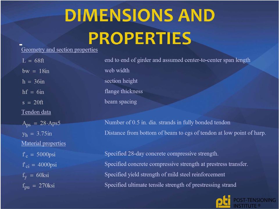
7 DIMENSIONS AND PROPERTIES
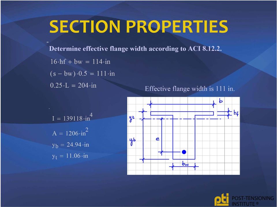
8 SECTION PROPERTIES
9 LOAD BALANCING Tendons apply external self equilibrating transverse loads to member. Forces applied through anchorages The angular change in tendon profile causes a transverse force on the member

10 LOAD BALANCING Transverse forces from tendon balances structural dead loads. Moments caused by the equivalent loads are equal to internal moments caused by prestressing force

11 EQUIVALENT LOAD Harped Tendon can be sized and placed such that the upward force exerted by the tendon at midspan exactly balances the applied concentrated load

12 EQUIVALENT LOAD Parabolic Tendon can be sized and placed such that the upward force exerted by the tendon along the length of the member exactly balances the applied uniformly distributed load

13 FORMULAS (FROM PTI DESIGN MANUAL?)
")
14 EXAMPLE LOAD BALANCING Determine portion of total dead load balanced by prestressing w DL = 0.20 klf superimposed dead load (10psf*20ft) w sw = 2.06 klf self weight including tributary width of slab

15 EXAMPLE LOAD BALANCING Including all short and long term losses

16 EXAMPLE LOAD BALANCING Prestressing in this example balances ~100% of total dead load. In general, balance 65 to 100% of the self weight Balancing in this range does not guarantee that service or strength limit states will be met. These must be checked separately

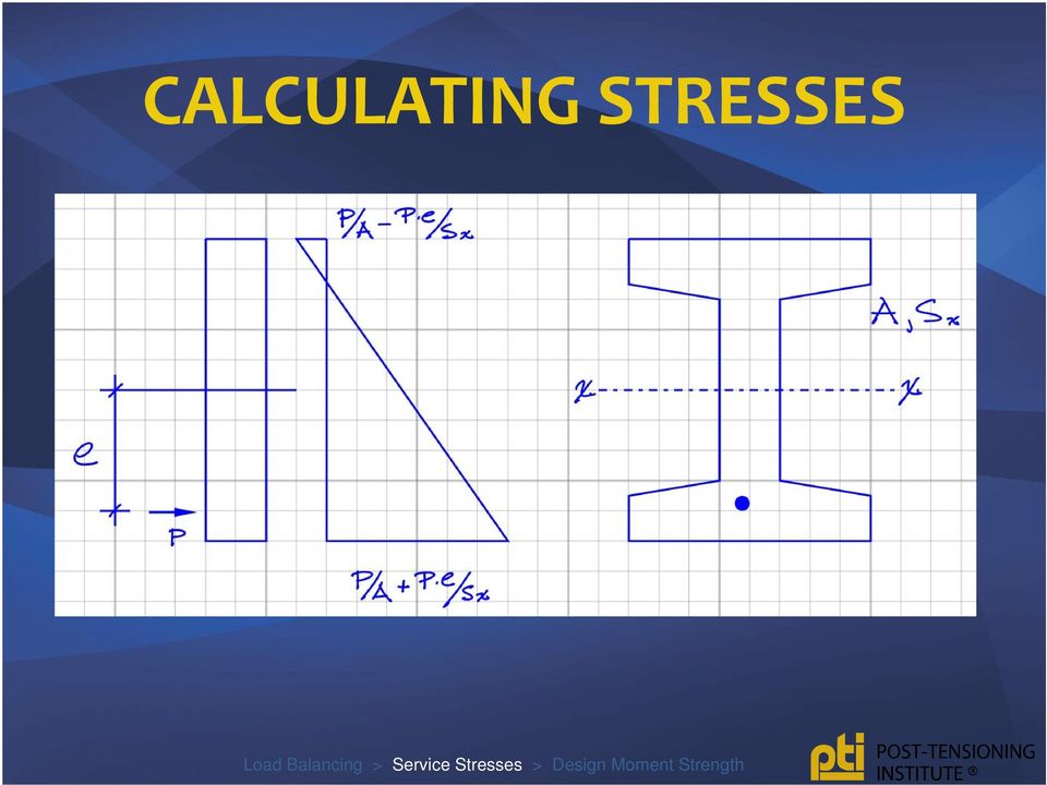
17 STRESSES Section remains uncracked Stress strain relationship is linear for both concrete and steel Use superposition to sum stress effect of each load. Prestressing is just another load.

18 CALCULATING STRESSES
19 STRESSES Stresses are typically checked at significant stages The number of stages varies with the complexity and type of prestressing. Stresses are usually calculated for the service level loads imposed (i.e. load factors are equal to 1.0). This includes the forces imposed by the prestressing.
. This includes the forces imposed by the prestressing.")
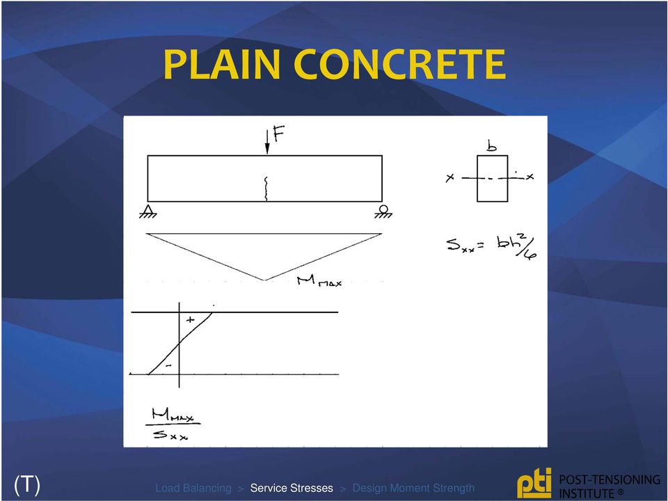
20 PLAIN CONCRETE (T)
21 PLAIN CONCRETE (C)
22 CONCENTRIC PRESTRESSING (T)
23 CONCENTRIC PRESTRESSING (C)
24 ECCENTRIC PRESTRESSING (T)
25 ECCENTRIC PRESTRESSING (C)
26 ECCENTRIC PRESTRESSING STRESSES AT SUPPORT (T)
27 ECCENTRIC PRESTRESSING STRESSES AT SUPPORT (C)
28 VARY TENDON ECCENTRICITY Harped Tendon follows moment diagram from concentrated load Parabolic Drape follows moment diagram from uniformly distributed load (T)
29 VARY TENDON ECCENTRICITY Harped Tendon follows moment diagram from concentrated load Parabolic Drape follows moment diagram from uniformly distributed load (C)
30 STRESSES AT TRANSFER MIDSPAN Including friction and elastic losses
31 STRESSES AT TRANSFER FULL LENGTH Stress in top fiber Stress in bottom fiber
32 STRESSES AT SERVICE MIDSPAN Including all short and long term losses
33 STRESSES AT SERVICE FULL LENGTH Stress in top fiber Stress in bottom fiber Transition (7.5 root f c) Cracked (12 root f c)
34 FLEXURAL STRENGTH (MN) ACI 318 indicates that the design moment strength of flexural members are to be computed by the strength design procedure used for reinforced concrete with f ps is substituted for f y
35 ASSUMPTIONS Concrete strain capacity = Tension concrete ignored Equivalent stress block for concrete compression Strain diagram linear Mild steel: elastic perfectly plastic Prestressing steel: strain compatibility, or empirical Perfect bond (for bonded tendons)
36 f ps STRESS IN PRESTRESSING STEEL AT NOMINAL FLEXURAL STRENGTH Empirical (bonded and unbonded tendons) Strain compatibility (bonded only)
37 EMPIRICAL BONDED TENDONS 270 ksi prestressing strand
38 EMPIRICAL BONDED TENDONS NO MILD STEEL
39 BONDED VS. UNBONDED SYSTEMS Steel-Concrete force transfer is uniform along the length Assume steel strain = concrete strain (i.e. strain compatibility) Cracks restrained locally by steel bonded to adjacent concrete
40 BONDED VS UNBONDED SYSTEMS Steel-Concrete force transfer occurs at anchor locations Strain compatibility cannot be assumed at all sections Cracks restrained globally by steel strain over the entire tendon length If sufficient mild reinforcement is not provided, large cracks are possible
41 SPAN TO DEPTH 35 OR LESS SPAN TO DEPTH > 35 Careful with units for f se (psi)
42 COMBINED PRESTRESSING AND MILD STEEL Assume mild steel stress = fy Both tension forces contribute to Mn
43 STRENGTH REDUCTION FACTOR Applied to nominal moment strength (M n ) to obtain design strength ( M n ) ranges from 0.6 to 0.9 Determined from strain in extreme tension steel (mild or prestressing) Section is defined as compression controlled, transition, or tension controlled
44 STRENGTH REDUCTION FACTOR
45 DETERMINE FLEXURAL STRENGTH Is effective prestress sufficient? Determine f ps Use equilibrium to determine: Depth of stress block a Nominal moment strength M n Determine depth of neutral axis and strain in outside layer of steel (et) Determine Compute M n
46 f ps OF BONDED TENDON
47 a and
48 M N BONDED TENDON
49 REINFORCEMENT LIMITS Members containing bonded tendons must have sufficient flexural strength to avoid abrupt failure that might be precipitated by cracking. Members with unbonded tendons are not required to satisfy this provision.
50 REINFORCEMENT LIMITS
51 f ps UNBONDED TENDON
52 M n UNBONDED TENDON
53 MIN. BONDED REINF. Members with unbonded tendons must have a minimum area of bonded reinf. Must be placed as close to the tension face (precompressed tensile zone) as possible. A s = A ct A ct area of section in tension
54 AS MINIMUM
55 M n UNBONDED TENDON INCORPORATE MILD STEEL
SECTION 3 DESIGN OF POST- TENSIONED COMPONENTS FOR FLEXURE
 SECTION 3 DESIGN OF POST- TENSIONED COMPONENTS FOR FLEXURE DEVELOPED BY THE PTI EDC-130 EDUCATION COMMITTEE LEAD AUTHOR: TREY HAMILTON, UNIVERSITY OF FLORIDA NOTE: MOMENT DIAGRAM CONVENTION In PT design,
SECTION 5 ANALYSIS OF CONTINUOUS SPANS DEVELOPED BY THE PTI EDC-130 EDUCATION COMMITTEE LEAD AUTHOR: BRYAN ALLRED
 SECTION 5 ANALYSIS OF CONTINUOUS SPANS DEVELOPED BY THE PTI EDC-130 EDUCATION COMMITTEE LEAD AUTHOR: BRYAN ALLRED NOTE: MOMENT DIAGRAM CONVENTION In PT design, it is preferable to draw moment diagrams
Two-Way Post-Tensioned Design
 Page 1 of 9 The following example illustrates the design methods presented in ACI 318-05 and IBC 2003. Unless otherwise noted, all referenced table, figure, and equation numbers are from these books. The
PRESTRESSED CONCRETE. Introduction REINFORCED CONCRETE CHAPTER SPRING 2004. Reinforced Concrete Design. Fifth Edition. By Dr. Ibrahim.
 CHAPTER REINFORCED CONCRETE Reinforced Concrete Design A Fundamental Approach - Fifth Edition Fifth Edition PRESTRESSED CONCRETE A. J. Clark School of Engineering Department of Civil and Environmental
A transverse strip of the deck is assumed to support the truck axle loads. Shear and fatigue of the reinforcement need not be investigated.
 Design Step 4 Design Step 4.1 DECK SLAB DESIGN In addition to designing the deck for dead and live loads at the strength limit state, the AASHTO-LRFD specifications require checking the deck for vehicular
Fundamentals of Post-Tensioned Concrete Design for Buildings
 Fundamentals of Post-Tensioned Concrete Design for Buildings Part One by John P. Miller www.suncam.com Copyright 2012 John P. Miller Page 1 of 49 Overview of This Course This is Part One of a three-part
16. Beam-and-Slab Design
 ENDP311 Structural Concrete Design 16. Beam-and-Slab Design Beam-and-Slab System How does the slab work? L- beams and T- beams Holding beam and slab together University of Western Australia School of Civil
Guidelines for the Design of Post-Tensioned Floors
 Guidelines for the Design of Post-Tensioned Floors BY BIJAN O. AALAMI AND JENNIFER D. JURGENS his article presents a set of guidelines intended to T assist designers in routine post-tensioning design,
Spon Press PRESTRESSED CONCRETE DESIGN EUROCODES. University of Glasgow. Department of Civil Engineering. Prabhakara Bhatt LONDON AND NEW YORK
 PRESTRESSED CONCRETE DESIGN TO EUROCODES Prabhakara Bhatt Department of Civil Engineering University of Glasgow Spon Press an imprint of Taytor & Francfe LONDON AND NEW YORK CONTENTS Preface xix Basic
The following sketches show the plans of the two cases of one-way slabs. The spanning direction in each case is shown by the double headed arrow.
 9.2 One-way Slabs This section covers the following topics. Introduction Analysis and Design 9.2.1 Introduction Slabs are an important structural component where prestressing is applied. With increase
Design of reinforced concrete columns. Type of columns. Failure of reinforced concrete columns. Short column. Long column
 Design of reinforced concrete columns Type of columns Failure of reinforced concrete columns Short column Column fails in concrete crushed and bursting. Outward pressure break horizontal ties and bend
Reinforced Concrete Design
 FALL 2013 C C Reinforced Concrete Design CIVL 4135 ii 1 Chapter 1. Introduction 1.1. Reading Assignment Chapter 1 Sections 1.1 through 1.8 of text. 1.2. Introduction In the design and analysis of reinforced
DESIGN OF SLABS. 3) Based on support or boundary condition: Simply supported, Cantilever slab,
 Based on support or boundary condition: Simply supported, Cantilever slab,") DESIGN OF SLABS Dr. G. P. Chandradhara Professor of Civil Engineering S. J. College of Engineering Mysore 1. GENERAL A slab is a flat two dimensional planar structural element having thickness small compared
DESIGN OF SLABS Dr. G. P. Chandradhara Professor of Civil Engineering S. J. College of Engineering Mysore 1. GENERAL A slab is a flat two dimensional planar structural element having thickness small compared
Chapter 8. Flexural Analysis of T-Beams
 Chapter 8. Flexural Analysis of T-s 8.1. Reading Assignments Text Chapter 3.7; ACI 318, Section 8.10. 8.2. Occurrence and Configuration of T-s Common construction type.- used in conjunction with either
Presentation Goals and Outline. Introduction to Post-Tensioning. The Precast Show 2014 NPCA 1. Post-Tensioning Institute.
 Presentation Goals and Outline Develop understanding for: PT Basics: Prestressed concrete; advantages; modern PT systems; encapsulation and durability Application Concepts: Facts vs. myths; shortening
Draft Table of Contents. Building Code Requirements for Structural Concrete and Commentary ACI 318-14
 Draft Table of Contents Building Code Requirements for Structural Concrete and Commentary ACI 318-14 BUILDING CODE REQUIREMENTS FOR STRUCTURAL CONCRETE (ACI 318 14) Chapter 1 General 1.1 Scope of ACI 318
Technical Notes 3B - Brick Masonry Section Properties May 1993
 Technical Notes 3B - Brick Masonry Section Properties May 1993 Abstract: This Technical Notes is a design aid for the Building Code Requirements for Masonry Structures (ACI 530/ASCE 5/TMS 402-92) and Specifications
1.2 Advantages and Types of Prestressing
 1.2 Advantages and Types of Prestressing This section covers the following topics. Definitions Advantages of Prestressing Limitations of Prestressing Types of Prestressing 1.2.1 Definitions The terms commonly
9.3 Two-way Slabs (Part I)
") 9.3 Two-way Slabs (Part I) This section covers the following topics. Introduction Analysis and Design Features in Modeling and Analysis Distribution of Moments to Strips 9.3.1 Introduction The slabs are
9.3 Two-way Slabs (Part I) This section covers the following topics. Introduction Analysis and Design Features in Modeling and Analysis Distribution of Moments to Strips 9.3.1 Introduction The slabs are
Type of Force 1 Axial (tension / compression) Shear. 3 Bending 4 Torsion 5 Images 6 Symbol (+ -)
 Shear. 3 Bending 4 Torsion 5 Images 6 Symbol (+ -)") Cause: external force P Force vs. Stress Effect: internal stress f 05 Force vs. Stress Copyright G G Schierle, 2001-05 press Esc to end, for next, for previous slide 1 Type of Force 1 Axial (tension /
Cause: external force P Force vs. Stress Effect: internal stress f 05 Force vs. Stress Copyright G G Schierle, 2001-05 press Esc to end, for next, for previous slide 1 Type of Force 1 Axial (tension /
INTRODUCTION TO BEAMS
 CHAPTER Structural Steel Design LRFD Method INTRODUCTION TO BEAMS Third Edition A. J. Clark School of Engineering Department of Civil and Environmental Engineering Part II Structural Steel Design and Analysis
MATERIALS AND MECHANICS OF BENDING
 HAPTER Reinforced oncrete Design Fifth Edition MATERIALS AND MEHANIS OF BENDING A. J. lark School of Engineering Department of ivil and Environmental Engineering Part I oncrete Design and Analysis b FALL
BRIDGE DESIGN SPECIFICATIONS APRIL 2000 SECTION 9 - PRESTRESSED CONCRETE
 SECTION 9 - PRESTRESSED CONCRETE Part A General Requirements and Materials 9.1 APPLICATION 9.1.1 General The specifications of this section are intended for design of prestressed concrete bridge members.
Chapter - 3 Design of Rectangular Beams and One-way Slabs
 Rectangular Beams and One-way Slabs Page 1 of 9 Chapter - 3 Design of Rectangular Beams and One-way Slabs 12 h A 12 strip in a simply supported one-way slab h b=12 L Rectangular Beams and One-way Slabs
APPENDIX C Slab Calculation 2
 APPENDIX C Slab Calculation 2 Now try calculating the same slab, with the minimum recommended balanced load of 50% of self-weight. (As opposed to 50% of DL LL used in the first calculation). The same thickness
Section 5A: Guide to Designing with AAC
 Section 5A: Guide to Designing with AAC 5A.1 Introduction... 3 5A.3 Hebel Reinforced AAC Panels... 4 5A.4 Hebel AAC Panel Design Properties... 6 5A.5 Hebel AAC Floor and Roof Panel Spans... 6 5A.6 Deflection...
Chapter 5 Bridge Deck Slabs. Bridge Engineering 1
 Chapter 5 Bridge Deck Slabs Bridge Engineering 1 Basic types of bridge decks In-situ reinforced concrete deck- (most common type) Pre-cast concrete deck (minimize the use of local labor) Open steel grid
ABSTRACT 1. INTRODUCTION 2. DESCRIPTION OF THE SEGMENTAL BEAM
 Ninth LACCEI Latin American and Caribbean Conference (LACCEI 11), Engineering for a Smart Planet, Innovation, Information Technology and Computational Tools for Sustainable Development, August 3-, 11,
ENGINEERING SCIENCE H1 OUTCOME 1 - TUTORIAL 3 BENDING MOMENTS EDEXCEL HNC/D ENGINEERING SCIENCE LEVEL 4 H1 FORMERLY UNIT 21718P
 ENGINEERING SCIENCE H1 OUTCOME 1 - TUTORIAL 3 BENDING MOMENTS EDEXCEL HNC/D ENGINEERING SCIENCE LEVEL 4 H1 FORMERLY UNIT 21718P This material is duplicated in the Mechanical Principles module H2 and those
LOAD TESTING FOR BRIDGE RATING: DEAN S MILL OVER HANNACROIS CREEK
 REPORT FHWA/NY/SR-06/147 LOAD TESTING FOR BRIDGE RATING: DEAN S MILL OVER HANNACROIS CREEK OSMAN HAG-ELSAFI JONATHAN KUNIN SPECIAL REPORT 147 TRANSPORTATION RESEARCH AND DEVELOPMENT BUREAU New York State
MECHANICS OF SOLIDS - BEAMS TUTORIAL 2 SHEAR FORCE AND BENDING MOMENTS IN BEAMS
 MECHANICS OF SOLIDS - BEAMS TUTORIAL 2 SHEAR FORCE AND BENDING MOMENTS IN BEAMS This is the second tutorial on bending of beams. You should judge your progress by completing the self assessment exercises.
Reinforced Concrete Design Project Five Story Office Building
 Reinforced Concrete Design Project Five Story Office Building Andrew Bartolini December 7, 2012 Designer 1 Partner: Shannon Warchol CE 40270: Reinforced Concrete Design Bartolini 2 Table of Contents Abstract...3
SLAB DESIGN. Introduction ACI318 Code provides two design procedures for slab systems:
 Reading Assignment SLAB DESIGN Chapter 9 of Text and, Chapter 13 of ACI318-02 Introduction ACI318 Code provides two design procedures for slab systems: 13.6.1 Direct Design Method (DDM) For slab systems
MECHANICS OF SOLIDS - BEAMS TUTORIAL 1 STRESSES IN BEAMS DUE TO BENDING. On completion of this tutorial you should be able to do the following.
 MECHANICS OF SOLIDS - BEAMS TUTOIAL 1 STESSES IN BEAMS DUE TO BENDING This is the first tutorial on bending of beams designed for anyone wishing to study it at a fairly advanced level. You should judge
SEISMIC UPGRADE OF OAK STREET BRIDGE WITH GFRP
 13 th World Conference on Earthquake Engineering Vancouver, B.C., Canada August 1-6, 2004 Paper No. 3279 SEISMIC UPGRADE OF OAK STREET BRIDGE WITH GFRP Yuming DING 1, Bruce HAMERSLEY 2 SUMMARY Vancouver
Post-Tensioned Concrete in Buildings
 Post-Tensioned Concrete in Buildings A 40+ Year Overview By Ken Bondy ACI Fall Convention San Francisco, October 2004 41 Years Ago It was the fall of 1963 I was 23 years old I had completed my MSCE course
Design of prestressed Concrete flat slabs
 Report No. 2 Design of prestressed Concrete flat slabs Joint Structural Division of the South African Institution of Civil Engineering and the Institution of Structural Engineers ISBN 0-620 - 17667-9 The
DESIGN OF SLABS. Department of Structures and Materials Engineering Faculty of Civil and Environmental Engineering University Tun Hussein Onn Malaysia
 DESIGN OF SLABS Department of Structures and Materials Engineering Faculty of Civil and Environmental Engineering University Tun Hussein Onn Malaysia Introduction Types of Slab Slabs are plate elements
Flexural Strength of Reinforced and Prestressed Concrete T-Beams
 Flexural Strength of Reinforced and Prestressed Concrete T-Beams Richard Brice, P.E. Bridge Software Engineer Bridge & Structures Office Washington State Department of Transportation Olympia, Washington
Statics of Structural Supports
 Statics of Structural Supports TYPES OF FORCES External Forces actions of other bodies on the structure under consideration. Internal Forces forces and couples exerted on a member or portion of the structure
Detailing of Reinforcement in Concrete Structures
 THE CIVIL & STRUCTURAL ENGINEERING PANEL ENGINEERS AUSTRALIA SYDNEY DIVISION 28 August 2012 Detailing of Reinforcement in Concrete Structures R.I. Gilbert Introduction: Detailing is often considered to
Basics of Reinforced Concrete Design
 Basics of Reinforced Concrete Design Presented by: Ronald Thornton, P.E. Define several terms related to reinforced concrete design Learn the basic theory behind structural analysis and reinforced concrete
Prestressed Concrete I-Beam and TxGirder Haunch Design Guide
 Prestressed Concrete I-Beam and TxGirder Haunch Design Guide Components of the Haunch Camber: Camber is the upward deflection in the beam after release of the prestressing strands due to the eccentricity
Structural Axial, Shear and Bending Moments
 Structural Axial, Shear and Bending Moments Positive Internal Forces Acting Recall from mechanics of materials that the internal forces P (generic axial), V (shear) and M (moment) represent resultants
Concrete Design Manual
 The Reinforced Concrete Design Manual In Accordance with ACI 318-11 SP-17(11) Vol 2 ACI SP-17(11) Volume 2 THE REINFORCED CONCRETE DESIGN MANUAL in Accordance with ACI 318-11 Anchoring to concrete Publication:
Deflection Calculation of RC Beams: Finite Element Software Versus Design Code Methods
 Deflection Calculation of RC Beams: Finite Element Software Versus Design Code Methods G. Kaklauskas, Vilnius Gediminas Technical University, 1223 Vilnius, Lithuania ([email protected]) V.
General Approach. Structure Components. Is all lumber the same? Lumber Grades. Rafters Girders / Beams Columns. Sketch general structural layout
 General Approach Sketch general structural layout Determine roof loading Determine required lumber dimensions Transfer load down the structure Structure Components Plants Structure Components Top Side
METHOD OF STATEMENT FOR STATIC LOADING TEST
 Compression Test, METHOD OF STATEMENT FOR STATIC LOADING TEST Tension Test and Lateral Test According to the American Standards ASTM D1143 07, ASTM D3689 07, ASTM D3966 07 and Euro Codes EC7 Table of Contents
SLAB DESIGN EXAMPLE. Deck Design (AASHTO LRFD 9.7.1) TYPICAL SECTION. County: Any Hwy: Any Design: BRG Date: 7/2010
 TYPICAL SECTION. County: Any Hwy: Any Design: BRG Date: 7/2010") County: Any Hwy: Any Design: BRG Date: 7/2010 SLAB DESIGN EXAMPLE Design example is in accordance with the AASHTO LRFD Bridge Design Specifications, 5th Ed. (2010) as prescribed by TxDOT Bridge Design
County: Any Hwy: Any Design: BRG Date: 7/2010 SLAB DESIGN EXAMPLE Design example is in accordance with the AASHTO LRFD Bridge Design Specifications, 5th Ed. (2010) as prescribed by TxDOT Bridge Design
Detailing of Reinforcment in Concrete Structures
 Chapter 8 Detailing of Reinforcment in Concrete Structures 8.1 Scope Provisions of Sec. 8.1 and 8.2 of Chapter 8 shall apply for detailing of reinforcement in reinforced concrete members, in general. For
Optimising plate girder design
 Optimising plate girder design NSCC29 R. Abspoel 1 1 Division of structural engineering, Delft University of Technology, Delft, The Netherlands ABSTRACT: In the design of steel plate girders a high degree
Stresses in Beam (Basic Topics)
") Chapter 5 Stresses in Beam (Basic Topics) 5.1 Introduction Beam : loads acting transversely to the longitudinal axis the loads create shear forces and bending moments, stresses and strains due to V and
Chapter 5 Stresses in Beam (Basic Topics) 5.1 Introduction Beam : loads acting transversely to the longitudinal axis the loads create shear forces and bending moments, stresses and strains due to V and
PCI BIG BEAM COMPETITION
 PCI BIG BEAM COMPETITION Official Rules for the PCI Engineering Design Competition Academic Year 2015-16 PROGRAM The PCI Student Education Committee is inviting entries from students to participate in
Session 5D: Benefits of Live Load Testing and Finite Element Modeling in Rating Bridges
 Session 5D: Benefits of Live Load Testing and Finite Element Modeling in Rating Bridges Douglas R. Heath P.E., Structural Engineer Corey Richard P.E., Project Manager AECOM Overview Bridge Testing/Rating
Figure A. Maximum load testing of new precast concrete floor plank system
 Load Testing of Precast Concrete Plank By Peter Gorgas, E.I.T. Figure A. Maximum load testing of new precast concrete floor plank system Overview Testing was performed in July 2012 at Northeast Precast
How To Make A Steel Beam
 Resistenza a taglio di travi in calcestruzzo fibrorinforzato Università degli Studi di Brescia [email protected] Milano June 17 th, 2015 Outlines Shear Action Factor affecting the shear strength
Guide to the Concrete Capacity Design (CCD) Method Embedment Design Examples
 Method Embedment Design Examples") ACI 349.2R-07 Guide to the Concrete Capacity Design (CCD) Method Embedment Design Examples Reported by ACI Committee 349 Ronald J. Janowiak Chair Omesh B. Abhat Werner Fuchs Christopher Heinz * Richard
ACI 349.2R-07 Guide to the Concrete Capacity Design (CCD) Method Embedment Design Examples Reported by ACI Committee 349 Ronald J. Janowiak Chair Omesh B. Abhat Werner Fuchs Christopher Heinz * Richard
Requirements for the Use of PRESSS Moment-Resisting Frame Systems
 Requirements for the Use of PRESSS Moment-Resisting Frame Systems Neil M. Hawkins, Ph.D. Professor Emeritus Department of Civil Engineering University of Illinois at Urbana-Champaign Urbana, Illinois S.
The Impact of Market Demands on Residential Post-Tensioned Foundation Design: An Ethical Dilemma
 The Impact of Market Demands on Residential Post-Tensioned Foundation Design: An Ethical Dilemma Bart B. Barrett, B.S., P.E.1 Kerry S. Lee, M.B.A., P.E., M. ASCE2 Erik L. Nelson, Ph.D., P.E., M. ASCE3
Deflections. Question: What are Structural Deflections?
 Question: What are Structural Deflections? Answer: The deformations or movements of a structure and its components, such as beams and trusses, from their original positions. It is as important for the
FOUNDATION DESIGN. Instructional Materials Complementing FEMA 451, Design Examples
 FOUNDATION DESIGN Proportioning elements for: Transfer of seismic forces Strength and stiffness Shallow and deep foundations Elastic and plastic analysis Foundation Design 14-1 Load Path and Transfer to
Structural Integrity Analysis
 Structural Integrity Analysis 1. STRESS CONCENTRATION Igor Kokcharov 1.1 STRESSES AND CONCENTRATORS 1.1.1 Stress An applied external force F causes inner forces in the carrying structure. Inner forces
SEISMIC DESIGN. Various building codes consider the following categories for the analysis and design for earthquake loading:
 SEISMIC DESIGN Various building codes consider the following categories for the analysis and design for earthquake loading: 1. Seismic Performance Category (SPC), varies from A to E, depending on how the
Strengthening of Large Storage Tank Foundation Walls in an Aggressive Environment by External Post-tensioning. May 7th 2013: Dominique Deschamps
 Strengthening of Large Storage Tank Foundation Walls in an Aggressive Environment by External Post-tensioning May 7th 2013: Dominique Deschamps Scope of the paper Presentation of the project Cause of cracks
ETABS. Integrated Building Design Software. Concrete Frame Design Manual. Computers and Structures, Inc. Berkeley, California, USA
 ETABS Integrated Building Design Software Concrete Frame Design Manual Computers and Structures, Inc. Berkeley, California, USA Version 8 January 2002 Copyright The computer program ETABS and all associated
In-situ Load Testing to Evaluate New Repair Techniques
 In-situ Load Testing to Evaluate New Repair Techniques W.J. Gold 1 and A. Nanni 2 1 Assistant Research Engineer, Univ. of Missouri Rolla, Dept. of Civil Engineering 2 V&M Jones Professor, Univ. of Missouri
RC Detailing to Eurocode 2
 RC Detailing to Eurocode 2 Jenny Burridge MA CEng MICE MIStructE Head of Structural Engineering Structural Eurocodes BS EN 1990 (EC0): BS EN 1991 (EC1): Basis of structural design Actions on Structures
Lecture Note 17 PRESTRESS CONCRETE
 8 ecture Note 17 RESTRESS CONCRETE Code: IS1343: 1980 Introduction: Definition of restress: restress is defined as a method of applying pre-compression to control the stresses resulting due to external
[TECHNICAL REPORT I:]
![[TECHNICAL REPORT I:]](/thumbs/26/8259375.jpg "[TECHNICAL REPORT I:]") [Helios Plaza] Houston, Texas Structural Option Adviser: Dr. Linda Hanagan [TECHNICAL REPORT I:] Structural Concepts & Existing Conditions Table of Contents Executive Summary... 2 Introduction... 3 Structural
[Helios Plaza] Houston, Texas Structural Option Adviser: Dr. Linda Hanagan [TECHNICAL REPORT I:] Structural Concepts & Existing Conditions Table of Contents Executive Summary... 2 Introduction... 3 Structural
REINFORCED CONCRETE. Reinforced Concrete Design. A Fundamental Approach - Fifth Edition. Walls are generally used to provide lateral support for:
 HANDOUT REINFORCED CONCRETE Reinforced Concrete Design A Fundamental Approach - Fifth Edition RETAINING WALLS Fifth Edition A. J. Clark School of Engineering Department of Civil and Environmental Engineering
1997 Uniform Administrative Code Amendment for Earthen Material and Straw Bale Structures Tucson/Pima County, Arizona
 for Earthen Material and Straw Bale Structures SECTION 70 - GENERAL "APPENDIX CHAPTER 7 - EARTHEN MATERIAL STRUCTURES 70. Purpose. The purpose of this chapter is to establish minimum standards of safety
Chapter 2 Basis of design and materials
 Chapter 2 Basis of design and materials 2.1 Structural action It is necessary to start a design by deciding on the type and layout of structure to be used. Tentative sizes must be allocated to each structural
Numerical modelling of shear connection between concrete slab and sheeting deck
 7th fib International PhD Symposium in Civil Engineering 2008 September 10-13, Universität Stuttgart, Germany Numerical modelling of shear connection between concrete slab and sheeting deck Noémi Seres
APE T CFRP Aslan 500
 Carbon Fiber Reinforced Polymer (CFRP) Tape is used for structural strengthening of concrete, masonry or timber elements using the technique known as Near Surface Mount or NSM strengthening. Use of CFRP
Steel and composite bridges in Germany State of the Art
 Steel and composite bridges in Germany State of the Art Univ.-Prof. Dr.-Ing. G. Hanswille Institute for Steel and Composite Structures University of Wuppertal Germany Univ.-Prof. em. Dr.-Ing. Dr. h.c.
Bridging Your Innovations to Realities
 Graphic User Interface Graphic User Interface Modeling Features Bridge Applications Segmental Bridges Cable Bridges Analysis Features Result Evaluation Design Features 02 07 13 17 28 34 43 48 2 User Interface
TECHNICAL SPECIFICATION SERIES 8000 PRECAST CONCRETE
 TECHNICAL SPECIFICATION SERIES 8000 PRECAST CONCRETE TECHNICAL SPECIFICATION PART 8000 - PRECAST CONCRETE TABLE OF CONTENTS Item Number Page 8100 PRECAST CONCRETE CONSTRUCTION - GENERAL 8-3 8101 General
FUTURE SLAB. PENETRATIONS and. DEMOLITION of POST-TENSIONED FLOORS
 FUTURE SLAB PENETRATIONS and DEMOLITION of POST-TENSIONED FLOORS 1.0 INTRODUCTION Post-tensioned floor slabs in Australia and South East Asia are now universally regarded as the most cost effective form
STRUSOFT EXAMPLES PRE-STRESS 6.4
 EXAMPLES PRE-STRESS 6.4 STEP BY STEP EXAMPLES 6.o4.oo5-2o14-o7-o18 Page 1 CONTENTS 1 BASIC CONCEPT 2 1.1 CODES 2 1.2 LAYOUT OF THE PROGRAM 3 1.3 LIMITATIONS IN THE CURRENT VERSION 3 2 EXAMPLES 4 2.1 MODELLING
National Council of Examiners for Engineering and Surveying. Principles and Practice of Engineering Structural Examination
 Structural Effective Beginning with the April 2011 The structural engineering exam is a breadth and exam examination offered in two components on successive days. The 8-hour Vertical Forces (Gravity/Other)
S03: Tier 1 Assessment of Shear in Concrete Short Span Bridges to AS 5100 and AS 3600
 Annexure S03: Tier 1 Assessment of Shear in Concrete Short Span Bridges to AS 5100 and AS 3600 April 2014 Copyright http://creativecommons.org/licenses/by/3.0/au/ State of Queensland (Department of Transport
A Case Study Comparing Two Approaches for Applying Area Loads: Tributary Area Loads vs Shell Pressure Loads
 1 A Case Study Comparing Two Approaches for Applying Area Loads: Tributary Area Loads vs Shell Pressure Loads By Dr. Siriwut Sasibut (Application Engineer) S-FRAME Software Inc. #1158 13351 Commerce Parkway
Composite Floor System
 Composite Floor System INTRODUCTION This manual has been developed in order to assist you in understanding the Hambro Composite Floor System, and for you to have at your fingertips the information necessary
Fire and Concrete Structures
 Fire and Concrete Structures Authors: David N. Bilow, P.E., S.E., Director, Engineered Structures, Portland Cement Association 5420 Old Orchard Road, Skokie, IL 60077,Phone 847-972-9064, email: [email protected]
EFFECTS ON NUMBER OF CABLES FOR MODAL ANALYSIS OF CABLE-STAYED BRIDGES
 EFFECTS ON NUMBER OF CABLES FOR MODAL ANALYSIS OF CABLE-STAYED BRIDGES Yang-Cheng Wang Associate Professor & Chairman Department of Civil Engineering Chinese Military Academy Feng-Shan 83000,Taiwan Republic
Analysis and Repair of an Earthquake-Damaged High-rise Building in Santiago, Chile
 Analysis and Repair of an Earthquake-Damaged High-rise Building in Santiago, Chile J. Sherstobitoff Ausenco Sandwell, Vancouver, Canada P. Cajiao AMEC, Vancouver, Canada P. Adebar University of British
STRUCTURAL WELDED WIRE REINFORCEMENT
 STRUCTURAL WELDED WIRE REINFORCEMENT 2 1 WIRE REINFORCEMENT INSTITUTE, INC. Excellence Set in Concrete www.wirereinforcementinstitute.org Manual of Standard Practice Structural Welded Wire Reinforcement
Long-term serviceability of the structure Minimal maintenance requirements Economical construction Improved aesthetics and safety considerations
 Design Step 7.1 INTEGRAL ABUTMENT DESIGN General considerations and common practices Integral abutments are used to eliminate expansion joints at the end of a bridge. They often result in Jointless Bridges
Bending Stress in Beams
 936-73-600 Bending Stress in Beams Derive a relationship for bending stress in a beam: Basic Assumptions:. Deflections are very small with respect to the depth of the beam. Plane sections before bending
FINITE ELEMENT ANALYSIS OF DEEP WIDE-FLANGED PRE-STRESSED GIRDERS TO UNDERSTAND AND CONTROL END CRACKING
 Wisconsin Highway Research Program FINITE ELEMENT ANALYSIS OF DEEP WIDE-FLANGED PRE-STRESSED GIRDERS TO UNDERSTAND AND CONTROL END CRACKING SPR # 0092-10-12 Michael G. Oliva, Ph.D Pinar Okumus, Ph.D. Candidate
Field Damage Inspection and Static Load Test Analysis of Jiamusi Highway Prestressed Concrete Bridge in China
 Advanced Materials Research Vols. 163-167 (2011) pp 1147-1156 Online available since 2010/Dec/06 at www.scientific.net (2011) Trans Tech Publications, Switzerland doi:10.4028/www.scientific.net/amr.163-167.1147
Eurocode 2: Design of concrete structures
 Eurocode 2: Design of concrete structures Owen Brooker, The Concrete Centre Introduction The transition to using the Eurocodes is a daunting prospect for engineers, but this needn t be the case. Industry
REPAIR AND STRENGTHENING OF HISTORICAL CONCRETE BRIDGE OVER VENTA RIVER IN LATVIA
 1 REPAIR AND STRENGTHENING OF HISTORICAL CONCRETE BRIDGE OVER VENTA RIVER IN LATVIA Verners Straupe, M.sc.eng., Rudolfs Gruberts, dipl. eng. JS Celuprojekts, Murjanu St. 7a, Riga, LV 1024, Latvia e-mail:
Behavior of High-Strength Concrete Rectangular Columns
 Seventh International Congress on Advances in Civil Engineering, October11-13, 26 Yildiz TechnicalUniversity, Istanbul, Turkey Behavior of High-Strength Concrete Rectangular Columns S. Kim, H. C. Mertol,
Optimum proportions for the design of suspension bridge
 Journal of Civil Engineering (IEB), 34 (1) (26) 1-14 Optimum proportions for the design of suspension bridge Tanvir Manzur and Alamgir Habib Department of Civil Engineering Bangladesh University of Engineering