Worked Example 2 (Version 1) Design of concrete cantilever retaining walls to resist earthquake loading for residential sites
|
|
|
- Marshall Arnold
- 8 years ago
- Views:
Transcription
1 Worked Example 2 (Version 1) Design of concrete cantilever retaining walls to resist earthquake loading for residential sites Worked example to accompany MBIE Guidance on the seismic design of retaining structures for residential sites in Greater Christchurch (Version 2) November 2014 Introduction Cantilever concrete retaining walls are commonly used for residential purposes, often as integral basement walls. Usually the cantilever wall stem is of concrete block construction rising from an in-situ concrete foundation. The following worked example is for a free-standing cantilever wall that is considered sufficiently flexible for active soil pressures to be used for design. Where used as integral basement walls they are often buttressed by return walls and floor diaphragms which may make them too stiff for active soil pressures to develop requiring higher design loads and a different design approach. 1.1 Possible modes of failure Possible modes of failure for free-standing concrete cantilever retaining walls are illustrated in cartoon fashion in Figure X.1. A complete design should address each of these modes of failure where appropriate. a) Wall stem structural failure: The wall stem fails in bending. Most likely location is at the base of the wall where the stem connects to the foundation. b) Foundation bearing failure: A bearing failure of the soil under the toe of the foundation and a forwards rotation of the wall. c) Sliding failure of wall: Possible mode for non-cohesive soils. Wall moves outwards with passive failure of soil in front of foundation and active failure of soil behind wall. Often a key is required beneath the foundation to prevent sliding. d) Deep seated rotational failure: Possible mode for cohesive soils. Factor of safety controlled by increasing length of heel or depth of key. Factor of safety calculated using limiting equilibrium Bishop analysis or similar. Unlikely to govern design unless wall is embedded into sloping ground with sloping backfill or there is a weak layer at the toe of the wall. 1

2 Figure X.1. Possible modes of failure for free-standing concrete cantilever retaining walls. The following worked example uses a simplified LRFD design procedure with load and resistance factors taken from B1/VM4. It is considered suitable for common residential situations with competent soils. This procedure is intended to be readily calculated by hand, although use of calculation software such as Mathcad or Excel will be useful for design iterations. The example calculations are made here using Mathcad. 1.2 Example Wall Figure X.2. Concrete cantilever wall example. The example wall is shown in Figure X.2. The wall is assumed to be located in the Christchurch Port Hills. The following design assumptions were made: Soil type: Strength parameters: Port Hills loess c = 0, φ = 30 degrees Drained strength parameters for Port Hills loess were assumed for the long term, gravity only load case. For the earthquake load case, the foundations in loess were designed 2

3 assuming undrained strength, c = 50 KN/m 2, φ = 0 degrees. (Following the recommendations given in the Guidelines). Wall situation: Case 3: Retaining wall downslope and supporting dwelling foundations Surcharge: The surcharge from the dwelling was assumed to be 5 kn/m 2 averaged across the active soil wedge for the gravity case and 4 kn/m 2 for the earthquake case. Surcharge should be calculated using: ω = 1.2 G Q for the gravity case ω = G Q for the earthquake case. Seismic parameters: C(T) = C h (T)ZZZ(T, D) C h (T) Equation (1.1) from Guidelines 1.33 for Class C assuming shallow soil site Z = 0.3 for Christchurch for ULS R = Return period factor = 1.0 for Importance Level 2 walls, ULS N(T,D) = Near fault factor which may be taken = 1.0 for residential retaining walls C(T) = 0.3 x 1.33 = 0.4 C(T,A topo ) = C(T)A topo Equation (1.2) from Guidelines A topo = 1.0 assuming site is not near cliff edge or ridge top C(T,A topo ) = 0.4 x 1.0 = 0.4 k h = C(T,A topo )W d Equation (1.3) from Guidelines W d = wall displacement factor, given in Table 2 from Guidelines as 0.5 (refer to Table 1 for wall case, then Table 2 for W d ) k h = 0.4 x 0.5 = 0.2 Note that by adopting W d = 0.5 it is implicitly assumed that the wall and the retained ground are likely to yield and accumulate permanent displacement during the design earthquake. Wall elements must be sufficiently resilient and/or ductile to accommodate the displacement. Some settlement of retained material behind the wall should also be expected following an earthquake. Step 1. Initial trial geometry The main variables for geometry are the length of the toe, the length of the heel, and the depth of the key. These will be refined during the analysis below. The thickness of the wall stem and footing should be refined during the structural design process. The optimum location for the key is at the end of the heel, as shown in Figure X.2. The analytical model used for the design is illustrated in Figure X.3. 3
 = C h (T)ZZZ(T, D) C h (T) Equation (1.1) from Guidelines 1.33 for Class C assuming shallow soil site Z = 0.3 for Christchurch for ULS R = Return period factor = 1.")
4 Figure X.3. Analytical model used for gravity design of free-standing concrete cantilever wall (moments taken about point O). 4

5 Step 2. Foundation bearing (gravity case) The foundation bearing capacity (gravity case) will usually govern the design of the wall dimensions and is checked first. The soil under the toe of the foundation in particular is working very hard to resist the vertical bearing loads, sliding shear, and to provide passive resistance to sliding. For the following simplified procedure, the middle third rule is applied, whereby the wall foundation is dimensioned so that the resultant vertical force acts through the middle third of the footing. If the middle third rule is not applied, then a more rigorous analysis of the bearing capacity of the wall foundation should be undertaken. The bearing capacity of the foundation must be calculated taking into account the effect of simultaneous horizontal loads applied to the foundation from the soil pressure (i.e. by applying load inclination factors), and using the reduced, effective width of the foundation from the eccentricity of the resultant vertical load. Where there is confidence in the properties of the soil backfill in front of the toe of the footing, then the net horizontal load considered when calculating the load inclination factors for the bearing capacity may be reduced by the passive soil force acting against the footing (refer to Brinch-Hansen 1970), in which case the depth factors must be set to 1.0 (i.e. the shear strength of the soil above the founding depth of the footing cannot be counted twice). In the worked example, the passive soil resistance has been neglected (conservatively) when calculating the load inclination factors and bearing capacity, as follows. 5

6 Figure X.4. Parameter definition. (Note: A chart giving values of K a and K p based on the log-spiral solutions of Caquot and Kerisel is appended to this example). 6

7 Note that the vertical component of active thrust is not factored (i.e. α = 1). The horizontal component of active thrust is factored (α = 1.5) to account for uncertainty of soil properties. But, uncertainty in soil properties does not significantly affect the vertical component which will remain about the same even if the actual soil friction angle is less than assumed. The self-weight components are here factored down (α = 0.9) to account for uncertainty because they are stabilising in this context, even though contributing to the vertical load on the footing. 7

8 Detailed bearing capacity calculations are appended, and give the following result: V star > V u therefore bearing capacity OK for gravity case. Step 3. Wall sliding (gravity case) The sliding analysis is carried out with reference to the model shown in Figure X.3. The weight of the block of soil underneath the footing and mobilised by the key is included in the calculation of base friction, V s. All of the self-weight components are here factored down (α = 0.9) to account for uncertainty because they are stabilising in this context. The vertical component of active thrust is not factored (i.e. α = 1), as before. The vertical component of passive resistance is also not factored (i.e. α = 1) because it is de-stabilising in this context. Factored resistance > factored load therefore OK. Step 4. Wall stem bending strength (gravity case) The wall stem may fail in bending. The maximum bending moment will be at the base of the stem and may be calculated using the analytical model shown in Figure X.5. The surcharge above the heel is included as a worst case. The calculation of the bending strength of the wall should be carried out in accordance with the relevant material code. 8
 to account for uncertainty because they are stabilising in this context. The vertical component of active thrust is not factored (i.e. α = 1), as before.")
9 Figure X.5. Analytical model for calculating bending moment in wall stem The bending capacity of the wall stem under action M u needs to be checked using the relevant material code. Step 5. Foundation bearing (earthquake case) The foundation bearing capacity is checked for the earthquake case using the same geometry developed for the gravity case and including the earthquake inertia loads from the self-weight of the wall and from the soil above the heel according to the analytical model shown in Figure X.6. 9
 The foundation bearing capacity is checked for the earthquake case using the same geometry")
10 Figure X.6. Analytical model for earthquake case. For the earthquake case, the undrained shear strength of the foundation soil may be assumed for Port Hills loess when calculating the passive soil resistance. For the example, S u =50 KN/m 2 was assumed. The passive soil distribution is shown in Figure X.6 with the cohesive contribution = 2 c where c = S u and K p = 1 for φ = 0. Where the ground surface immediately in front of the wall is exposed, the passive resistance may be ineffective near to the ground surface because of desiccation and cracking and disturbance during excavation of the footing. For the example, the cohesive component of passive resistance was neglected down to the base of the concrete footing. For other situations where the ground surface is protected by pavement it may be appropriate to include the cohesive component of passive soil resistance over the full depth of embedment, using judgement. Using the same simplified procedure as for the gravity case, the middle third rule is again checked. The bearing capacity of the foundation, again, must be calculated taking into account the effect of simultaneous horizontal loads applied to the foundation from the soil pressure (i.e. by applying load inclination factors), and using the reduced, effective width of the foundation from the eccentricity of the resultant vertical load. For the earthquake case, the LRFD parameters are all set to unity, as discussed in the guidelines, assuming that the loess foundation soil will not be subject to strength loss during earthquake shaking or strain softening as a result of soil yielding. 10

11 The inertia of the wall structural elements and soil located above the heel (treated as part of the wall) are added, as follows: The restoring moment from the self-weight of the wall and soil above the heel is calculated as follows without any load factor applied. 11

12 So the line of action of the net vertical force on the wall footing is still within the middle third. Detailed bearing capacity calculations are appended, and give the following result: V star > V u therefore bearing capacity OK for earthquake case. Step 6. Wall sliding (earthquake case) The sliding analysis is carried out with reference to the model shown in Figure X.3. The cohesive component of passive soil resistance in front of the toe of the wall was neglected because of possible desiccation and disturbance. None of the components of load or resistance are factored for the earthquake case. 12

13 H star > H ueq therefore design OK Step 7. Wall stem bending strength (earthquake case) The wall stem may fail in bending. The maximum bending moment will be at the base of the stem and may be calculated using the analytical model shown in Figure X.6. In this case the active earthquake pressure from the soil is added to the inertia of the wall stem. The calculation of the bending strength of the wall should be carried out in accordance with the relevant material code. Figure X.6. Analytical model for calculating bending moment in wall stem (earthquake case) 13

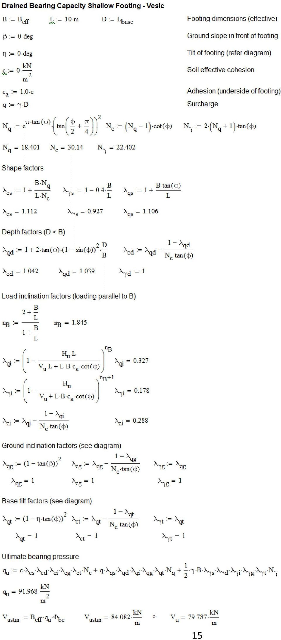
14 The bending capacity of the wall stem under action M u needs to be checked using the relevant material code. Detailed bearing capacity calculations: 14

15 15
16 16

17 17

18 References: Bowles, J.E. (1997) Foundation Analysis and Design, Fifth Edition, McGraw-Hill, New York, 1175 p. Brinch-Hansen, J (1970). A revised and extended formula for bearing capacity, Bulletin No. 28, Danish Geotechnical Institute, Copenhagen. Pender, M J (2015) Moment and Shear Capacity of Shallow Foundations at Fixed Vertical Load. Proc., 12th Australia New Zealand Conference on Geomechanics, Wellington. Vesic, A.S. (1975) Chap. 3, Foundation Engineering Handbook, 1 st. Ed., edited by Winterkorn and Fang, Van Nostrand Reinhold, 751 p. 18
 Chap. 3, Foundation Engineering Handbook, 1 st.")
REINFORCED CONCRETE. Reinforced Concrete Design. A Fundamental Approach - Fifth Edition. Walls are generally used to provide lateral support for:
 HANDOUT REINFORCED CONCRETE Reinforced Concrete Design A Fundamental Approach - Fifth Edition RETAINING WALLS Fifth Edition A. J. Clark School of Engineering Department of Civil and Environmental Engineering
Earth Pressure and Retaining Wall Basics for Non-Geotechnical Engineers
 PDHonline Course C155 (2 PDH) Earth Pressure and Retaining Wall Basics for Non-Geotechnical Engineers Instructor: Richard P. Weber, P.E. 2012 PDH Online PDH Center 5272 Meadow Estates Drive Fairfax, VA
vulcanhammer.net This document downloaded from
 This document downloaded from vulcanhammer.net since 1997, your source for engineering information for the deep foundation and marine construction industries, and the historical site for Vulcan Iron Works
Module 7 (Lecture 24 to 28) RETAINING WALLS
 RETAINING WALLS") Module 7 (Lecture 24 to 28) RETAINING WALLS Topics 24.1 INTRODUCTION 24.2 GRAVITY AND CANTILEVER WALLS 24.3 PROPORTIONING RETAINING WALLS 24.4 APPLICATION OF LATERAL EARTH PRESSURE THEORIES TO DESIGN 24.5
Module 7 (Lecture 24 to 28) RETAINING WALLS Topics 24.1 INTRODUCTION 24.2 GRAVITY AND CANTILEVER WALLS 24.3 PROPORTIONING RETAINING WALLS 24.4 APPLICATION OF LATERAL EARTH PRESSURE THEORIES TO DESIGN 24.5
EN 1997-1 Eurocode 7. Section 10 Hydraulic Failure Section 11 Overall Stability Section 12 Embankments. Trevor L.L. Orr Trinity College Dublin Ireland
 EN 1997 1: Sections 10, 11 and 12 Your logo Brussels, 18-20 February 2008 Dissemination of information workshop 1 EN 1997-1 Eurocode 7 Section 10 Hydraulic Failure Section 11 Overall Stability Section
Outline MICROPILES SUBJECT TO LATERAL LOADING. Dr. Jesús Gómez, P.E.
 MICROPILES SUBJECT TO LATERAL LOADING Dr. Jesús Gómez, P.E. Micropile Design and Construction Seminar Las Vegas, NV April 3-4, 2008 Outline When are micropiles subject to lateral load? How do we analyze
PDHonline Course S151A (1 PDH) Steel Sheet Piling. Instructor: Matthew Stuart, PE, SE. PDH Online PDH Center
 Steel Sheet Piling. Instructor: Matthew Stuart, PE, SE. PDH Online PDH Center") PDHonline Course S151A (1 PDH) Steel Sheet Piling Instructor: Matthew Stuart, PE, SE 2012 PDH Online PDH Center 5272 Meadow Estates Drive Fairfax, VA 22030-6658 Phone & Fax: 703-988-0088 www.pdhonline.org
PDHonline Course S151A (1 PDH) Steel Sheet Piling Instructor: Matthew Stuart, PE, SE 2012 PDH Online PDH Center 5272 Meadow Estates Drive Fairfax, VA 22030-6658 Phone & Fax: 703-988-0088 www.pdhonline.org
METHODS FOR ACHIEVEMENT UNIFORM STRESSES DISTRIBUTION UNDER THE FOUNDATION
 International Journal of Civil Engineering and Technology (IJCIET) Volume 7, Issue 2, March-April 2016, pp. 45-66, Article ID: IJCIET_07_02_004 Available online at http://www.iaeme.com/ijciet/issues.asp?jtype=ijciet&vtype=7&itype=2
Module 5 (Lectures 17 to 19) MAT FOUNDATIONS
 MAT FOUNDATIONS") Module 5 (Lectures 17 to 19) MAT FOUNDATIONS Topics 17.1 INTRODUCTION Rectangular Combined Footing: Trapezoidal Combined Footings: Cantilever Footing: Mat foundation: 17.2 COMMON TYPES OF MAT FOUNDATIONS
Module 5 (Lectures 17 to 19) MAT FOUNDATIONS Topics 17.1 INTRODUCTION Rectangular Combined Footing: Trapezoidal Combined Footings: Cantilever Footing: Mat foundation: 17.2 COMMON TYPES OF MAT FOUNDATIONS
EVALUATION OF SEISMIC RESPONSE - FACULTY OF LAND RECLAMATION AND ENVIRONMENTAL ENGINEERING -BUCHAREST
 EVALUATION OF SEISMIC RESPONSE - FACULTY OF LAND RECLAMATION AND ENVIRONMENTAL ENGINEERING -BUCHAREST Abstract Camelia SLAVE University of Agronomic Sciences and Veterinary Medicine of Bucharest, 59 Marasti
Appendix A Sub surface displacements around excavations Data presented in Xdisp sample file
 Appendix A Sub surface displacements around excavations Data presented in Xdisp sample file Notation B1 = lowest level of basement slab c = cohesion E = drained Young s Modulus Eu = undrained Young s Modulus
FOUNDATION TECHNICAL CATEGORY 3 (TC3) AUGUST 2012
 AUGUST 2012") FOUNDATION TECHNICAL CATEGORY 3 (TC3) AUGUST 2012 Building and Housing has published technical guidance for foundation repairs and reconstruction for residential properties in green zone Foundation Technical
FOUNDATION TECHNICAL CATEGORY 3 (TC3) AUGUST 2012 Building and Housing has published technical guidance for foundation repairs and reconstruction for residential properties in green zone Foundation Technical
How To Model A Shallow Foundation
 Finite Element Analysis of Elastic Settlement of Spreadfootings Founded in Soil Jae H. Chung, Ph.D. Bid Bridge Software Institute t University of Florida, Gainesville, FL, USA Content 1. Background 2.
THE DEVELOPMENT OF DESIGN METHODS FOR REINFORCED AND UNREINFORCED MASONRY BASEMENT WALLS J.J. ROBERTS
 THE DEVELOPMENT OF DESIGN METHODS FOR REINFORCED AND UNREINFORCED MASONRY BASEMENT WALLS J.J. ROBERTS Technical Innovation Consultancy Emeritus Professor of Civil Engineering Kingston University, London.
Foundations 65 5 FOUNDATIONS. by Richard Chylinski, FAIA and Timothy P. McCormick, P.E. Seismic Retrofit Training
 Foundations 65 5 FOUNDATIONS by Richard Chylinski, FAIA and Timothy P. McCormick, P.E. 66 Foundations Foundations 67 FOUNDATIONS Let's assume that the retrofit has been done correctly from the roofline
National Council of Examiners for Engineering and Surveying. Principles and Practice of Engineering Structural Examination
 Structural Effective Beginning with the April 2011 The structural engineering exam is a breadth and exam examination offered in two components on successive days. The 8-hour Vertical Forces (Gravity/Other)
PDCA Driven-Pile Terms and Definitions
 PDCA Driven-Pile Terms and Definitions This document is available for free download at piledrivers.org. Preferred terms are descriptively defined. Potentially synonymous (but not preferred) terms are identified
ESTIMATION OF UNDRAINED SETTLEMENT OF SHALLOW FOUNDATIONS ON LONDON CLAY
 International Conference on Structural and Foundation Failures August 2-4, 2004, Singapore ESTIMATION OF UNDRAINED SETTLEMENT OF SHALLOW FOUNDATIONS ON LONDON CLAY A. S. Osman, H.C. Yeow and M.D. Bolton
DESIGN GUIDELINES FOR EARTH RETENTION
 DESIGN GUIDELINES FOR EARTH RETENTION Strata Systems, Inc. 380 Dahlonega Rd., Suite 200 Cumming, GA 30040 USA www.geogrid.com TABLE OF CONTENTS MECHANICS OF RETAINING WALLS... 3 THE STRATAWEB SOLUTION...4
EARTH PRESSURE AND HYDRAULIC PRESSURE
 CHAPTER 9 EARTH PRESSURE AND HYDRAULIC PRESSURE - C9-1 - CHAPTER 9 EARTH PRESSURE AND HYDRAULIC PRESSURE General This chapter deals with earth pressure and hydraulic pressure acting on exterior basement
VERTICAL MICROPILE LATERAL LOADING. Andy Baxter, P.G.
 EFFICIENT DESIGN OF VERTICAL MICROPILE SYSTEMS TO LATERAL LOADING Dr. Jesús Gómez, P.E. PE Andy Baxter, P.G. Outline When are micropiles subject to lateral load? How do we analyze them? Shear Friction
Report on. Wind Resistance of Signs supported by. Glass Fiber Reinforced Concrete (GFRC) Pillars
 Pillars") Report on Wind Resistance of Signs supported by Glass Fiber Reinforced Concrete (GFRC) Pillars Prepared for US Sign and Fabrication Corporation January, 2006 SUMMARY This study found the attachment of
Report on Wind Resistance of Signs supported by Glass Fiber Reinforced Concrete (GFRC) Pillars Prepared for US Sign and Fabrication Corporation January, 2006 SUMMARY This study found the attachment of
Load and Resistance Factor Geotechnical Design Code Development in Canada. by Gordon A. Fenton Dalhousie University, Halifax, Canada
 Load and Resistance Factor Geotechnical Design Code Development in Canada by Gordon A. Fenton Dalhousie University, Halifax, Canada 1 Overview 1. Past: Where we ve been allowable stress design partial
Guidance for building in toe slump areas of mass movement in the Port Hills (Class II and Class III)
") November 2013 Guidance for building in toe slump areas of mass movement in the Port Hills (Class II and Class III) Supplementary guidance to Guidance on repairing and rebuilding houses affected by the
November 2013 Guidance for building in toe slump areas of mass movement in the Port Hills (Class II and Class III) Supplementary guidance to Guidance on repairing and rebuilding houses affected by the
FOUNDATION DESIGN. Instructional Materials Complementing FEMA 451, Design Examples
 FOUNDATION DESIGN Proportioning elements for: Transfer of seismic forces Strength and stiffness Shallow and deep foundations Elastic and plastic analysis Foundation Design 14-1 Load Path and Transfer to
Laterally Loaded Piles
 Laterally Loaded Piles 1 Soil Response Modelled by p-y Curves In order to properly analyze a laterally loaded pile foundation in soil/rock, a nonlinear relationship needs to be applied that provides soil
IS THAT LINER THICK ENOUGH?
 IS THAT LINER THICK ENOUGH? Philip McFarlane, Opus International Consultants Ltd ABSTRACT The amount of pipeline rehabilitation being undertaken in New Zealand is increasing each year. Larger diameter
Geotechnical Building Works (GBW) Submission Requirements
 Submission Requirements") Building Control (Amendment) Act 2012 and Regulations 2012: Geotechnical Building Works (GBW) Submission Requirements Building Engineering Group Building and Construction Authority May 2015 Content : 1.
Building Control (Amendment) Act 2012 and Regulations 2012: Geotechnical Building Works (GBW) Submission Requirements Building Engineering Group Building and Construction Authority May 2015 Content : 1.
Chapter 3 DESIGN AND CONSTRUCTION FEATURES IMPORTANT TO SEISMIC PERFORMANCE
 Chapter 3 DESIGN AND CONSTRUCTION FEATURES IMPORTANT TO SEISMIC PERFORMANCE To satisfy the performance goals of the NEHRP Recommended Seismic Provisions, a number of characteristics are important to the
Property Inspection. 83A Ascot Avenue North New Brighton Christchurch STRUCTURAL REPORT
 Property Inspection 83A Ascot Avenue North New Brighton Christchurch STRUCTURAL REPORT March 2013 This document has been prepared for the benefit of Clint Marston. No liability is accepted by this company
INTRODUCTION TO SOIL MODULI. Jean-Louis BRIAUD 1
 INTRODUCTION TO SOIL MODULI By Jean-Louis BRIAUD 1 The modulus of a soil is one of the most difficult soil parameters to estimate because it depends on so many factors. Therefore when one says for example:
Design of Steel Structures Prof. S.R.Satish Kumar and Prof. A.R.Santha Kumar. The design of any foundation consists of following two parts.
 8.7. Design procedure for foundation The design of any foundation consists of following two parts. 8.7.1 Stability analysis Stability analysis aims at removing the possibility of failure of foundation
Requirements for an Excavation and Lateral Support Plan Building (Administration) Regulation 8(1)(bc)
 Regulation 8(1)(bc)") Buildings Department Practice Note for Authorized Persons, Registered Structural Engineers and Registered Geotechnical Engineers APP-57 Requirements for an Excavation and Lateral Support Plan Building
Buildings Department Practice Note for Authorized Persons, Registered Structural Engineers and Registered Geotechnical Engineers APP-57 Requirements for an Excavation and Lateral Support Plan Building
DESIGN: (SUBSTRUCTURES, SPECIAL STRUCTURES AND MATERIALS) PART 12 BD 31/01 THE DESIGN OF BURIED CONCRETE BOX AND PORTAL FRAME STRUCTURES SUMMARY
 PART 12 BD 31/01 THE DESIGN OF BURIED CONCRETE BOX AND PORTAL FRAME STRUCTURES SUMMARY") DESIGN MANUAL FOR ROADS AND BRIDGES VOLUME 2 SECTION 2 HIGHWAY STRUCTURE DESIGN: (SUBSTRUCTURES, SPECIAL STRUCTURES AND MATERIALS) SPECIAL STRUCTURES PART 12 BD 31/01 THE DESIGN OF BURIED CONCRETE BOX
DESIGN MANUAL FOR ROADS AND BRIDGES VOLUME 2 SECTION 2 HIGHWAY STRUCTURE DESIGN: (SUBSTRUCTURES, SPECIAL STRUCTURES AND MATERIALS) SPECIAL STRUCTURES PART 12 BD 31/01 THE DESIGN OF BURIED CONCRETE BOX
HOW TO DESIGN CONCRETE STRUCTURES Foundations
 HOW TO DESIGN CONCRETE STRUCTURES Foundations Instructions for the Members of BIBM, CEMBUREAU, EFCA and ERMCO: It is the responsibility of the Members (national associations) of BIBM, CEMBUREAU, EFCA and
Estimation of Adjacent Building Settlement During Drilling of Urban Tunnels
 Estimation of Adjacent Building During Drilling of Urban Tunnels Shahram Pourakbar 1, Mohammad Azadi 2, Bujang B. K. Huat 1, Afshin Asadi 1 1 Department of Civil Engineering, University Putra Malaysia
EXAMPLE 1 DESIGN OF CANTILEVERED WALL, GRANULAR SOIL
 EXAMPLE DESIGN OF CANTILEVERED WALL, GRANULAR SOIL A sheet pile wall is required to support a 2 excavation. The soil is uniform as shown in the figure. To take into account the friction between the wall
4B-2. 2. The stiffness of the floor and roof diaphragms. 3. The relative flexural and shear stiffness of the shear walls and of connections.
 Shear Walls Buildings that use shear walls as the lateral force-resisting system can be designed to provide a safe, serviceable, and economical solution for wind and earthquake resistance. Shear walls
Recommended Specifications, Commentaries, and Example Problems
 Draft Final Report Volume 2 to the NATIONAL COOPERATIVE HIGHWAY RESEARCH PROGRAM (NCHRP) on Project 12-70 Seismic Analysis and Design of Retaining Walls, Buried Structures, Slopes, and Embankments Recommended
GUIDELINE FOR HAND HELD SHEAR VANE TEST
 GUIDELINE FOR HAND HELD SHEAR VANE TEST NZ GEOTECHNICAL SOCIETY INC August 2001 CONTENTS Page 1.0 Introduction 2 2.0 Background 2 3.0 Recommended Practice 3 4.0 Undrained Shear Strength 3 5.0 Particular
Numerical Simulation of CPT Tip Resistance in Layered Soil
 Numerical Simulation of CPT Tip Resistance in Layered Soil M.M. Ahmadi, Assistant Professor, mmahmadi@sharif.edu Dept. of Civil Engineering, Sharif University of Technology, Tehran, Iran Abstract The paper
4.3 Results... 27 4.3.1 Drained Conditions... 27 4.3.2 Undrained Conditions... 28 4.4 References... 30 4.5 Data Files... 30 5 Undrained Analysis of
 Table of Contents 1 One Dimensional Compression of a Finite Layer... 3 1.1 Problem Description... 3 1.1.1 Uniform Mesh... 3 1.1.2 Graded Mesh... 5 1.2 Analytical Solution... 6 1.3 Results... 6 1.3.1 Uniform
STRUCTURES. 1.1. Excavation and backfill for structures should conform to the topic EXCAVATION AND BACKFILL.
 STRUCTURES 1. General. Critical structures may impact the integrity of a flood control project in several manners such as the excavation for construction of the structure, the type of foundation, backfill
Development of Guidance Information for the Repair and Rebuilding of Houses Following the Canterbury Earthquake Series
 Development of Guidance Information for the Repair and Rebuilding of Houses Following the Canterbury Earthquake Series Graeme J Beattie (1) 1. Principal Structural Engineer, BRANZ Ltd, Private Bag 50908,
Page & Turnbull imagining change in historic environments through design, research, and technology
 DCI+SDE STRUCTURAL EVALUATIONS OFFICE BUILDING, TOOL SHED & WATER TANK, AND BLACKSMITH & MACHINE SHOP BUILDINGS SAN FRANCISCO, CALIFORNIA [14290] PRIMARY PROJECT CONTACT: H. Ruth Todd, FAIA, AICP, LEED
Miss S. S. Nibhorkar 1 1 M. E (Structure) Scholar,
 Scholar,") Volume, Special Issue, ICSTSD Behaviour of Steel Bracing as a Global Retrofitting Technique Miss S. S. Nibhorkar M. E (Structure) Scholar, Civil Engineering Department, G. H. Raisoni College of Engineering
Volume, Special Issue, ICSTSD Behaviour of Steel Bracing as a Global Retrofitting Technique Miss S. S. Nibhorkar M. E (Structure) Scholar, Civil Engineering Department, G. H. Raisoni College of Engineering
SPECIFICATION FOR DYNAMIC CONSOLIDATION / DYNAMIC REPLACEMENT
 SPECIFICATION FOR DYNAMIC CONSOLIDATION / DYNAMIC REPLACEMENT 1.0 SOIL IMPROVEMENT 1.1 General Soil Investigation Information are provided in Part B1 annex as a guide to the Contractor for his consideration
Wang, L., Gong, C. "Abutments and Retaining Structures." Bridge Engineering Handbook. Ed. Wai-Fah Chen and Lian Duan Boca Raton: CRC Press, 2000
 Wang, L., Gong, C. "Abutments and Retaining Structures." Bridge Engineering Handbook. Ed. Wai-Fah Chen and Lian Duan Boca Raton: CRC Press, 000 9 Abutments and Retaining Structures Linan Wang California
INTRODUCTION TO LIMIT STATES
 4 INTRODUCTION TO LIMIT STATES 1.0 INTRODUCTION A Civil Engineering Designer has to ensure that the structures and facilities he designs are (i) fit for their purpose (ii) safe and (iii) economical and
An Example of Using ReSSA in Complex Geometry of Reinforced Tiered Slope Introduction Background
 An Example of Using ReSSA in Complex Geometry of Reinforced Tiered Slope By Dov Leshchinsky Copyright 2001, ADAMA Engineering, Inc. All Rights Reserved Introduction Geosynthetic reinforced soil structures
SLAB DESIGN. Introduction ACI318 Code provides two design procedures for slab systems:
 Reading Assignment SLAB DESIGN Chapter 9 of Text and, Chapter 13 of ACI318-02 Introduction ACI318 Code provides two design procedures for slab systems: 13.6.1 Direct Design Method (DDM) For slab systems
EUROCODE 7 & POLISH PRACTICE
 EUROCODE 7 & POLISH PRACTICE Implementation of Eurocode 7 in Poland Beata Gajewska Road and Bridge Research Institute In Poland the designing with limit states and partial factors was introduced in 1974.
BRIDGE RESTORATION AND LANDSLIDE CORRECTION USING STRUCTURAL PIER AND GRADE BEAM
 BRIDGE RESTORATION AND LANDSLIDE CORRECTION USING STRUCTURAL PIER AND GRADE BEAM Swaminathan Srinivasan, P.E., M.ASCE H.C. Nutting/Terracon David Tomley, P.E., M.ASCE KZF Design Delivering Success for
DISTRIBUTION OF LOADSON PILE GROUPS
 C H A P T E R 7 DISTRIBUTION OF LOADSON PILE GROUPS Section I. DESIGN LOADS 7-1. Basic design. The load carried by an individual pile or group of piles in a foundation depends upon the structure concerned
Technical handbook Panel Anchoring System
 1 Basic principles of sandwich panels 3 Design conditions 4 Basic placement of anchors and pins 9 Large elements (muliple rows) 10 Small elements (two rows) 10 Turned elements 10 Slender elements 10 Cantilevering
stretches and exercises
 stretches and exercises The enclosed sheets contain stretches and exercises which can be used to delay and minimise the development of contractures and deformities occurring in children with Duchenne muscular
ick Foundation Analysis and Design
 ick Foundation Analysis and Design Work: ick Foundation Location: Description: Prop: Detail analysis and design of ick patented foundation for Wind Turbine Towers Gestamp Hybrid Towers Date: 31/10/2012
ANNEX D1 BASIC CONSIDERATIONS FOR REVIEWING STUDIES IN THE DETAILED RISK ASSESSMENT FOR SAFETY
 ANNEX D1 BASIC CONSIDERATIONS FOR REVIEWING STUDIES IN THE DETAILED RISK ASSESSMENT FOR SAFETY ANNEX D1: BASIC CONSIDERATIONS FOR REVIEWING STUDIES IN DRA FOR SAFETY D1-1 ANNEX D1 BASIC CONSIDERATIONS
Soil Strength. Performance Evaluation of Constructed Facilities Fall 2004. Prof. Mesut Pervizpour Office: KH #203 Ph: x4046
 ENGR-627 Performance Evaluation of Constructed Facilities, Lecture # 4 Performance Evaluation of Constructed Facilities Fall 2004 Prof. Mesut Pervizpour Office: KH #203 Ph: x4046 1 Soil Strength 2 Soil
Settlement of Precast Culverts Under High Fills; The Influence of Construction Sequence and Structural Effects of Longitudinal Strains
 Settlement of Precast Culverts Under High Fills; The Influence of Construction Sequence and Structural Effects of Longitudinal Strains Doug Jenkins 1, Chris Lawson 2 1 Interactive Design Services, 2 Reinforced
Guidance on Detailed Engineering Evaluation of Nonresidential buildings
 Guidance on Detailed Engineering Evaluation of Nonresidential buildings Part 3 Technical Guidance Section 5 Foundations Draft Prepared by the Engineering Advisory Group Read in Conjunction with Sections
Important Points: Timing: Timing Evaluation Methodology Example Immediate First announcement of building damage
 3.3. Evaluation of Building Foundation Damage Basic Terminology: Damage: Destruction, deformation, inclination and settlement of a building foundation caused by an earthquake. Damage grade: Degree of danger
COSMOS 2012: Earthquakes in Action COSMOS 2012
 COSMOS 2012 What is SFSI and why is it important? Soil issues in Earthquakes Structures where SFSI important Retaining structures (lateral earth pressure) Foundations (spread and pile footings, bearing
Chapter 6 ROOF-CEILING SYSTEMS
 Chapter 6 ROOF-CEILING SYSTEMS Woodframe roof-ceiling systems are the focus of this chapter. Cold-formed steel framing for a roof-ceiling system also is permitted by the IRC but will not be discussed;
Stability. Security. Integrity.
 Stability. Security. Integrity. PN #MBHPT Foundation Supportworks provides quality helical pile systems for both new construction and retrofit applications. 288 Helical Pile System About Foundation Supportworks
A N Beal EARTH RETAINING STRUCTURES - worked examples 1
 A N Beal EARTH RETAINING STRUCTURES - worked examples 1 Worked examples of retaining wall design to BS8002 The following worked examples have been prepared to illustrate the application of BS8002 to retaining
Applying a circular load. Immediate and consolidation settlement. Deformed contours. Query points and query lines. Graph query.
 Quick Start Tutorial 1-1 Quick Start Tutorial This quick start tutorial will cover some of the basic features of Settle3D. A circular load is applied to a single soil layer and settlements are examined.
Aluminium systems profile selection
 Aluminium systems profile selection The purpose of this document is to summarise the way that aluminium profile selection should be made, based on the strength requirements for each application. Curtain
Technical Notes 3B - Brick Masonry Section Properties May 1993
 Technical Notes 3B - Brick Masonry Section Properties May 1993 Abstract: This Technical Notes is a design aid for the Building Code Requirements for Masonry Structures (ACI 530/ASCE 5/TMS 402-92) and Specifications
REPAIR AND STRENGTHENING OF HISTORICAL CONCRETE BRIDGE OVER VENTA RIVER IN LATVIA
 1 REPAIR AND STRENGTHENING OF HISTORICAL CONCRETE BRIDGE OVER VENTA RIVER IN LATVIA Verners Straupe, M.sc.eng., Rudolfs Gruberts, dipl. eng. JS Celuprojekts, Murjanu St. 7a, Riga, LV 1024, Latvia e-mail:
PILE FOUNDATIONS FM 5-134
 C H A P T E R 6 PILE FOUNDATIONS Section I. GROUP BEHAVIOR 6-1. Group action. Piles are most effective when combined in groups or clusters. Combining piles in a group complicates analysis since the characteristics
Bearing Capacity (Daya Dukung Tanah)
") Bearing Capacity (Daya Dukung Tanah) Dr. Ir.H. Erizal, MAgr Definisi Daya dukung yang diizinkan (allowable bearing cap.) tekanan maksimum yang dapat diaplikasikan ke tanah dimana 2 kondisi diatas dipenuhi.
Bearing Capacity (Daya Dukung Tanah) Dr. Ir.H. Erizal, MAgr Definisi Daya dukung yang diizinkan (allowable bearing cap.) tekanan maksimum yang dapat diaplikasikan ke tanah dimana 2 kondisi diatas dipenuhi.
Reinforced Concrete Design
 FALL 2013 C C Reinforced Concrete Design CIVL 4135 ii 1 Chapter 1. Introduction 1.1. Reading Assignment Chapter 1 Sections 1.1 through 1.8 of text. 1.2. Introduction In the design and analysis of reinforced
Retaining Wall Global Stability & AASHTO LRFD Unnecessary, Unreasonable Guideline Changes Result in Huge Wastes of Money at Some Wall Locations
 Retaining Wall Global Stability & AASHTO LRFD Unnecessary, Unreasonable Guideline Changes Result in Huge Wastes of Money at Some Wall Locations The implementation of the AASHTO LRFD Bridge Design Specifications
6 RETROFITTING POST & PIER HOUSES
 Retrofitting Post & Pier Houses 71 6 RETROFITTING POST & PIER HOUSES by James E. Russell, P.E. 72 Retrofitting Post & Pier Houses Retrofitting Post & Pier Houses 73 RETROFITTING POST AND PIER HOUSES This
Engineered, Time-Tested Foundation Repairs for Settlement in Residential and Light Commercial Structures. The Leading Edge.
 TM TM Engineered, Time-Tested Foundation Repairs for Settlement in Residential and Light Commercial Structures. SM The Leading Edge. 10 One Major Causes of foundation settlement or more conditions may
Simplifying design and construction. Alan Tovey, Director The Basement Information Centre
 Simplifying design and construction Alan Tovey, Director The Basement Information Centre Simplifying design and construction Grades of construction Construction options Design and waterproofing issues
Geotechnical Investigation Reports and Foundation Recommendations - Scope for Improvement - Examples
 Geotechnical Investigation Reports and Foundation Recommendations - Scope for Improvement - Examples Prof. V.S.Raju (Formerly: Director, IIT Delhi & Professor and Dean, IIT Madras) Email: rajuvs_b@yahoo.com
Sisal Composite Ltd. Apparel 4 Ltd. JM Knit Ltd. Natun Para, Hemayetpur, Savar, Dhaka-1340 (23.789416N,90.266135E)
") Revision: issue 1 Date: 11 June 2014 Sisal Composite Ltd. Apparel 4 Ltd. JM Knit Ltd. Natun Para, Hemayetpur, Savar, Dhaka-1340 (23.789416N,90.266135E) 24 th May 2014 Structural Inspection Report Observations
Revision: issue 1 Date: 11 June 2014 Sisal Composite Ltd. Apparel 4 Ltd. JM Knit Ltd. Natun Para, Hemayetpur, Savar, Dhaka-1340 (23.789416N,90.266135E) 24 th May 2014 Structural Inspection Report Observations
Rehabilitation of Existing Foundation Building to Resist Lateral and Vertical Loads
 International Journal of Current Microbiology and Applied Sciences ISSN: 2319-7706 Volume 3 Number 12 (2014) pp. 950-961 http://www.ijcmas.com Original Research Article Rehabilitation of Existing Foundation
9.8.1.1. General (1) This Section applies to the design and construction of interior and exterior stairs, steps, ramps, railings and guards.
 This Section applies to the design and construction of interior and exterior stairs, steps, ramps, railings and guards.") Section 9.8. Stairs, Ramps, Handrails and Guards 9.8.1. Application 9.8.1.1. General (1) This Section applies to the design and construction of interior and exterior stairs, steps, ramps, railings and
Section 9.8. Stairs, Ramps, Handrails and Guards 9.8.1. Application 9.8.1.1. General (1) This Section applies to the design and construction of interior and exterior stairs, steps, ramps, railings and
DESIGN SPECIFICATIONS FOR HIGHWAY BRIDGES PART V SEISMIC DESIGN
 DESIGN SPECIFICATIONS FOR HIGHWAY BRIDGES PART V SEISMIC DESIGN MARCH 2002 CONTENTS Chapter 1 General... 1 1.1 Scope... 1 1.2 Definition of Terms... 1 Chapter 2 Basic Principles for Seismic Design... 4
ENCE 4610 Foundation Analysis and Design
 This image cannot currently be displayed. ENCE 4610 Foundation Analysis and Design Shallow Foundations Total and Differential Settlement Schmertmann s Method This image cannot currently be displayed. Strength
Section 5A: Guide to Designing with AAC
 Section 5A: Guide to Designing with AAC 5A.1 Introduction... 3 5A.3 Hebel Reinforced AAC Panels... 4 5A.4 Hebel AAC Panel Design Properties... 6 5A.5 Hebel AAC Floor and Roof Panel Spans... 6 5A.6 Deflection...
Geotechnical Measurements and Explorations Prof. Nihar Ranjan Patra Department of Civil Engineering Indian Institute of Technology, Kanpur
 Geotechnical Measurements and Explorations Prof. Nihar Ranjan Patra Department of Civil Engineering Indian Institute of Technology, Kanpur Lecture No. # 13 (Refer Slide Time: 00:18) So last class, it was
Embedded Retaining Wall Design Engineering or Paradox?
 Embedded Retaining Wall Design Engineering or Paradox? A personal viewpoint by A.Y. Chmoulian, associate at Royal Haskoning Introduction Retaining wall design theory is a complicated subject with a long
SEISMIC UPGRADE OF OAK STREET BRIDGE WITH GFRP
 13 th World Conference on Earthquake Engineering Vancouver, B.C., Canada August 1-6, 2004 Paper No. 3279 SEISMIC UPGRADE OF OAK STREET BRIDGE WITH GFRP Yuming DING 1, Bruce HAMERSLEY 2 SUMMARY Vancouver
Validation of methods for assessing tunnelling-induced settlements on piles
 Validation of methods for assessing tunnelling-induced settlements on piles Mike Devriendt, Arup Michael Williamson, University of Cambridge & Arup technical note Abstract For tunnelling projects, settlements
GEOTECHNICAL ENGINEERING FORMULAS. A handy reference for use in geotechnical analysis and design
 GEOTECHNICAL ENGINEERING FORMULAS A handy reference for use in geotechnical analysis and design TABLE OF CONTENTS Page 1. SOIL CLASSIFICATION...3 1.1 USCS: Unified Soil Classification System...3 1.1.1
BEARING CAPACITY AND SETTLEMENT RESPONSE OF RAFT FOUNDATION ON SAND USING STANDARD PENETRATION TEST METHOD
 SENRA Academic Publishers, British Columbia Vol., No. 1, pp. 27-2774, February 20 Online ISSN: 0-353; Print ISSN: 17-7 BEARING CAPACITY AND SETTLEMENT RESPONSE OF RAFT FOUNDATION ON SAND USING STANDARD
Optimum proportions for the design of suspension bridge
 Journal of Civil Engineering (IEB), 34 (1) (26) 1-14 Optimum proportions for the design of suspension bridge Tanvir Manzur and Alamgir Habib Department of Civil Engineering Bangladesh University of Engineering
NCMA TEK CONCRETE MASONRY FOUNDATION WALL DETAILS. TEK 5-3A Details (2003)
") NCMA TEK National Concrete Masonry Association an information series from the national authority on concrete masonry technology CONCRETE MASONRY FOUNDATION WALL DETAILS TEK 5-3A Details (2003) Keywords:
NCMA TEK National Concrete Masonry Association an information series from the national authority on concrete masonry technology CONCRETE MASONRY FOUNDATION WALL DETAILS TEK 5-3A Details (2003) Keywords:
Comparison of Seismic Retrofitting Methods for Existing Foundations in Seismological Active Regions
 Comparison of Seismic Retrofitting Methods for Existing Foundations in Seismological Active Regions Peyman Amini Motlagh, Ali Pak Abstract Seismic retrofitting of important structures is essential in seismological
How to Design Helical Piles per the 2009 International Building Code
 ABSTRACT How to Design Helical Piles per the 2009 International Building Code by Darin Willis, P.E. 1 Helical piles and anchors have been used in construction applications for more than 150 years. The
Optimised Design for Soil Nailed Walls 1
 Optimised Design for Soil Nailed Walls 1 J A R Ortigao 1 and E M Palmeira 2 1 Federal University of Rio de Janeiro, Rio de Janeiro, Brazil 2 University of Brasília, Brasília, Brazil INTRODUCTION The first
Dimensional and Structural Data for Elliptical Pipes. PD 26 rev D 21/09/05
 Dimensional and Structural Data for Elliptical Pipes 21/09/05 Page 1 of 15 1. Foreword This document details a method for the structural design of Stanton Bonna Elliptical pipes for the common conditions
GEOTECHNICAL DESIGN ASPECTS OF BASEMENT RETAINING WALLS
 GEOTECHNICAL DESIGN ASPECTS OF BASEMENT RETAINING WALLS John Byrne Byrne Looby Partners John Byrne graduated from South Bank University in London with an Honours Degree in Civil Engineering in 1992. He
PART TWO GEOSYNTHETIC SOIL REINFORCEMENT. Martin Street Improvements, Fredonia, Wisconsin; Keystone Compac Hewnstone
 GEOSYNTHETIC SOIL REINFORCEMENT Martin Street Improvements, Fredonia, Wisconsin; Keystone Compac Hewnstone DESIGN MANUAL & KEYWALL OPERATING GUIDE GEOSYNTHETIC SOIL REINFORCEMENT Keystone retaining walls
SIENA STONE GRAVITY RETAINING WALL INSTALLATION SPECIFICATIONS. Prepared by Risi Stone Systems Used by permission.
 SIENA STONE GRAVITY RETAINING WALL INSTALLATION SPECIFICATIONS Prepared by Risi Stone Systems Used by permission. 1-800-UNILOCK www.unilock.com FOREWORD This outline specification has been prepared for
SEISMIC DESIGN. Various building codes consider the following categories for the analysis and design for earthquake loading:
 SEISMIC DESIGN Various building codes consider the following categories for the analysis and design for earthquake loading: 1. Seismic Performance Category (SPC), varies from A to E, depending on how the