Current Electricity continual movement of sustained charges. Potential (Voltage), Current, Resistance
|
|
|
- Francis Flowers
- 7 years ago
- Views:
Transcription
1 Current Electricity continual movement of sustained charges Potential (Voltage), Current, Resistance 1
2 Electric Current the flow of charge Two types of Current Where does the charge that moves come from? 2
3 Resistance (R) a quantity measuring the difficulty of charge movement. Factors that effect Resistance 3
4 OHM s Law Ohmic vs Non Ohmic Materials Graph 4
5 1.) What do the following units represent (a) J/C (b) C/s (c) V/m (d) N/C 2.) A lightening bolt delivers 35 coulombs of charge to the ground in 1/1000 of a second. (a) How many electrons are transferred, (b) What is the current of the lightening bolt. 3.) 9mC of charge passes through a cross section of wire in 3.5 seconds. (a) What is the current (b) How many electrons move through this section in 10 seconds (c) if the charge was doubled, what would the new current be 5
6 4.) A 10 m wire consists of 5m of copper followed by 5 m of aluminum of equal 1mm diameter. A potential difference of 80 V is placed across the composite wire (a) What is the total resistance (b) current flow throughout and (c) potential difference across aluminum and copper parts respectively. 6
7 Electric Power and Energy 7
8 Light Bulbs 8
9 Electric Energy 9
10 5.) A 12 V battery pushed a current of 0.50 A through a resistor. What is the resistance of the resistor and how many joules of energy does the battery loose in 1 minute 10
11 6.) A 150 W light bulb operates with a 120 V potential difference. (a) How much energy does it used in 2 hrs. (b) at a rate of $.08/ kw hr how much does it cost to operate the bulb for 2 hrs (c) If this bulb was connected to a 240 V source of potential difference, at what rate would it dissipate energy. 11
12 Electric Circuits 12
13 Open / Closed / Short Circuit 13
14 Types of circuits Series vs Parallel 14
15 Christmas Light Strings 15
16 Circuit Rules (potential, current, resistance) Series Parallel Currents Potential (voltage) Resistance 16
17 V = I x R S T E T P E T R 17
18 Conservation of Charge in a circuit Which is correct 18

19 Using Meters To Measure Current and Voltage Ammeter 19
20 Voltmeter 20
21 Circuit Problems A) A 4 Ω, 8 Ω and 12 Ω resistor are connected in series to a 24 V Battery. a) Draw the schematic, b) find all the currents and "potential drops" across each resistor 21
22 B) An 18 Ω, 9 Ω and 6 Ω resistor are connected in parallel. a) determine the equivalent resistance of the connected resistors b) the current in the 9 Ω resistor is 4 A, determine the currents and potentials in the other resistors. 22

23 Problem Pack 23

24 24
25 25
")
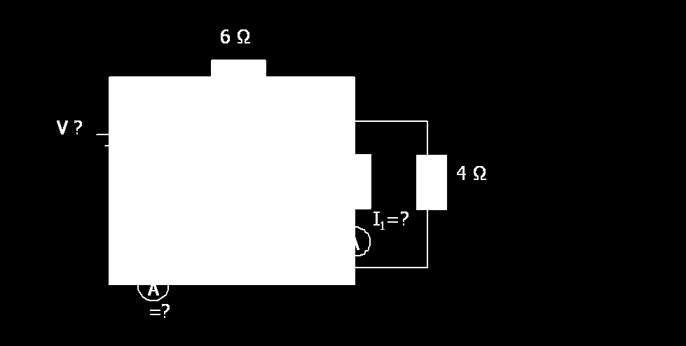
26 Combined Circuit 4) 26
27 5) 27
28 6) 28
29 7) 29
30 8) 30
31 31
32 REDRAWING CIRCUITS R1 R2 R3 R4 R2 R1 R3 R4 R5 32
33 R2 R4 R1 R3 R5 R1 R4 R3 R2 R5 R7 R6 33
34 R3 R5 R4 R2 R6 R1 R5 R6 R4 R3 R2 R1 34
35 R1 R2 R3 R4 R8 R5 R6 R7 35
36 9) 1Ω 5Ω 2Ω 3Ω 10 V 1Ω 36
37 10) 37
38 Fuses and Circuit Breakers 38
39 Will either fuse burn out? Prove it 39
40 Circuits w/ power An electric heater is rated at 1200 W, a toaster is rated at 1100 W, and an electric grill is rated at 1300 W. The three appliances are connected in parallel to a common 120 V circuit. (a) How much current does each appliance draw? (b) Is a 28.0 A circuit breaker sufficient in this situation? Explain. 40
41 Light Bulbs and Brightness Determined By? Recall how bulbs relate to voltage (100 W bulb) If hooked up in series original (single 100 W) series connection (50 / 100 W) Adding bulbs in series Removing bulbs in series 41
42 Parallel Bulbs Add / Remove a Bulb 42

43 Complex bulb connections How does the reading on Ammeter A change How do bulbs a, b, c brightness change Compare brightness of each bulb in new orientation 43
44 How does the reading on Ammeter A change Compare brightness of each bulb 44
45 Bulb X How does the reading on Ammeter A change How do bulbs a, b, c brightness change Compare brightness of each bulb in new orientation 45
46 Bulb X How does the reading on Ammeter A change How do bulbs a, b, c brightness change Compare brightness of each bulb in new orientation 46
47 Bulb X How does the reading on Ammeter A change How do bulbs a, b, c brightness change Compare brightness of each bulb in new orientation 47
48 EMF and Terminal Voltage 48
49 How to include EMF in a problem If not indicated If EMF given 49
50 Graph 50
51 EMF EXAMPLE. A 20 V emf battery with an internal resistance of 1 ohm is connected in series to two 5 ohm resistors. (a) Determine the terminal voltage of the battery. (b) Determine the energy dissipated by the external circuit in 1 minuts 51

52 Massive All Inclusion Circuit Question (w/o Kirchhoff rules) A student is provided with a 12.0 V battery of negligible internal resistance and four resistors with the following resistances: 100 Ω, 30 Ω, 20 Ω, and 10 Ω. The student also has plenty of wire of negligible resistance available to make connections as desired. a.) Using all of these components, draw a circuit diagram in which each resistor has nonzero current flowing through it, but in which the current from the battery is as small as possible. b.) Using all of these components, draw a circuit diagram in which each resistor has nonzero current flowing through it, but in which the current from the battery is as large as possible (without short circuiting the battery). The battery and resistors are now connected in the circuit shown c.) Determine the following for this circuit. i.) The current in the 10 Ω resistor ii.) The total power consumption of the circuit d.) Assuming that the current remains constant, how long will it take to provide a total of 10 kj of electrical energy to the circuit? The battery is replaced with a different battery of the same EMF but having internal resistance of 1 ohm e.) How will the power consumption of the external circuit be affected f.) What is the terminal voltage of this battery when connected in the circuit shown g.) The resistance free battery is returned to the circuit and the resistors are replaced with equal sized light bulbs B1, B2, B3 and B4, rank the brightness of each in order of increasing magnitude (Use = signs if bulbs have the same brightness) h.) If only Bulb B4 was removed, how would the brightness of the other bulbs be affected i.) If only Bulb B2 was removed, how would the brightness of the other bulbs be affected 52
 2) The loop rule (energy conservation")
53 Complex Combined Circuits and Kirchoff s Laws 1) The junction rule (charge conservation rule) 2) The loop rule (energy conservation rule) 53
54 Find Unknowns 54
55 2) Find I total 55
 Determine the magnitudes and directions of the currents through each resistor 9V 20 Ω x 12V I 2 = 0.")
56 3) For the circuit shown: The current through resistor R 2 is 0.33 A as shown. The batteries have emfs of ε 1 = 9.0 V and ε 2 = 12.0 V and the resistors have values of R 1 = 15Ω, R 2 = 20Ω, and R 3 = 32 Ω. 15 Ω y a) Determine the magnitudes and directions of the currents through each resistor 9V 20 Ω x 12V I 2 = 0.33 A 32 Ω b) Determine the potential difference from x > y 56
57 4) Random use of loop rule In the circuit shown above, what is the resistance R? 5) In the circuit shown above, the current in each battery is 0.04 ampere. a) What is the potential difference between the points x and y? b) Which point is at a higher potential, X or Y 57
58 Terminal Voltage > EMF??? 6) A 12 volt storage battery, with an internal resistance of 2 Ω, is being charged by a current of 2 amperes as shown in the diagram above. Under these circumstances, a voltmeter connected across the terminals of the battery will read (show wrong answer first) 58
59 Advanced Kirchoff Problem see handout on next page 7) Determine the magnitudes and directions of the currents through each resistor shown. The batteries have emfs of ε 1 = 9.0 V and ε 2 = 12.0 V and the resistors have values of R 1 = 15Ω, R 2 = 20Ω, and R 3 = 32 Ω. 9V 15 Ω y 20 Ω x 12V 32 Ω 59
60 60
61 Capacitors in Circuits 61
62 Capacitors in series when connected to a battery EQ. Capacitance (C EQ ) Charge (Q) Potential (voltage) (V) 62
63 Example 1.) A 0.40 μf and a 0.50 μf capacitor are connected in series to a 9 V emf source. Calculate the potential across each capacitor 63
64 Capacitors hooked to each other 64
65 EX 2.) A 1µF capacitor is connected to a 12 V battery an allowed to charge. It is then disconnected from the battery an attached to a 2 µf uncharged capacitor. (a) Determine the charge stored on the capacitor while connected to the battery (b) Determine the charge stored on each capacitor after being connected to one another 65
66 Capacitors in parallel with a battery vs Equivalent Capacitance (C EQ ) Voltage (V) Charge (Q) 66
67 Circuit Rules Summary Chart VIR VIR Resistors STET PETR Capacitors STER PETT 67
68 3.) 12.5 μ F cap C 1 is connected in series to a 6.25 μf cap C 2 and these are then connected in parallel to a 12.5 μf cap C 3. The whole combination is connected in parallel to 45 V emf source. a) How much charge is stored on each capacitor. b) How much total charge is stored 68
69 Inserting material between capacitors 1) Dielectrics 2) Conductors 69
70 Quick Summary Rules for changing Parallel Plates dimensions Capacitance C, is physical and changed based on C= ε o A / d 1) Isolated: NOT connected to battery Charge Q Potential V E Field 2) Connected to battery Charge Q Potential V E Field 70
71 RC circuits Series How to Treat the capacitor 1) At first 2) as time goes on 3) When fully charged 71
72 Parallel 1) At first 2) as time goes on 3) When fully charged 72
73 Combined Parallel and Series RC behavior depends on the configuration 4) (a) Determine the current flowing in the circuit when the switch is first flipped (b) Determine the current flowing in the circuit after a long time (c) Determine the energy and charge stored in the capacitor 73
 What is the potential at point a? (Let V = 0 at the negative terminal of the source.")
74 5.) Two resistors and two uncharged capacitors are arranged as shown in Fig ( R = 8.8, C = 0.24 µf) with a potential difference of 24 V across the combination. (a) What is the potential at point a? (Let V = 0 at the negative terminal of the source.) (Potential at a = the potential difference from a to c) (b) What is the potential at point b (Potential at b = potential diff b to c) (c) Find the energy in each cap 74
 Determine the energy and charge stored in the capacitor")
75 6) (a) Determine the current flowing in the circuit when the switch is first flipped on (b) Determine the current flowing in the circuit after a long time (c) Determine the energy and charge stored in the capacitor 75
76 7.) 2000B B3. Three identical resistors, each with resistance R, and a capacitor of F are connected to a 30 V battery with negligible internal resistance, as shown in the circuit diagram above. Switches I and S S 2 are initially closed, and switch 3 Sis initially open. A voltmeter is connected as shown. a. Determine the reading on the voltmeter. Switches S l and S 2 are now opened, and then switch S 3 is closed. b. Determine the charge Q on the capacitor after S 3 has been closed for a very long time. After the capacitor is fully charged, switches S 1 and S 2 remain open, switch S 3 remains closed, the plates are held fixed, and a conducting copper block is inserted midway between the plates, as shown below. The plates of the capacitor are separated by a distance of 1.0 mm, and the copper block has a thickness of 0.5 mm. c. i. What is the potential difference between the plates? ii. What is the electric field inside the copper block? iii. On the diagram above, draw arrows to clearly indicate the direction of the electric field between the plates. iv. Determine the magnitude of the electric field in each of the spaces between the plates and the copper block. 76
77 8) Into which circuit should the battery be connected to obtain the greatest steady power dissipation? (A) A (B) B (C) C (D) D (E) E Which circuit will retain stored energy if the battery is connected to it and then disconnected? (A) A (B) B (C) C (D) D (E) E 77
AP Physics Electricity and Magnetism #4 Electrical Circuits, Kirchoff s Rules
 Name Period AP Physics Electricity and Magnetism #4 Electrical Circuits, Kirchoff s Rules Dr. Campbell 1. Four 240 Ω light bulbs are connected in series. What is the total resistance of the circuit? What
PHYSICS 111 LABORATORY Experiment #3 Current, Voltage and Resistance in Series and Parallel Circuits
 PHYSCS 111 LABORATORY Experiment #3 Current, Voltage and Resistance in Series and Parallel Circuits This experiment is designed to investigate the relationship between current and potential in simple series
MULTIPLE CHOICE. Choose the one alternative that best completes the statement or answers the question.
 MULTIPLE CHOICE. Choose the one alternative that best completes the statement or answers the question. 1) If the voltage at a point in space is zero, then the electric field must be A) zero. B) positive.
7. What is the current in a circuit if 15 coulombs of electric charge move past a given point in 3 seconds? (1) 5 A (3) 18 A (2) 12 A (4) 45 A
 5 A (3) 18 A (2) 12 A (4) 45 A") 1. Compared to the number of free electrons in a conductor, the number of free electrons in an insulator of the same volume is less the same greater 2. Most metals are good electrical conductors because
1. Compared to the number of free electrons in a conductor, the number of free electrons in an insulator of the same volume is less the same greater 2. Most metals are good electrical conductors because
People s Physics Book
 The Big Ideas: The name electric current is given to the phenomenon that occurs when an electric field moves down a wire at close to the speed of light. Voltage is the electrical energy density (energy
Chapter 7 Direct-Current Circuits
 Chapter 7 Direct-Current Circuits 7. Introduction...7-7. Electromotive Force...7-3 7.3 Resistors in Series and in Parallel...7-5 7.4 Kirchhoff s Circuit Rules...7-7 7.5 Voltage-Current Measurements...7-9
= (0.400 A) (4.80 V) = 1.92 W = (0.400 A) (7.20 V) = 2.88 W
 (4.80 V) = 1.92 W = (0.400 A) (7.20 V) = 2.88 W") Physics 2220 Module 06 Homework 0. What are the magnitude and direction of the current in the 8 Ω resister in the figure? Assume the current is moving clockwise. Then use Kirchhoff's second rule: 3.00
Physics 2220 Module 06 Homework 0. What are the magnitude and direction of the current in the 8 Ω resister in the figure? Assume the current is moving clockwise. Then use Kirchhoff's second rule: 3.00
Series and Parallel Circuits
 Series and Parallel Circuits Direct-Current Series Circuits A series circuit is a circuit in which the components are connected in a line, one after the other, like railroad cars on a single track. There
Electrical Fundamentals Module 3: Parallel Circuits
 Electrical Fundamentals Module 3: Parallel Circuits PREPARED BY IAT Curriculum Unit August 2008 Institute of Applied Technology, 2008 ATE310- Electrical Fundamentals 2 Module 3 Parallel Circuits Module
3.- What atom s particle moves through a conductor material? 4.- Which are the electric components of an elemental electric circuit?
 1.- What is electricity? 2.- Write down the name of the atom s particles. 3.- What atom s particle moves through a conductor material? 4.- Which are the electric components of an elemental electric circuit?
Chapter 7. DC Circuits
 Chapter 7 DC Circuits 7.1 Introduction... 7-3 Example 7.1.1: Junctions, branches and loops... 7-4 7.2 Electromotive Force... 7-5 7.3 Electrical Energy and Power... 7-9 7.4 Resistors in Series and in Parallel...
Chapter 13: Electric Circuits
 Chapter 13: Electric Circuits 1. A household circuit rated at 120 Volts is protected by a fuse rated at 15 amps. What is the maximum number of 100 watt light bulbs which can be lit simultaneously in parallel
Circuits. The light bulbs in the circuits below are identical. Which configuration produces more light? (a) circuit I (b) circuit II (c) both the same
 circuit I (b) circuit II (c) both the same") Circuits The light bulbs in the circuits below are identical. Which configuration produces more light? (a) circuit I (b) circuit II (c) both the same Circuit II has ½ current of each branch of circuit
Circuits The light bulbs in the circuits below are identical. Which configuration produces more light? (a) circuit I (b) circuit II (c) both the same Circuit II has ½ current of each branch of circuit
CHAPTER 28 ELECTRIC CIRCUITS
 CHAPTER 8 ELECTRIC CIRCUITS 1. Sketch a circuit diagram for a circuit that includes a resistor R 1 connected to the positive terminal of a battery, a pair of parallel resistors R and R connected to the
Experiment #5, Series and Parallel Circuits, Kirchhoff s Laws
 Physics 182 Summer 2013 Experiment #5 1 Experiment #5, Series and Parallel Circuits, Kirchhoff s Laws 1 Purpose Our purpose is to explore and validate Kirchhoff s laws as a way to better understanding
Experiment NO.3 Series and parallel connection
 Experiment NO.3 Series and parallel connection Object To study the properties of series and parallel connection. Apparatus 1. DC circuit training system 2. Set of wires. 3. DC Power supply 4. Digital A.V.O.
Objectives 200 CHAPTER 4 RESISTANCE
 Objectives Explain the differences among conductors, insulators, and semiconductors. Define electrical resistance. Solve problems using resistance, voltage, and current. Describe a material that obeys
Student Exploration: Circuits
 Name: Date: Student Exploration: Circuits Vocabulary: ammeter, circuit, current, ohmmeter, Ohm s law, parallel circuit, resistance, resistor, series circuit, voltage Prior Knowledge Questions (Do these
CLASS TEST GRADE 11. PHYSICAL SCIENCES: PHYSICS Test 3: Electricity and magnetism
 CLASS TEST GRADE 11 PHYSICAL SCIENCES: PHYSICS Test 3: Electricity and magnetism MARKS: 45 TIME: 1 hour INSTRUCTIONS AND INFORMATION 1. Answer ALL the questions. 2. You may use non-programmable calculators.
Lab 3 - DC Circuits and Ohm s Law
 Lab 3 DC Circuits and Ohm s Law L3-1 Name Date Partners Lab 3 - DC Circuits and Ohm s Law OBJECTIES To learn to apply the concept of potential difference (voltage) to explain the action of a battery in
Lecture Notes: ECS 203 Basic Electrical Engineering Semester 1/2010. Dr.Prapun Suksompong 1 June 16, 2010
 Sirindhorn International Institute of Technology Thammasat University School of Information, Computer and Communication Technology Lecture Notes: ECS 203 Basic Electrical Engineering Semester 1/2010 Dr.Prapun
Ohm's Law and Circuits
 2. Conductance, Insulators and Resistance A. A conductor in electricity is a material that allows electrons to flow through it easily. Metals, in general, are good conductors. Why? The property of conductance
AP1 Electricity. 1. A student wearing shoes stands on a tile floor. The students shoes do not fall into the tile floor due to
 1. A student wearing shoes stands on a tile floor. The students shoes do not fall into the tile floor due to (A) a force of repulsion between the shoes and the floor due to macroscopic gravitational forces.
Exercises on Voltage, Capacitance and Circuits. A d = (8.85 10 12 ) π(0.05)2 = 6.95 10 11 F
 π(0.05)2 = 6.95 10 11 F") Exercises on Voltage, Capacitance and Circuits Exercise 1.1 Instead of buying a capacitor, you decide to make one. Your capacitor consists of two circular metal plates, each with a radius of 5 cm. The
Exercises on Voltage, Capacitance and Circuits Exercise 1.1 Instead of buying a capacitor, you decide to make one. Your capacitor consists of two circular metal plates, each with a radius of 5 cm. The
 Last Name: First Name: Physics 102 Spring 2006: Exam #2 Multiple-Choice Questions 1. A charged particle, q, is moving with speed v perpendicular to a uniform magnetic field. A second identical charged
Objectives. Capacitors 262 CHAPTER 5 ENERGY
 Objectives Describe a capacitor. Explain how a capacitor stores energy. Define capacitance. Calculate the electrical energy stored in a capacitor. Describe an inductor. Explain how an inductor stores energy.
Eðlisfræði 2, vor 2007
 [ Assignment View ] [ Print ] Eðlisfræði 2, vor 2007 30. Inductance Assignment is due at 2:00am on Wednesday, March 14, 2007 Credit for problems submitted late will decrease to 0% after the deadline has
Objectives. Electric Current
 Objectives Define electrical current as a rate. Describe what is measured by ammeters and voltmeters. Explain how to connect an ammeter and a voltmeter in an electrical circuit. Explain why electrons travel
Review Questions PHYS 2426 Exam 2
 Review Questions PHYS 2426 Exam 2 1. If 4.7 x 10 16 electrons pass a particular point in a wire every second, what is the current in the wire? A) 4.7 ma B) 7.5 A C) 2.9 A D) 7.5 ma E) 0.29 A Ans: D 2.
Fig. 1 Analogue Multimeter Fig.2 Digital Multimeter
 ELECTRICAL INSTRUMENT AND MEASUREMENT Electrical measuring instruments are devices used to measure electrical quantities such as electric current, voltage, resistance, electrical power and energy. MULTIMETERS
Resistors in Series and Parallel Circuits
 69 Resistors in Series and Parallel Circuits E&M: Series and parallel circuits Equipment List DataStudio file: Not Required Qty s Part Numbers 1 C/DC Electronics Lab EM-8656 2 D cell 1.5 volt Introduction
Q24.1 The two conductors a and b are insulated from each other, forming a capacitor. You increase the charge on a to +2Q and increase the charge on b
 Q24.1 The two conductors a and b are insulated from each other, forming a capacitor. You increase the charge on a to +2Q and increase the charge on b to 2Q, while keeping the conductors in the same positions.
Current, Resistance and Electromotive Force. Young and Freedman Chapter 25
 Current, Resistance and Electromotive Force Young and Freedman Chapter 25 Electric Current: Analogy, water flowing in a pipe H 2 0 gallons/minute Flow Rate is the NET amount of water passing through a
PS-6.2 Explain the factors that determine potential and kinetic energy and the transformation of one to the other.
 PS-6.1 Explain how the law of conservation of energy applies to the transformation of various forms of energy (including mechanical energy, electrical energy, chemical energy, light energy, sound energy,
CURRENT ELECTRICITY INTRODUCTION TO RESISTANCE, CAPACITANCE AND INDUCTANCE
 CURRENT ELECTRICITY INTRODUCTION TO RESI STANCE, CAPACITANCE AND INDUCTANCE P R E A M B L E This problem is adapted from an on-line knowledge enhancement module for a PGCE programme. It is used to cover
Experiment #3, Ohm s Law
 Experiment #3, Ohm s Law 1 Purpose Physics 182 - Summer 2013 - Experiment #3 1 To investigate the -oltage, -, characteristics of a carbon resistor at room temperature and at liquid nitrogen temperature,
Electric Potential Difference
 Name: Electric Potential Difference Read from Lesson 1 of the Current Electricity chapter at The Physics Classroom: http://www.physicsclassroom.com/class/circuits/u9l1a.html http://www.physicsclassroom.com/class/circuits/u9l1b.html
ELECTRICAL CIRCUITS. Electrical Circuits
 Electrical Circuits A complete path, or circuit, is needed before voltage can cause a current flow through resistances to perform work. There are several types of circuits, but all require the same basic
1. The diagram below represents magnetic lines of force within a region of space.
 1. The diagram below represents magnetic lines of force within a region of space. 4. In which diagram below is the magnetic flux density at point P greatest? (1) (3) (2) (4) The magnetic field is strongest
Series and Parallel Circuits
 Series and Parallel Circuits Components in a circuit can be connected in series or parallel. A series arrangement of components is where they are inline with each other, i.e. connected end-to-end. A parallel
ELECTRIC FIELD LINES AND EQUIPOTENTIAL SURFACES
 ELECTRIC FIELD LINES AND EQUIPOTENTIAL SURFACES The purpose of this lab session is to experimentally investigate the relation between electric field lines of force and equipotential surfaces in two dimensions.
Measurement of Capacitance
 Measurement of Capacitance Pre-Lab Questions Page Name: Class: Roster Number: Instructor:. A capacitor is used to store. 2. What is the SI unit for capacitance? 3. A capacitor basically consists of two
Voltage Drop (Single-Phase)
") Voltage Drop (Single-Phase) To Find: To Find Voltage Drop Formula: 2 x K x L x I V.D. = ------------------- C.M. Variables: C.M. = Circular Mill Area (Chapter 9, Table 8) To Find Voltage Drop Percentage
Voltage Drop (Single-Phase) To Find: To Find Voltage Drop Formula: 2 x K x L x I V.D. = ------------------- C.M. Variables: C.M. = Circular Mill Area (Chapter 9, Table 8) To Find Voltage Drop Percentage
( )( 10!12 ( 0.01) 2 2 = 624 ( ) Exam 1 Solutions. Phy 2049 Fall 2011
( 10!12 ( 0.01) 2 2 = 624 ( ) Exam 1 Solutions. Phy 2049 Fall 2011") Phy 49 Fall 11 Solutions 1. Three charges form an equilateral triangle of side length d = 1 cm. The top charge is q = - 4 μc, while the bottom two are q1 = q = +1 μc. What is the magnitude of the net force
Phy 49 Fall 11 Solutions 1. Three charges form an equilateral triangle of side length d = 1 cm. The top charge is q = - 4 μc, while the bottom two are q1 = q = +1 μc. What is the magnitude of the net force
THE BREADBOARD; DC POWER SUPPLY; RESISTANCE OF METERS; NODE VOLTAGES AND EQUIVALENT RESISTANCE; THÉVENIN EQUIVALENT CIRCUIT
 THE BREADBOARD; DC POWER SUPPLY; RESISTANCE OF METERS; NODE VOLTAGES AND EQUIVALENT RESISTANCE; THÉVENIN EQUIVALENT CIRCUIT YOUR NAME LAB MEETING TIME Reference: C.W. Alexander and M.N.O Sadiku, Fundamentals
DC Circuits (Combination of resistances)
") Name: Partner: Partner: Partner: DC Circuits (Combination of resistances) EQUIPMENT NEEDED: Circuits Experiment Board One Dcell Battery Wire leads Multimeter 100, 330, 1k resistors Purpose The purpose
Name: Partner: Partner: Partner: DC Circuits (Combination of resistances) EQUIPMENT NEEDED: Circuits Experiment Board One Dcell Battery Wire leads Multimeter 100, 330, 1k resistors Purpose The purpose
W03 Analysis of DC Circuits. Yrd. Doç. Dr. Aytaç Gören
 W03 Analysis of DC Circuits Yrd. Doç. Dr. Aytaç Gören ELK 2018 - Contents W01 Basic Concepts in Electronics W02 AC to DC Conversion W03 Analysis of DC Circuits (self and condenser) W04 Transistors and
EE301 Lesson 14 Reading: 10.1-10.4, 10.11-10.12, 11.1-11.4 and 11.11-11.13
 CAPACITORS AND INDUCTORS Learning Objectives EE301 Lesson 14 a. Define capacitance and state its symbol and unit of measurement. b. Predict the capacitance of a parallel plate capacitor. c. Analyze how
Resistors in Series and Parallel
 Resistors in Series and Parallel Bởi: OpenStaxCollege Most circuits have more than one component, called a resistor that limits the flow of charge in the circuit. A measure of this limit on charge flow
Σ I in = Σ I out E = IR 1 + IR 2 FXA 2008 KIRCHHOFF S LAWS 1. Candidates should be able to : LAW 1 (K1)
") UNT G482 Module 3 2.3.1 Series & Parallel Circuits Candidates should be able to : KRCHHOFF S LAWS 1 LAW 1 (K1) State Kirchhoff s second law and appreciate that it is a consequence of conservation of energy.
UNT G482 Module 3 2.3.1 Series & Parallel Circuits Candidates should be able to : KRCHHOFF S LAWS 1 LAW 1 (K1) State Kirchhoff s second law and appreciate that it is a consequence of conservation of energy.
Circuit symbol. Each of the cells has a potential difference of 1.5 volts. Figure 1. Use the correct answer from the box to complete the sentence.
 Q.(a) Draw one line from each circuit symbol to its correct name. Circuit symbol Name Diode Light-dependent resistor (LDR) Lamp Light-emitting diode (LED) (3) Figure shows three circuits. The resistors
STUDY GUIDE: ELECTRICITY AND MAGNETISM
 319 S. Naperville Road Wheaton, IL 60187 www.questionsgalore.net Phone: (630) 580-5735 E-Mail: info@questionsgalore.net Fax: (630) 580-5765 STUDY GUIDE: ELECTRICITY AND MAGNETISM An atom is made of three
EXPERIMENT 7 OHM S LAW, RESISTORS IN SERIES AND PARALLEL
 260 7- I. THEOY EXPEIMENT 7 OHM S LAW, ESISTOS IN SEIES AND PAALLEL The purposes of this experiment are to test Ohm's Law, to study resistors in series and parallel, and to learn the correct use of ammeters
Lab E1: Introduction to Circuits
 E1.1 Lab E1: Introduction to Circuits The purpose of the this lab is to introduce you to some basic instrumentation used in electrical circuits. You will learn to use a DC power supply, a digital multimeter
Parallel and Series Resistors, Kirchoff s Law
 Experiment 2 31 Kuwait University Physics 107 Physics Department Parallel and Series Resistors, Kirchoff s Law Introduction In this experiment the relations among voltages, currents and resistances for
Resistance, Ohm s Law, and the Temperature of a Light Bulb Filament
 Resistance, Ohm s Law, and the Temperature of a Light Bulb Filament Name Partner Date Introduction Carbon resistors are the kind typically used in wiring circuits. They are made from a small cylinder of
Current Electricity Lab Series/Parallel Circuits. Safety and Equipment Precautions!
 Current Electricity Lab Series/Parallel Circuits Name Safety and Equipment Precautions! Plug in your power supply and use ONLY the D.C. terminals of the power source, NOT the A. C. terminals. DO NOT touch
Slide 1 / 26. Inductance. 2011 by Bryan Pflueger
 Slide 1 / 26 Inductance 2011 by Bryan Pflueger Slide 2 / 26 Mutual Inductance If two coils of wire are placed near each other and have a current passing through them, they will each induce an emf on one
Light Bulbs in Parallel Circuits
 Light Bulbs in Parallel Circuits In the last activity, we analyzed several different series circuits. In a series circuit, there is only one complete pathway for the charge to travel. Here are the basic
Lab 2: Resistance, Current, and Voltage
 2 Lab 2: Resistance, Current, and Voltage I. Before you come to la.. A. Read the following chapters from the text (Giancoli): 1. Chapter 25, sections 1, 2, 3, 5 2. Chapter 26, sections 1, 2, 3 B. Read
SERIES-PARALLEL DC CIRCUITS
 Name: Date: Course and Section: Instructor: EXPERIMENT 1 SERIES-PARALLEL DC CIRCUITS OBJECTIVES 1. Test the theoretical analysis of series-parallel networks through direct measurements. 2. Improve skills
Problem Solving 8: RC and LR Circuits
 MASSACHUSETTS INSTITUTE OF TECHNOLOGY Department of Physics Problem Solving 8: RC and LR Circuits Section Table and Group (e.g. L04 3C ) Names Hand in one copy per group at the end of the Friday Problem
2 A bank account for electricity II: flows and taxes
 PHYS 189 Lecture problems outline Feb 3, 2014 Resistors and Circuits Having introduced capacitors, we now expand our focus to another very important component of a circuit resistors. This entails more
Basic Laws Circuit Theorems Methods of Network Analysis Non-Linear Devices and Simulation Models
 EE Modul 1: Electric Circuits Theory Basic Laws Circuit Theorems Methods of Network Analysis Non-Linear Devices and Simulation Models EE Modul 1: Electric Circuits Theory Current, Voltage, Impedance Ohm
Direct-Current Circuits
 8 Direct-Current Circuits Clicker Questions Question N.0 Description: Understanding circuits with parallel resistances. Question A battery is used to light a bulb as shown. A second bulb is connected by
Measuring Electric Phenomena: the Ammeter and Voltmeter
 Measuring Electric Phenomena: the Ammeter and Voltmeter 1 Objectives 1. To understand the use and operation of the Ammeter and Voltmeter in a simple direct current circuit, and 2. To verify Ohm s Law for
First Year (Electrical & Electronics Engineering)
") Z PRACTICAL WORK BOOK For The Course EE-113 Basic Electrical Engineering For First Year (Electrical & Electronics Engineering) Name of Student: Class: Batch : Discipline: Class Roll No.: Examination Seat
Z PRACTICAL WORK BOOK For The Course EE-113 Basic Electrical Engineering For First Year (Electrical & Electronics Engineering) Name of Student: Class: Batch : Discipline: Class Roll No.: Examination Seat
Basic Principles of. Electricity. Basic Principles of Electricity. by Prof. Dr. Osman SEVAİOĞLU Electrical and Electronics Engineering Department
 Basic Principles of Electricity METU by Prof. Dr. Osman SEVAİOĞLU Electrical and Electronics Engineering Department EE 209 Fundamentals of Electrical and Electronics Engineering, Prof. Dr. O. SEVAİOĞLU,
45. The peak value of an alternating current in a 1500-W device is 5.4 A. What is the rms voltage across?
 PHYS Practice Problems hapters 8- hapter 8. 45. The peak value of an alternating current in a 5-W device is 5.4 A. What is the rms voltage across? The power and current can be used to find the peak voltage,
Junior Cert Science Numeracy Resources
 Focus on Numeracy Junior Cert Science Numeracy Resources Let s Talk About Measurement Measurement of Time Directions: Put a < (less than), > (greater than), or = symbol between the two amounts of time.
Energy in Electrical Systems. Overview
 Energy in Electrical Systems Overview How can Potential Energy be stored in electrical systems? Battery Stored as chemical energy then transformed to electrical energy on usage Water behind a dam Water
Series and Parallel Resistive Circuits
 Series and Parallel Resistive Circuits The configuration of circuit elements clearly affects the behaviour of a circuit. Resistors connected in series or in parallel are very common in a circuit and act
Episode 126: Capacitance and the equation C =Q/V
 Episode 126: Capacitance and the equation C =Q/V Having established that there is charge on each capacitor plate, the next stage is to establish the relationship between charge and potential difference
Electric Current and Cell Membranes
 Electric Current and Cell Membranes 16 Thus far in our study of electricity, we have essentially confined our attention to electrostatics, or the study of stationary charges. Here and in the next three
Section B: Electricity
 Section B: Electricity We use mains electricity, supplied by power stations, for all kinds of appliances in our homes, so it is very important to know how to use it safely. In this chapter you will learn
STUDY MATERIAL FOR CLASS 10+2 - Physics- CURRENT ELECTRICITY. The flow of electric charges in a particular direction constitutes electric current.
 Chapter : 3 Current Electricity Current Electricity The branch of Physics which deals with the study of electric charges in motion is called current electricity. Electric current The flow of electric charges
Aircraft Electrical System
 Chapter 9 Aircraft Electrical System Introduction The satisfactory performance of any modern aircraft depends to a very great degree on the continuing reliability of electrical systems and subsystems.
Essential Electrical Concepts
 Essential Electrical Concepts Introduction Modern vehicles incorporate many electrical and electronic components and systems: Audio Lights Navigation Engine control Transmission control Braking and traction
Temperature coefficient of resistivity
 Temperature coefficient of resistivity ρ slope = α ρ = ρ o [ 1+ α(t To )] R = R o [1+ α(t T o )] T T 0 = reference temperature α = temperature coefficient of resistivity, units of (ºC) -1 For Ag, Cu, Au,
Experiment 4 ~ Resistors in Series & Parallel
 Experiment 4 ~ Resistors in Series & Parallel Objective: In this experiment you will set up three circuits: one with resistors in series, one with resistors in parallel, and one with some of each. You
Method 1: 30x50 30 50 18.75 15 18.75 0.8. 80 Method 2: 15
 The University of New South Wales School of Electrical Engineering and Telecommunications ELEC Electrical and Telecommunications Engineering Tutorial Solutions Q. In the figure below a voltage source and
Experiment: Series and Parallel Circuits
 Phy203: General Physics Lab page 1 of 6 Experiment: Series and Parallel Circuits OBJECTVES MATERALS To study current flow and voltages in series and parallel circuits. To use Ohm s law to calculate equivalent
Electrical Circuit Theory
 Electrical Circuit Theory Learning Objectives: 1. Review the basic electrical concepts of voltage, amperage, and resistance. 2. Review the components of a basic automotive electrical circuit. 3. Introduce
Introduction to Electricity & Magnetism. Dr Lisa Jardine-Wright Cavendish Laboratory
 Introduction to Electricity & Magnetism Dr Lisa Jardine-Wright Cavendish Laboratory Examples of uses of electricity Christmas lights Cars Electronic devices Human body Electricity? Electricity is the presence
Tutorial 12 Solutions
 PHYS000 Tutorial 2 solutions Tutorial 2 Solutions. Two resistors, of 00 Ω and 200 Ω, are connected in series to a 6.0 V DC power supply. (a) Draw a circuit diagram. 6 V 00 Ω 200 Ω (b) What is the total
Tristan s Guide to: Solving Series Circuits. Version: 1.0 Written in 2006. Written By: Tristan Miller Tristan@CatherineNorth.com
 Tristan s Guide to: Solving Series Circuits. Version: 1.0 Written in 2006 Written By: Tristan Miller Tristan@CatherineNorth.com Series Circuits. A Series circuit, in my opinion, is the simplest circuit
ES250: Electrical Science. HW7: Energy Storage Elements
 ES250: Electrical Science HW7: Energy Storage Elements Introduction This chapter introduces two more circuit elements, the capacitor and the inductor whose elements laws involve integration or differentiation;
Voltage, energy and power in electric circuits. Science teaching unit
 Voltage, energy and power in electric circuits Science teaching unit Disclaimer The Department for Children, Schools and Families wishes to make it clear that the Department and its agents accept no responsibility
Physics 3330 Experiment #2 Fall 1999. DC techniques, dividers, and bridges R 2 =(1-S)R P R 1 =SR P. R P =10kΩ 10-turn pot.
R P R 1 =SR P. R P =10kΩ 10-turn pot.") Physics 3330 Experiment #2 Fall 1999 DC techniques, dividers, and bridges Purpose You will gain a familiarity with the circuit board and work with a variety of DC techniques, including voltage dividers,
Physics 3330 Experiment #2 Fall 1999 DC techniques, dividers, and bridges Purpose You will gain a familiarity with the circuit board and work with a variety of DC techniques, including voltage dividers,
HW7 Solutions Notice numbers may change randomly in your assignments and you may have to recalculate solutions for your specific case.
 HW7 Solutions Notice numbers may change randomly in your assignments and you may have to recalculate solutions for your specific case. Tipler 24.P.021 (a) Find the energy stored in a 20.00 nf capacitor
Power measurement in balanced 3 phase circuits and power factor improvement. 1 Power in Single Phase Circuits. Experiment no 1
 Experiment no 1 Power measurement in balanced 3 phase circuits and power factor improvement 1 Power in Single Phase Circuits Let v = m cos(ωt) = cos(ωt) is the voltage applied to a R-L circuit and i =
Diodes have an arrow showing the direction of the flow.
 The Big Idea Modern circuitry depends on much more than just resistors and capacitors. The circuits in your computer, cell phone, Ipod depend on circuit elements called diodes, inductors, transistors,
Parallel DC circuits
 Parallel DC circuits This worksheet and all related files are licensed under the Creative Commons Attribution License, version 1.0. To view a copy of this license, visit http://creativecommons.org/licenses/by/1.0/,
Digital Energy ITI. Instrument Transformer Basic Technical Information and Application
 g Digital Energy ITI Instrument Transformer Basic Technical Information and Application Table of Contents DEFINITIONS AND FUNCTIONS CONSTRUCTION FEATURES MAGNETIC CIRCUITS RATING AND RATIO CURRENT TRANSFORMER
Experiment #4, Ohmic Heat
 Experiment #4, Ohmic Heat 1 Purpose Physics 18 - Fall 013 - Experiment #4 1 1. To demonstrate the conversion of the electric energy into heat.. To demonstrate that the rate of heat generation in an electrical
Maximum value. resistance. 1. Connect the Current Probe to Channel 1 and the Differential Voltage Probe to Channel 2 of the interface.
 Series and Parallel Circuits Computer 23 Components in an electrical circuit are in series when they are connected one after the other, so that the same current flows through both of them. Components are
Parallel Circuits. Objectives After studying this chapter, you will be able to answer these questions: 1. How are electrical components connected
 This sample chapter is for review purposes only. Copyright The Goodheart-Willcox Co., Inc. All rights reserved. Electricity Objectives After studying this chapter, you will be able to answer these questions:.
Physics, Chapter 27: Direct-Current Circuits
 University of Nebraska - Lincoln DigitalCommons@University of Nebraska - Lincoln Robert Katz Publications Research Papers in Physics and Astronomy 1-1-1958 Physics, Chapter 27: Direct-Current Circuits
Chapter 19. Electric Circuits
 Chapter 9 Electric Circuits Series Wiring There are many circuits in which more than one device is connected to a voltage source. Series wiring means that the devices are connected in such a way that there
Capacitors in Circuits
 apacitors in ircuits apacitors store energy in the electric field E field created by the stored charge In circuit apacitor may be absorbing energy Thus causes circuit current to be reduced Effectively