Fall 12 PHY 122 Homework Solutions #10
|
|
|
- Elmer Greer
- 9 years ago
- Views:
Transcription
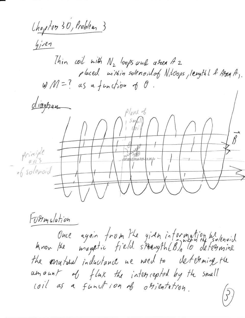
1 Fall 12 PHY 122 Homework Solutions #10 HW10: Ch.30 Q5, 8, 15,17, 19 P 1, 3, 9, 18, 34, 36, 42, 51, 66 Chapter 30 Question 5 If you are given a fixed length of wire, how would you shape it to obtain the greatest self-inductance? The least? Solution To create the greatest self-inductance, bend the wire into as many loops as possible. To create the least self-inductance, leave the wire as a straight piece of wire. Chapter 30 Question 8 At the instant the battery is connected into the LR circuit of Fig. 30 6a, the emf in the inductor has its maximum value even though the current is zero. Explain. Solution Although the current is zero at the instant the battery is connected, the rate at which the current is changing is a maximum and therefore the rate of change of flux through the inductor is a maximum. Since, by Faraday s law, the induced emf depends on the rate of change of flux and not the flux itself, the emf in the inductor is a maximum at this instant. Chapter 30 Question 15 Is it possible for the instantaneous power output of an ac generator connected to an LRC circuit ever to be negative? Explain. Solution Yes. The power output of the generator is P = IV. When either the instantaneous current or the instantaneous voltage in the circuit is negative, and the other variable is positive, the instantaneous power output can be negative. At this time either the inductor or the capacitor is discharging power back to the generator.

2 Chapter 30 Question 17 Describe briefly how the frequency of the source emf affects the impedance of (a) a pure resistance, (b) a pure capacitance, (c) a pure inductance, (d) an LRC circuit near resonance (R small), (e) an LRC circuit far from resonance (R small). Solution (a) The impedance of a pure resistance is unaffected by the frequency of the source emf. (b) The impedance of a pure capacitance decreases with increasing frequency. (c) The impedance of a pure inductance increases with increasing frequency. (d) In an LRC circuit near resonance, small changes in the frequency will cause large changes in the impedance. (e) For frequencies far above the resonance frequency, the impedance of the LRC circuit is dominated by the inductive reactance and will increase with increasing frequency. For frequencies far below the resonance frequency, the impedance of the LRC circuit is dominated by the capacitive reactance and will decrease with increasing frequency. Chapter 30 Question 19 An LRC resonant circuit is often called an oscillator circuit. What is it that oscillates? Solution In an LRC circuit, the current and the voltage in the circuit both oscillate. The energy stored in the circuit also oscillates and is alternately stored in the magnetic field of the inductor and the electric field of the capacitor. Chapter 30 Problem 1 A 2.44-m-long coil containing 225 loops is wound on an iron core (average μ=1850μ 0 ) along with a second coil of 115 loops. The loops of each coil have a radius of 2.00 cm. If the current in the first coil drops uniformly from 12.0 A to zero in 98.0 ms, determine: (a) the mutual inductance M; (b) the emf induced in the second coil. Chapter 30 Problem 3 A small thin coil with N2 loops, each of area A2, is placed inside a long solenoid, near its center. The solenoid has N1 loops in its length l and has area A1. Determine the mutual inductance as a function of θ the angle between the plane of the small coil and the axis of the solenoid.
 In an LRC circuit near resonance, small changes in the frequency will cause large changes in the impedance.")
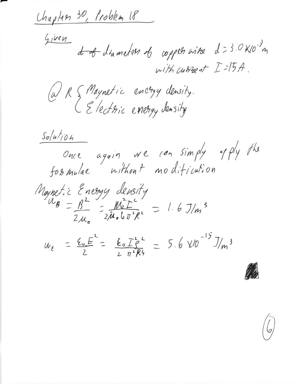
3 Chapter 30 Problem 9 A coil has 3.25Ω resistance and 440-mH inductance. If the current is 3.00 A and is increasing at a rate of 3.60A/s what is the potential difference across the coil at this moment? Chapter 30 Problem 18 Calculate the magnetic and electric energy densities at the surface of a 3.0-mm-diameter copper wire carrying a 15-A current. Chapter 30 Problem 34 A 425-pF capacitor is charged to 135 V and then quickly connected to a 175-mH inductor. Determine (a) the frequency of oscillation, (b) the peak value of the current, and (c) the maximum energy stored in the magnetic field of the inductor.

4

5

6
7

8

9
10

11

Homework #11 203-1-1721 Physics 2 for Students of Mechanical Engineering
 Homework #11 203-1-1721 Physics 2 for Students of Mechanical Engineering 2. A circular coil has a 10.3 cm radius and consists of 34 closely wound turns of wire. An externally produced magnetic field of
45. The peak value of an alternating current in a 1500-W device is 5.4 A. What is the rms voltage across?
 PHYS Practice Problems hapters 8- hapter 8. 45. The peak value of an alternating current in a 5-W device is 5.4 A. What is the rms voltage across? The power and current can be used to find the peak voltage,
104 Practice Exam 2-3/21/02
 104 Practice Exam 2-3/21/02 1. Two electrons are located in a region of space where the magnetic field is zero. Electron A is at rest; and electron B is moving westward with a constant velocity. A non-zero
Circuits with inductors and alternating currents. Chapter 20 #45, 46, 47, 49
 Circuits with inductors and alternating currents Chapter 20 #45, 46, 47, 49 RL circuits Ch. 20 (last section) Symbol for inductor looks like a spring. An inductor is a circuit element that has a large
2. A conductor of length 2m moves at 4m/s at 30 to a uniform magnetic field of 0.1T. Which one of the following gives the e.m.f. generated?
 Extra Questions - 2 1. A straight length of wire moves through a uniform magnetic field. The e.m.f. produced across the ends of the wire will be maximum if it moves: a) along the lines of magnetic flux
12. The current in an inductor is changing at the rate of 100 A/s, and the inductor emf is 40 V. What is its self-inductance?
 12. The current in an inductor is changing at the rate of 100 A/s, and the inductor emf is 40 V. What is its self-inductance? From Equation 32-5, L = -E=(dI =dt) = 40 V=(100 A/s) = 0.4 H. 15. A cardboard
Inductors & Inductance. Electronic Components
 Electronic Components Induction In 1824, Oersted discovered that current passing though a coil created a magnetic field capable of shifting a compass needle. Seven years later, Faraday and Henry discovered
Slide 1 / 26. Inductance. 2011 by Bryan Pflueger
 Slide 1 / 26 Inductance 2011 by Bryan Pflueger Slide 2 / 26 Mutual Inductance If two coils of wire are placed near each other and have a current passing through them, they will each induce an emf on one
Eðlisfræði 2, vor 2007
 [ Assignment View ] [ Print ] Eðlisfræði 2, vor 2007 30. Inductance Assignment is due at 2:00am on Wednesday, March 14, 2007 Credit for problems submitted late will decrease to 0% after the deadline has
Induced voltages and Inductance Faraday s Law
 Induced voltages and Inductance Faraday s Law concept #1, 4, 5, 8, 13 Problem # 1, 3, 4, 5, 6, 9, 10, 13, 15, 24, 23, 25, 31, 32a, 34, 37, 41, 43, 51, 61 Last chapter we saw that a current produces a magnetic
Diodes have an arrow showing the direction of the flow.
 The Big Idea Modern circuitry depends on much more than just resistors and capacitors. The circuits in your computer, cell phone, Ipod depend on circuit elements called diodes, inductors, transistors,
PHYS 222 Spring 2012 Final Exam. Closed books, notes, etc. No electronic device except a calculator.
 PHYS 222 Spring 2012 Final Exam Closed books, notes, etc. No electronic device except a calculator. NAME: (all questions with equal weight) 1. If the distance between two point charges is tripled, the
Phys222 Winter 2012 Quiz 4 Chapters 29-31. Name
 Name If you think that no correct answer is provided, give your answer, state your reasoning briefly; append additional sheet of paper if necessary. 1. A particle (q = 5.0 nc, m = 3.0 µg) moves in a region
Direction of Induced Current
 Direction of Induced Current Bar magnet moves through coil Current induced in coil A S N v Reverse pole Induced current changes sign B N S v v Coil moves past fixed bar magnet Current induced in coil as
MULTIPLE CHOICE. Choose the one alternative that best completes the statement or answers the question.
 MULTIPLE CHOICE. Choose the one alternative that best completes the statement or answers the question. 1) If the voltage at a point in space is zero, then the electric field must be A) zero. B) positive.
Solution Derivations for Capa #11
 Solution Derivations for Capa #11 Caution: The symbol E is used interchangeably for energy and EMF. 1) DATA: V b = 5.0 V, = 155 Ω, L = 8.400 10 2 H. In the diagram above, what is the voltage across the
Chapter 11. Inductors ISU EE. C.Y. Lee
 Chapter 11 Inductors Objectives Describe the basic structure and characteristics of an inductor Discuss various types of inductors Analyze series inductors Analyze parallel inductors Analyze inductive
ElectroMagnetic Induction. AP Physics B
 ElectroMagnetic Induction AP Physics B What is E/M Induction? Electromagnetic Induction is the process of using magnetic fields to produce voltage, and in a complete circuit, a current. Michael Faraday
Physics 2102 Lecture 19. Physics 2102
 Physics 2102 Jonathan Dowling Physics 2102 Lecture 19 Ch 30: Inductors and RL Circuits Nikolai Tesla What are we going to learn? A road map Electric charge Electric force on other electric charges Electric
Measuring Impedance and Frequency Response of Guitar Pickups
 Measuring Impedance and Frequency Response of Guitar Pickups Peter D. Hiscocks Syscomp Electronic Design Limited [email protected] www.syscompdesign.com April 30, 2011 Introduction The CircuitGear
April 1. Physics 272. Spring 2014 http://www.phys.hawaii.edu/~philipvd/pvd_14_spring_272_uhm.html. Prof. Philip von Doetinchem philipvd@hawaii.
 Physics 272 April 1 Spring 2014 http://www.phys.hawaii.edu/~philipvd/pvd_14_spring_272_uhm.html Prof. Philip von Doetinchem [email protected] Phys272 - Spring 14 - von Doetinchem - 164 Summary Gauss's
ε: Voltage output of Signal Generator (also called the Source voltage or Applied
 Experiment #10: LR & RC Circuits Frequency Response EQUIPMENT NEEDED Science Workshop Interface Power Amplifier (2) Voltage Sensor graph paper (optional) (3) Patch Cords Decade resistor, capacitor, and
Inductance. Motors. Generators
 Inductance Motors Generators Self-inductance Self-inductance occurs when the changing flux through a circuit arises from the circuit itself. As the current increases, the magnetic flux through a loop due
Line Reactors and AC Drives
 Line Reactors and AC Drives Rockwell Automation Mequon Wisconsin Quite often, line and load reactors are installed on AC drives without a solid understanding of why or what the positive and negative consequences
An equivalent circuit of a loop antenna.
 3.2.1. Circuit Modeling: Loop Impedance A loop antenna can be represented by a lumped circuit when its dimension is small with respect to a wavelength. In this representation, the circuit parameters (generally
Capacitors in Circuits
 apacitors in ircuits apacitors store energy in the electric field E field created by the stored charge In circuit apacitor may be absorbing energy Thus causes circuit current to be reduced Effectively
Inductors in AC Circuits
 Inductors in AC Circuits Name Section Resistors, inductors, and capacitors all have the effect of modifying the size of the current in an AC circuit and the time at which the current reaches its maximum
Physics 6C, Summer 2006 Homework 2 Solutions
 Physics 6C, Summer 006 Homework Solutions All problems are from the nd edition of Walker. Numerical values are different for each student. Chapter 3 Problems. Figure 3-30 below shows a circuit containing
Last time : energy storage elements capacitor.
 Last time : energy storage elements capacitor. Charge on plates Energy stored in the form of electric field Passive sign convention Vlt Voltage drop across real capacitor can not change abruptly because
Lecture 22. Inductance. Magnetic Field Energy. Outline:
 Lecture 22. Inductance. Magnetic Field Energy. Outline: Self-induction and self-inductance. Inductance of a solenoid. The energy of a magnetic field. Alternative definition of inductance. Mutual Inductance.
Edmund Li. Where is defined as the mutual inductance between and and has the SI units of Henries (H).
.") INDUCTANCE MUTUAL INDUCTANCE If we consider two neighbouring closed loops and with bounding surfaces respectively then a current through will create a magnetic field which will link with as the flux passes
INDUCTANCE MUTUAL INDUCTANCE If we consider two neighbouring closed loops and with bounding surfaces respectively then a current through will create a magnetic field which will link with as the flux passes
Inductors. AC Theory. Module 3
 Module 3 AC Theory What you ll learn in Module 3. Section 3.1 Electromagnetic Induction. Magnetic Fields around Conductors. The Solenoid. Section 3.2 Inductance & Back e.m.f. The Unit of Inductance. Factors
AC Generators. Basic Generator
 AC Generators Basic Generator A basic generator consists of a magnetic field, an armature, slip rings, brushes and a resistive load. The magnetic field is usually an electromagnet. An armature is any number
CHAPTER 30: Inductance, Electromagnetic Oscillations, and AC Circuits
 HAPTE 3: Inductance, Electromagnetic Oscillations, and A ircuits esponses to Questions. (a) For the maximum value of the mutual inductance, place the coils close together, face to face, on the same axis.
DEGREE: Bachelor's Degree in Industrial Electronics and Automation COURSE: 1º TERM: 2º WEEKLY PLANNING
 SESSION WEEK COURSE: Physics II DEGREE: Bachelor's Degree in Industrial Electronics and Automation COURSE: 1º TERM: 2º WEEKLY PLANNING DESCRIPTION GROUPS (mark ) Indicate YES/NO If the session needs 2
Chapter 30 Inductance, Electromagnetic Oscillations, and AC Circuits. Copyright 2009 Pearson Education, Inc.
 Chapter 30 Inductance, Electromagnetic Oscillations, and AC Circuits 30-1 Mutual Inductance Mutual inductance: a changing current in one coil will induce a current in a second coil: Coil 1 produces a flux
RLC Series Resonance
 RLC Series Resonance 11EM Object: The purpose of this laboratory activity is to study resonance in a resistor-inductor-capacitor (RLC) circuit by examining the current through the circuit as a function
 Last Name: First Name: Physics 102 Spring 2006: Exam #2 Multiple-Choice Questions 1. A charged particle, q, is moving with speed v perpendicular to a uniform magnetic field. A second identical charged
Three phase circuits
 Three phase circuits THREE PHASE CIRCUITS THREE-PHASE ADVANTAGES 1. The horsepower rating of three-phase motors and the kva rating of three-phase transformers are 150% greater than single-phase motors
Impedance Matching and Matching Networks. Valentin Todorow, December, 2009
 Impedance Matching and Matching Networks Valentin Todorow, December, 2009 RF for Plasma Processing - Definition of RF What is RF? The IEEE Standard Dictionary of Electrical and Electronics Terms defines
DIRECT CURRENT GENERATORS
 DIRECT CURRENT GENERATORS Revision 12:50 14 Nov 05 INTRODUCTION A generator is a machine that converts mechanical energy into electrical energy by using the principle of magnetic induction. This principle
EDEXCEL NATIONAL CERTIFICATE/DIPLOMA UNIT 5 - ELECTRICAL AND ELECTRONIC PRINCIPLES NQF LEVEL 3 OUTCOME 4 - ALTERNATING CURRENT
 EDEXCEL NATIONAL CERTIFICATE/DIPLOMA UNIT 5 - ELECTRICAL AND ELECTRONIC PRINCIPLES NQF LEVEL 3 OUTCOME 4 - ALTERNATING CURRENT 4 Understand single-phase alternating current (ac) theory Single phase AC
Chapter 30 Inductance
 Chapter 30 Inductance - Mutual Inductance - Self-Inductance and Inductors - Magnetic-Field Energy - The R- Circuit - The -C Circuit - The -R-C Series Circuit . Mutual Inductance - A changing current in
Chapter 12 Driven RLC Circuits
 hapter Driven ircuits. A Sources... -. A ircuits with a Source and One ircuit Element... -3.. Purely esistive oad... -3.. Purely Inductive oad... -6..3 Purely apacitive oad... -8.3 The Series ircuit...
( )( 10!12 ( 0.01) 2 2 = 624 ( ) Exam 1 Solutions. Phy 2049 Fall 2011
( 10!12 ( 0.01) 2 2 = 624 ( ) Exam 1 Solutions. Phy 2049 Fall 2011") Phy 49 Fall 11 Solutions 1. Three charges form an equilateral triangle of side length d = 1 cm. The top charge is q = - 4 μc, while the bottom two are q1 = q = +1 μc. What is the magnitude of the net force
Phy 49 Fall 11 Solutions 1. Three charges form an equilateral triangle of side length d = 1 cm. The top charge is q = - 4 μc, while the bottom two are q1 = q = +1 μc. What is the magnitude of the net force
Application Note. So You Need to Measure Some Inductors?
 So You Need to Measure Some nductors? Take a look at the 1910 nductance Analyzer. Although specifically designed for production testing of inductors and coils, in addition to measuring inductance (L),
Lesson 3 DIRECT AND ALTERNATING CURRENTS. Task. The skills and knowledge taught in this lesson are common to all missile repairer tasks.
 Lesson 3 DIRECT AND ALTERNATING CURRENTS Task. The skills and knowledge taught in this lesson are common to all missile repairer tasks. Objectives. When you have completed this lesson, you should be able
Alternating-Current Circuits
 hapter 1 Alternating-urrent ircuits 1.1 A Sources... 1-1. Simple A circuits... 1-3 1..1 Purely esistive load... 1-3 1.. Purely Inductive oad... 1-5 1..3 Purely apacitive oad... 1-7 1.3 The Series ircuit...
Magnetic Field of a Circular Coil Lab 12
 HB 11-26-07 Magnetic Field of a Circular Coil Lab 12 1 Magnetic Field of a Circular Coil Lab 12 Equipment- coil apparatus, BK Precision 2120B oscilloscope, Fluke multimeter, Wavetek FG3C function generator,
W03 Analysis of DC Circuits. Yrd. Doç. Dr. Aytaç Gören
 W03 Analysis of DC Circuits Yrd. Doç. Dr. Aytaç Gören ELK 2018 - Contents W01 Basic Concepts in Electronics W02 AC to DC Conversion W03 Analysis of DC Circuits (self and condenser) W04 Transistors and
ES250: Electrical Science. HW7: Energy Storage Elements
 ES250: Electrical Science HW7: Energy Storage Elements Introduction This chapter introduces two more circuit elements, the capacitor and the inductor whose elements laws involve integration or differentiation;
Objectives. Capacitors 262 CHAPTER 5 ENERGY
 Objectives Describe a capacitor. Explain how a capacitor stores energy. Define capacitance. Calculate the electrical energy stored in a capacitor. Describe an inductor. Explain how an inductor stores energy.
DOE FUNDAMENTALS HANDBOOK ELECTRICAL SCIENCE Volume 3 of 4
 DOE-HDBK-1011/3-92 JUNE 1992 DOE FUNDAMENTALS HANDBOOK ELECTRICAL SCIENCE Volume 3 of 4 U.S. Department of Energy Washington, D.C. 20585 FSC-6910 Distribution Statement A. Approved for public release;
Experiment 8: Undriven & Driven RLC Circuits
 Experiment 8: Undriven & Driven RLC Circuits Answer these questions on a separate sheet of paper and turn them in before the lab 1. RLC Circuits Consider the circuit at left, consisting of an AC function
Chapter 35 Alternating Current Circuits
 hapter 35 Alternating urrent ircuits ac-ircuits Phasor Diagrams Resistors, apacitors and nductors in ac-ircuits R ac-ircuits ac-ircuit power. Resonance Transformers ac ircuits Alternating currents and
Physics 121 Sample Common Exam 3 NOTE: ANSWERS ARE ON PAGE 6. Instructions: 1. In the formula F = qvxb:
 Physics 121 Sample Common Exam 3 NOTE: ANSWERS ARE ON PAGE 6 Signature Name (Print): 4 Digit ID: Section: Instructions: Answer all questions 24 multiple choice questions. You may need to do some calculation.
RUPHYS2272015 ( RUPHY227F2015 ) My Courses Course Settings University Physics with Modern Physics, 14e Young/Freedman
 My Courses Course Settings University Physics with Modern Physics, 14e Young/Freedman") Signed in as Jolie Cizewski, Instructor Help Sign Out RUPHYS2272015 ( RUPHY227F2015 ) My Courses Course Settings University Physics with Modern Physics, 14e Young/Freedman Course Home Assignments Roster
Signed in as Jolie Cizewski, Instructor Help Sign Out RUPHYS2272015 ( RUPHY227F2015 ) My Courses Course Settings University Physics with Modern Physics, 14e Young/Freedman Course Home Assignments Roster
Candidate Number. General Certificate of Education Advanced Level Examination June 2014
 entre Number andidate Number Surname Other Names andidate Signature General ertificate of Education dvanced Level Examination June 214 Physics PHY4/1 Unit 4 Fields and Further Mechanics Section Wednesday
Candidate Number. General Certificate of Education Advanced Level Examination June 2012
 entre Number andidate Number Surname Other Names andidate Signature General ertificate of Education dvanced Level Examination June 212 Physics PHY4/1 Unit 4 Fields and Further Mechanics Section Monday
Iron Powder Cores for Switchmode Power Supply Inductors. by: Jim Cox
 HOME APPLICATION NOTES Iron Powder Cores for Switchmode Power Supply Inductors by: Jim Cox Purpose: The purpose of this application note is to cover the properties of iron powder as a magnetic core material
BASIC ELECTRONICS AC CIRCUIT ANALYSIS. December 2011
 AM 5-202 BASIC ELECTRONICS AC CIRCUIT ANALYSIS December 2011 DISTRIBUTION RESTRICTION: Approved for Pubic Release. Distribution is unlimited. DEPARTMENT OF THE ARMY MILITARY AUXILIARY RADIO SYSTEM FORT
potential in the centre of the sphere with respect to infinity.
 Umeå Universitet, Fysik 1 Vitaly Bychkov Prov i fysik, Electricity and Waves, 2006-09-27, kl 16.00-22.00 Hjälpmedel: Students can use any book. Define the notations you are using properly. Present your
Physics 25 Exam 3 November 3, 2009
 1. A long, straight wire carries a current I. If the magnetic field at a distance d from the wire has magnitude B, what would be the the magnitude of the magnetic field at a distance d/3 from the wire,
THE LUCAS C40 DYNAMO & ITS ARMATURE.
 THE LUCAS C40 DYNAMO & ITS ARMATURE. H. Holden, March 2011. The Dynamo as a DC generating machine was used extensively in the pre- Alternator era, from the early 1900 s up to the late 1960 s and early
Alternating Current Circuits and Electromagnetic Waves
 Arecibo, a large radio telescope in Puerto Rico, gathers electromagnetic radiation in the form of radio waves. These long wavelengths pass through obscuring dust clouds, allowing astronomers to create
Experiment #11: LRC Circuit (Power Amplifier, Voltage Sensor)
") Experiment #11: LRC Circuit (Power Amplifier, Voltage Sensor) Concept: circuits Time: 30 m SW Interface: 750 Windows file: RLC.SWS EQUIPMENT NEEDED Science Workshop Interface Power Amplifier (2) Voltage
Experiment #11: LRC Circuit (Power Amplifier, Voltage Sensor) Concept: circuits Time: 30 m SW Interface: 750 Windows file: RLC.SWS EQUIPMENT NEEDED Science Workshop Interface Power Amplifier (2) Voltage
The purposes of this experiment are to test Faraday's Law qualitatively and to test Lenz's Law.
 260 17-1 I. THEORY EXPERIMENT 17 QUALITATIVE STUDY OF INDUCED EMF Along the extended central axis of a bar magnet, the magnetic field vector B r, on the side nearer the North pole, points away from this
Candidate Number. General Certificate of Education Advanced Level Examination June 2010
 entre Number andidate Number Surname Other Names andidate Signature General ertificate of Education dvanced Level Examination June 1 Physics PHY4/1 Unit 4 Fields and Further Mechanics Section Friday 18
DC GENERATOR THEORY. LIST the three conditions necessary to induce a voltage into a conductor.
 DC Generators DC generators are widely used to produce a DC voltage. The amount of voltage produced depends on a variety of factors. EO 1.5 LIST the three conditions necessary to induce a voltage into
PHY114 S11 Term Exam 3
 PHY4 S Term Exam S. G. Rajeev Mar 2 20 2:0 pm to :45 pm PLEASE write your workshop number and your workshop leader s name at the top of your book, so that you can collect your graded exams at the workshop.
A METHOD OF CALIBRATING HELMHOLTZ COILS FOR THE MEASUREMENT OF PERMANENT MAGNETS
 A METHOD OF CALIBRATING HELMHOLTZ COILS FOR THE MEASUREMENT OF PERMANENT MAGNETS Joseph J. Stupak Jr, Oersted Technology Tualatin, Oregon (reprinted from IMCSD 24th Annual Proceedings 1995) ABSTRACT The
Power Quality Paper #3
 The Effect of Voltage Dips On Induction Motors by: M D McCulloch 1. INTRODUCTION Voltage depressions caused by faults on the system affect the performance of induction motors, in terms of the production
Reading assignment: All students should read the Appendix about using oscilloscopes.
 10. A ircuits* Objective: To learn how to analyze current and voltage relationships in alternating current (a.c.) circuits. You will use the method of phasors, or the vector addition of rotating vectors
RLC Resonant Circuits
 C esonant Circuits Andrew McHutchon April 20, 203 Capacitors and Inductors There is a lot of inconsistency when it comes to dealing with reactances of complex components. The format followed in this document
How To Understand And Understand The Theory Of Electricity
 DIRECT CURRENT AND ALTERNATING CURRENT SYSTEMS N. Rajkumar, Research Fellow, Energy Systems Group, City University Northampton Square, London EC1V 0HB, UK Keywords: Electrical energy, direct current, alternating
1. The diagram below represents magnetic lines of force within a region of space.
 1. The diagram below represents magnetic lines of force within a region of space. 4. In which diagram below is the magnetic flux density at point P greatest? (1) (3) (2) (4) The magnetic field is strongest
EE301 Lesson 14 Reading: 10.1-10.4, 10.11-10.12, 11.1-11.4 and 11.11-11.13
 CAPACITORS AND INDUCTORS Learning Objectives EE301 Lesson 14 a. Define capacitance and state its symbol and unit of measurement. b. Predict the capacitance of a parallel plate capacitor. c. Analyze how
Basic Electrical Technology Dr. L. Umanand Department of Electrical Engineering Indian Institute of Science, Bangalore. Lecture - 33 3 phase System 4
 Basic Electrical Technology Dr. L. Umanand Department of Electrical Engineering Indian Institute of Science, Bangalore Lecture - 33 3 phase System 4 Hello everybody. So, in the last class we have been
Lecture 24. Inductance and Switching Power Supplies (how your solar charger voltage converter works)
") Lecture 24 Inductance and Switching Power Supplies (how your solar charger voltage converter works) Copyright 2014 by Mark Horowitz 1 Roadmap: How Does This Work? 2 Processor Board 3 More Detailed Roadmap
Lecture 24 Inductance and Switching Power Supplies (how your solar charger voltage converter works) Copyright 2014 by Mark Horowitz 1 Roadmap: How Does This Work? 2 Processor Board 3 More Detailed Roadmap
Aircraft Electrical System
 Chapter 9 Aircraft Electrical System Introduction The satisfactory performance of any modern aircraft depends to a very great degree on the continuing reliability of electrical systems and subsystems.
TEACHER S CLUB EXAMS GRADE 11. PHYSICAL SCIENCES: PHYSICS Paper 1
 TEACHER S CLUB EXAMS GRADE 11 PHYSICAL SCIENCES: PHYSICS Paper 1 MARKS: 150 TIME: 3 hours INSTRUCTIONS AND INFORMATION 1. This question paper consists of 12 pages, two data sheets and a sheet of graph
5. Measurement of a magnetic field
 H 5. Measurement of a magnetic field 5.1 Introduction Magnetic fields play an important role in physics and engineering. In this experiment, three different methods are examined for the measurement of
REPORT ON CANDIDATES WORK IN THE CARIBBEAN ADVANCED PROFICIENCY EXAMINATION MAY/JUNE 2008 ELECTRICAL AND ELECTRONIC TECHNOLOGY (TRINIDAD AND TOBAGO)
") CARIBBEAN EXAMINATIONS COUNCIL REPORT ON CANDIDATES WORK IN THE CARIBBEAN ADVANCED PROFICIENCY EXAMINATION MAY/JUNE 2008 ELECTRICAL AND ELECTRONIC TECHNOLOGY (TRINIDAD AND TOBAGO) Copyright 2008 Caribbean
CARIBBEAN EXAMINATIONS COUNCIL REPORT ON CANDIDATES WORK IN THE CARIBBEAN ADVANCED PROFICIENCY EXAMINATION MAY/JUNE 2008 ELECTRICAL AND ELECTRONIC TECHNOLOGY (TRINIDAD AND TOBAGO) Copyright 2008 Caribbean
Magnetism. d. gives the direction of the force on a charge moving in a magnetic field. b. results in negative charges moving. clockwise.
 Magnetism 1. An electron which moves with a speed of 3.0 10 4 m/s parallel to a uniform magnetic field of 0.40 T experiences a force of what magnitude? (e = 1.6 10 19 C) a. 4.8 10 14 N c. 2.2 10 24 N b.
Chapter 22: Electric motors and electromagnetic induction
 Chapter 22: Electric motors and electromagnetic induction The motor effect movement from electricity When a current is passed through a wire placed in a magnetic field a force is produced which acts on
Single Transistor FM Transmitter Design
 Single Transistor FM Transmitter Design In telecommunications, frequency modulation (FM) conveys information over a carrier wave by varying its frequency. FM is commonly used at VHF radio frequencies for
Module Title: Electrotechnology for Mech L7
 CORK INSTITUTE OF TECHNOLOGY INSTITIÚID TEICNEOLAÍOCHTA CHORCAÍ Autumn Examinations 2012 Module Title: Electrotechnology for Mech L7 Module Code: ELEC7007 School: School of Mechanical, Electrical and Process
Review Questions PHYS 2426 Exam 2
 Review Questions PHYS 2426 Exam 2 1. If 4.7 x 10 16 electrons pass a particular point in a wire every second, what is the current in the wire? A) 4.7 ma B) 7.5 A C) 2.9 A D) 7.5 ma E) 0.29 A Ans: D 2.
Chapter 25 Alternating Currents
 Physics Including Human Applications 554 Chapter 25 Alternating Currents GOALS When you have mastered the contents of this chapter, you will be able to achieve the following goals: Definitions Define each
Sinusoidal. Oscillators
 364 4 Principles of Electronics Sinusoidal Oscillators 4. Sinusoidal Oscillator 4.2 Types of Sinusoidal Oscillations 4.3 Oscillatory Circuit 4.4 Undamped Oscillations from Tank Circuit 4.5 Positive Feedback
LR Phono Preamps. Pete Millett ETF.13. [email protected]
 LR Phono Preamps Pete Millett ETF.13 [email protected] Agenda A bit about me Part 1: What is, and why use, RIAA? Grooves on records The RIAA standard Implementations of RIAA EQ networks and preamps
CURRENT ELECTRICITY INTRODUCTION TO RESISTANCE, CAPACITANCE AND INDUCTANCE
 CURRENT ELECTRICITY INTRODUCTION TO RESI STANCE, CAPACITANCE AND INDUCTANCE P R E A M B L E This problem is adapted from an on-line knowledge enhancement module for a PGCE programme. It is used to cover
Fundamentals of Signature Analysis
 Fundamentals of Signature Analysis An In-depth Overview of Power-off Testing Using Analog Signature Analysis www.huntron.com 1 www.huntron.com 2 Table of Contents SECTION 1. INTRODUCTION... 7 PURPOSE...
Physics 102: Lecture 13 RLC circuits & Resonance
 Physics 102: Lecture 13 L circuits & esonance L Physics 102: Lecture 13, Slide 1 I = I max sin(2pft) V = I max sin(2pft) V in phase with I eview: A ircuit L V = I max X sin(2pft p/2) V lags I IE I V t
EE 221 Circuits II. Chapter 13 Magnetically Coupled Circuits
 EE Circuits II Chapter 3 Magnetically Coupled Circuits Magnetically Coupled Circuits 3. What is a transformer? 3. Mutual Inductance 3.3 Energy in a Coupled Circuit 3.4 inear Transformers 3.5 Ideal Transformers
Equipment: Power Supply, DAI, Synchronous motor (8241), Electrodynamometer (8960), Tachometer, Timing belt.
, Electrodynamometer (8960), Tachometer, Timing belt.") Lab 9: Synchronous motor. Objective: to examine the design of a 3-phase synchronous motor; to learn how to connect it; to obtain its starting characteristic; to determine the full-load characteristic of
Lab 9: Synchronous motor. Objective: to examine the design of a 3-phase synchronous motor; to learn how to connect it; to obtain its starting characteristic; to determine the full-load characteristic of
Science and Reactor Fundamentals Electrical CNSC Technical Training Group. Table of Contents
 Electrical Science and Reactor Fundamentals Electrical i Table of Contents 1 Objectives... 1 1.1 BASIC ELECTRICAL THEORY... 1 1.2 TRANSFORMERS... 1 1.3 GENERATORS... 2 1.4 PROTECTION... 3 2 BASIC ELECTRICAL
Introduction to the Smith Chart for the MSA Sam Wetterlin 10/12/09 Z +
 Introduction to the Smith Chart for the MSA Sam Wetterlin 10/12/09 Quick Review of Reflection Coefficient The Smith chart is a method of graphing reflection coefficients and impedance, and is often useful