Chapter 30 Inductance
|
|
|
- Nancy Stewart
- 8 years ago
- Views:
Transcription
1 Chapter 30 Inductance - Mutual Inductance - Self-Inductance and Inductors - Magnetic-Field Energy - The R- Circuit - The -C Circuit - The -R-C Series Circuit

2 . Mutual Inductance - A changing current in coil causes B and a changing magnetic flux through coil that induces emf in coil. ε N dφ B Magnetic flux through coil : N B M Φ i Mutual inductance of two coils: M ε dφ B N M M M N Φ i B M is a constant that depends on geometry of the coils M.

3 - If a magnetic material is present, M will depend on magnetic properties. If relative permeability (K m ) is not constant (M not proportional to B) Φ B not proportional to i (exception). ε ε M M Mutual inductance: emf opposes the flux change M N Φ i B NΦ i B - Only a time-varying current induces an emf. Units of inductance: Henry Weber/A V s/a J/A Ex. 30.

4 . Self Inductance and Inductors - When a current is present in a circuit, it sets up B that causes a magnetic flux that changes when the current changes emf is induced. enz s law: a self-induced emf opposes the change in current that caused it Induced emf makes fficult variations in current. NΦ i B Self-inductance dφ N B ε Self-induced emf

5 Inductors as Circuit Elements Inductors oppose variations in the current through a circuit. -In DC-circuit, helps to maintain a steady current (despite fluctuations in applied emf). In AC circuit, helps to suppress fast variations in current. - Reminder of Kirchhoff s loop rule: the sum of potential fferences around any closed loop is zero because E produced by charges stributed around circuit is conservative E c. -The magnetically induced electric field within the coils of an inductor is nonconservative (E n ). - If R 0 in inductor s coils very small E required to move charge through coils total E through coils E c + E n 0. Since E c 0 E c -E n accumulation of charge on inductor s terminals and surfaces of its conductors to produce that field. E n dl
.")
6 - E n 0 only within the inductor. b a b a E E n c dl dl E c E + n 0 (at each point within the inductor s coil) - Self-induced emf opposes changes in current. Potential fference between terminals of an inductor: Vab Va Vb V ab is associated with conservative, electrostatic forces, despite the fact that E associated with the magnetic induction is non-conservative Kirchhoff s loop rule can be used. - If magnetic flux is concentrated in region with a magnetic material µ 0 in eqs. must be replaced by µ K m µ 0.

7

8 3. Magnetic-Field Energy - Establishing a current in an inductor requires an input of energy. An inductor carrying a current has energy stored in it. Energy Stored in an Inductor Rate of transfer of energy into : P Vabi i Energy supplied to inductor during : du P i Total energy U supplied while the current increases from zero to I: U I i 0 I Energy stored in an inductor - Energy flows into an ideal (R 0) inductor when current in inductor increases. The energy is not ssipated, but stored in and released when current decreases.
")
9 Magnetic Energy Density r A N π µ 0 0 ) ( r I N A r U V U u π µ π 0 I r A N I U π µ -The energy in an inductor is stored in the magnetic field within the coil, just as the energy of a capacitor is stored in the electric field between its plates. Ex: toroidal solenoid (B confined to a finite region of space within its core). V (πr) A Energy per unit volume: u U/V magnetic energy density
.")
10 µ µ 0 B u B u ( ) 0 µ π B r I N r NI B π µ 0 Magnetic energy density in vacuum Magnetic energy density in a material

11 4. The R- Circuit - An inductor in a circuit makes it fficult for rapid changes in current to occur due to induced emf. Current-Growth in an R- Circuit At t 0 Switch closed. v ab I R v bc ε i R 0 ε ir ε R i

12 initial final ε 0 ε R I ( t 0 i 0 V ab 0) ε I R ( t f / 0) i ε R ( ) R i ' i' ( ε ) R t 0 0 i ln ( ε R) ε R R ' R Current in R- circuit: t ε i e R ( R ) t
")
13 ε e ( R )t t 0 i 0, / ε / t i ε/r, / 0 Time constant for an R- circuit: τ R At t τ, the current has risen to (-/e) (63 % ) of its final value. Power supplied by the source: ε i i R Power ssipated by R + i Power stored in inductor

14 Current-Decay in an R- Circuit i I 0 e ( R )t t 0 I 0 Τ /R for current to decrease to /e (37 % of I 0 ). Total energy in circuit: 0 i R + i No energy supplied by a source (no battery present)

15 5. The -C Circuit - In -C circuit, the charge on the capacitor and current through inductor vary sinusoidally with time. Energy is transferred between magnetic energy in inductor (U B ) and electric energy in capacitor (U E ). As in simple harmonic motion, total energy remains constant.
.")
16 -C Circuit t 0 C charged Q C V m C scharges through inductor. Because of induced emf in, the current does not change instantaneously. I starts at 0 until it reaches I m. During C scharge, the potential in C induced emf in. When potential in C 0 induced emf 0 maximum I m. During the scharge of C, the growing current in leads to magnetic field energy stored in C (in its electric field) becomes stored in (in magnetic field). After C fully scharged, some i persists (cannot change instantaneously), C charges with contrary polarity to initial state. As current decreases B decreases induced emf in same rection as current that slows decrease in current. At some point, B 0, i 0 and C fully charged with V m (-Q on left plate, contrary to initial state). If no energy loses, the charges in C oscillate back and forth infinitely electrical oscillation. Energy is transferred from capacitor E to inductor B.
, C charges with contrary polarity to initial state.")
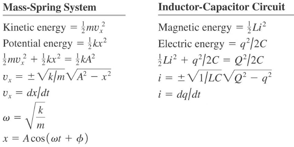
17 Electrical Oscillations in an -C Circuit Shown is + i dq/ (rate of change of q in left plate). If C scharges dq/<0 counter clockwise i is negative. Kirchhoff s loop rule: d q x + q C 0 Acos( ω t + ϕ) -C circuit q C Analogy to eq. for harmonic oscillator: 0 d x k + x m 0 q Q cos t ( ω +ϕ) dq i ω Qsin( ωt + ϕ) ω C Angular frequency of oscillation ω π f If at t 0 Q max in C, i 0 φ 0 If at t 0, q0 φ ±π/ rad
 dq i ω Qsin( ωt + ϕ) ω C Angular frequency")
18 Energy in an -C Circuit Analogy with harmonic oscillator (mass attached to spring): E total 0.5 k A KE + U elas 0.5 m v x k x (A oscillation amplitude) v x ± k m A x Mechanical oscillations - For -C Circuit: Q C i + q C Total energy initially stored in C energy stored in + energy stored in C (at given t). i ± C Q q Electrical oscillations

19
20 6. The -R-C Series Circuit Because of R, the electromagnetic energy of system is ssipated and converted to other forms of energy (e.g. internal energy of circuit materials). [Analogous to friction in mechanical system]. - Energy loses in R i R U B in when C completely scharged < U E Q /C - Small R circuit still oscillates but with damped harmonic motion circuit underdamped. - arge R no oscillations (e out) critically damped. - Very large R circuit overdamped C charge approaches 0 slowly.
 critically damped.")
21 Analyzing an -R-C Circuit ir q C 0 (i dq/) d q R dq + + q C 0 For R < 4/C: (underdamped) q Ae ( R / ) t cos C R 4 t + ϕ A, φ are constants ω ' C R 4 underdamped -R-C series circuit
22 Inductors in series: eq + Inductors in parallel: / eq / + /
Slide 1 / 26. Inductance. 2011 by Bryan Pflueger
 Slide 1 / 26 Inductance 2011 by Bryan Pflueger Slide 2 / 26 Mutual Inductance If two coils of wire are placed near each other and have a current passing through them, they will each induce an emf on one
April 1. Physics 272. Spring 2014 http://www.phys.hawaii.edu/~philipvd/pvd_14_spring_272_uhm.html. Prof. Philip von Doetinchem philipvd@hawaii.
 Physics 272 April 1 Spring 2014 http://www.phys.hawaii.edu/~philipvd/pvd_14_spring_272_uhm.html Prof. Philip von Doetinchem philipvd@hawaii.edu Phys272 - Spring 14 - von Doetinchem - 164 Summary Gauss's
Inductance and Magnetic Energy
 Chapter 11 Inductance and Magnetic Energy 11.1 Mutual Inductance... 11-3 Example 11.1 Mutual Inductance of Two Concentric Coplanar Loops... 11-5 11. Self-Inductance... 11-5 Example 11. Self-Inductance
Eðlisfræði 2, vor 2007
 [ Assignment View ] [ Print ] Eðlisfræði 2, vor 2007 30. Inductance Assignment is due at 2:00am on Wednesday, March 14, 2007 Credit for problems submitted late will decrease to 0% after the deadline has
Induced voltages and Inductance Faraday s Law
 Induced voltages and Inductance Faraday s Law concept #1, 4, 5, 8, 13 Problem # 1, 3, 4, 5, 6, 9, 10, 13, 15, 24, 23, 25, 31, 32a, 34, 37, 41, 43, 51, 61 Last chapter we saw that a current produces a magnetic
Last time : energy storage elements capacitor.
 Last time : energy storage elements capacitor. Charge on plates Energy stored in the form of electric field Passive sign convention Vlt Voltage drop across real capacitor can not change abruptly because
Inductance. Motors. Generators
 Inductance Motors Generators Self-inductance Self-inductance occurs when the changing flux through a circuit arises from the circuit itself. As the current increases, the magnetic flux through a loop due
Homework #11 203-1-1721 Physics 2 for Students of Mechanical Engineering
 Homework #11 203-1-1721 Physics 2 for Students of Mechanical Engineering 2. A circular coil has a 10.3 cm radius and consists of 34 closely wound turns of wire. An externally produced magnetic field of
Lecture 22. Inductance. Magnetic Field Energy. Outline:
 Lecture 22. Inductance. Magnetic Field Energy. Outline: Self-induction and self-inductance. Inductance of a solenoid. The energy of a magnetic field. Alternative definition of inductance. Mutual Inductance.
Solution Derivations for Capa #11
 Solution Derivations for Capa #11 Caution: The symbol E is used interchangeably for energy and EMF. 1) DATA: V b = 5.0 V, = 155 Ω, L = 8.400 10 2 H. In the diagram above, what is the voltage across the
CHAPTER 30: Inductance, Electromagnetic Oscillations, and AC Circuits
 HAPTE 3: Inductance, Electromagnetic Oscillations, and A ircuits esponses to Questions. (a) For the maximum value of the mutual inductance, place the coils close together, face to face, on the same axis.
Objectives. Capacitors 262 CHAPTER 5 ENERGY
 Objectives Describe a capacitor. Explain how a capacitor stores energy. Define capacitance. Calculate the electrical energy stored in a capacitor. Describe an inductor. Explain how an inductor stores energy.
Edmund Li. Where is defined as the mutual inductance between and and has the SI units of Henries (H).
.") INDUCTANCE MUTUAL INDUCTANCE If we consider two neighbouring closed loops and with bounding surfaces respectively then a current through will create a magnetic field which will link with as the flux passes
INDUCTANCE MUTUAL INDUCTANCE If we consider two neighbouring closed loops and with bounding surfaces respectively then a current through will create a magnetic field which will link with as the flux passes
Circuits with inductors and alternating currents. Chapter 20 #45, 46, 47, 49
 Circuits with inductors and alternating currents Chapter 20 #45, 46, 47, 49 RL circuits Ch. 20 (last section) Symbol for inductor looks like a spring. An inductor is a circuit element that has a large
Physics 2102 Lecture 19. Physics 2102
 Physics 2102 Jonathan Dowling Physics 2102 Lecture 19 Ch 30: Inductors and RL Circuits Nikolai Tesla What are we going to learn? A road map Electric charge Electric force on other electric charges Electric
EE301 Lesson 14 Reading: 10.1-10.4, 10.11-10.12, 11.1-11.4 and 11.11-11.13
 CAPACITORS AND INDUCTORS Learning Objectives EE301 Lesson 14 a. Define capacitance and state its symbol and unit of measurement. b. Predict the capacitance of a parallel plate capacitor. c. Analyze how
EEE1001/PHY1002. Magnetic Circuits. The circuit is of length l=2πr. B andφ circulate
 1 Magnetic Circuits Just as we view electric circuits as related to the flow of charge, we can also view magnetic flux flowing around a magnetic circuit. The sum of fluxes entering a point must sum to
Module 22: Inductance and Magnetic Field Energy
 Module 22: Inductance and Magnetic Field Energy 1 Module 22: Outline Self Inductance Energy in Inductors Circuits with Inductors: RL Circuit 2 Faraday s Law of Induction dφ = B dt Changing magnetic flux
Your Comments. This was a very confusing prelecture. Do you think you could go over thoroughly how the LC circuits work qualitatively?
 Your omments I am not feeling great about this mierm...some of this stuff is really confusing still and I don't know if I can shove everything into my brain in time, especially after spring break. an you
W03 Analysis of DC Circuits. Yrd. Doç. Dr. Aytaç Gören
 W03 Analysis of DC Circuits Yrd. Doç. Dr. Aytaç Gören ELK 2018 - Contents W01 Basic Concepts in Electronics W02 AC to DC Conversion W03 Analysis of DC Circuits (self and condenser) W04 Transistors and
Direction of Induced Current
 Direction of Induced Current Bar magnet moves through coil Current induced in coil A S N v Reverse pole Induced current changes sign B N S v v Coil moves past fixed bar magnet Current induced in coil as
DEGREE: Bachelor's Degree in Industrial Electronics and Automation COURSE: 1º TERM: 2º WEEKLY PLANNING
 SESSION WEEK COURSE: Physics II DEGREE: Bachelor's Degree in Industrial Electronics and Automation COURSE: 1º TERM: 2º WEEKLY PLANNING DESCRIPTION GROUPS (mark ) Indicate YES/NO If the session needs 2
Inductors & Inductance. Electronic Components
 Electronic Components Induction In 1824, Oersted discovered that current passing though a coil created a magnetic field capable of shifting a compass needle. Seven years later, Faraday and Henry discovered
Outline. Systems and Signals 214 / 244 & Energy Systems 244 / 344. Ideal Inductor. Ideal Inductor (cont... )
") Outline Systems and Signals 214 / 244 & Energy Systems 244 / 344 Inductance, Leakage Inductance, Mutual Inductance & Transformers 1 Inductor revision Ideal Inductor Non-Ideal Inductor Dr. P.J. Randewijk
Outline Systems and Signals 214 / 244 & Energy Systems 244 / 344 Inductance, Leakage Inductance, Mutual Inductance & Transformers 1 Inductor revision Ideal Inductor Non-Ideal Inductor Dr. P.J. Randewijk
Magnetic Circuits. Outline. Ampere s Law Revisited Review of Last Time: Magnetic Materials Magnetic Circuits Examples
 Magnetic Circuits Outline Ampere s Law Revisited Review of Last Time: Magnetic Materials Magnetic Circuits Examples 1 Electric Fields Magnetic Fields S ɛ o E da = ρdv B V = Q enclosed S da =0 GAUSS GAUSS
Chapter 30 Inductance, Electromagnetic Oscillations, and AC Circuits. Copyright 2009 Pearson Education, Inc.
 Chapter 30 Inductance, Electromagnetic Oscillations, and AC Circuits 30-1 Mutual Inductance Mutual inductance: a changing current in one coil will induce a current in a second coil: Coil 1 produces a flux
ES250: Electrical Science. HW7: Energy Storage Elements
 ES250: Electrical Science HW7: Energy Storage Elements Introduction This chapter introduces two more circuit elements, the capacitor and the inductor whose elements laws involve integration or differentiation;
Physics 6C, Summer 2006 Homework 2 Solutions
 Physics 6C, Summer 006 Homework Solutions All problems are from the nd edition of Walker. Numerical values are different for each student. Chapter 3 Problems. Figure 3-30 below shows a circuit containing
Chapter 11. Inductors ISU EE. C.Y. Lee
 Chapter 11 Inductors Objectives Describe the basic structure and characteristics of an inductor Discuss various types of inductors Analyze series inductors Analyze parallel inductors Analyze inductive
Applications of Second-Order Differential Equations
 Applications of Second-Order Differential Equations Second-order linear differential equations have a variety of applications in science and engineering. In this section we explore two of them: the vibration
12. The current in an inductor is changing at the rate of 100 A/s, and the inductor emf is 40 V. What is its self-inductance?
 12. The current in an inductor is changing at the rate of 100 A/s, and the inductor emf is 40 V. What is its self-inductance? From Equation 32-5, L = -E=(dI =dt) = 40 V=(100 A/s) = 0.4 H. 15. A cardboard
Inductors. AC Theory. Module 3
 Module 3 AC Theory What you ll learn in Module 3. Section 3.1 Electromagnetic Induction. Magnetic Fields around Conductors. The Solenoid. Section 3.2 Inductance & Back e.m.f. The Unit of Inductance. Factors
PHY114 S11 Term Exam 3
 PHY4 S Term Exam S. G. Rajeev Mar 2 20 2:0 pm to :45 pm PLEASE write your workshop number and your workshop leader s name at the top of your book, so that you can collect your graded exams at the workshop.
How To Understand And Understand The Theory Of Electricity
 DIRECT CURRENT AND ALTERNATING CURRENT SYSTEMS N. Rajkumar, Research Fellow, Energy Systems Group, City University Northampton Square, London EC1V 0HB, UK Keywords: Electrical energy, direct current, alternating
Candidate Number. General Certificate of Education Advanced Level Examination June 2014
 entre Number andidate Number Surname Other Names andidate Signature General ertificate of Education dvanced Level Examination June 214 Physics PHY4/1 Unit 4 Fields and Further Mechanics Section Wednesday
RUPHYS2272015 ( RUPHY227F2015 ) My Courses Course Settings University Physics with Modern Physics, 14e Young/Freedman
 My Courses Course Settings University Physics with Modern Physics, 14e Young/Freedman") Signed in as Jolie Cizewski, Instructor Help Sign Out RUPHYS2272015 ( RUPHY227F2015 ) My Courses Course Settings University Physics with Modern Physics, 14e Young/Freedman Course Home Assignments Roster
Signed in as Jolie Cizewski, Instructor Help Sign Out RUPHYS2272015 ( RUPHY227F2015 ) My Courses Course Settings University Physics with Modern Physics, 14e Young/Freedman Course Home Assignments Roster
Magnetic Field of a Circular Coil Lab 12
 HB 11-26-07 Magnetic Field of a Circular Coil Lab 12 1 Magnetic Field of a Circular Coil Lab 12 Equipment- coil apparatus, BK Precision 2120B oscilloscope, Fluke multimeter, Wavetek FG3C function generator,
CHAPTER - 1. Chapter ONE: WAVES CHAPTER - 2. Chapter TWO: RAY OPTICS AND OPTICAL INSTRUMENTS. CHAPTER - 3 Chapter THREE: WAVE OPTICS PERIODS PERIODS
 BOARD OF INTERMEDIATE EDUCATION, A.P., HYDERABAD REVISION OF SYLLABUS Subject PHYSICS-II (w.e.f 2013-14) Chapter ONE: WAVES CHAPTER - 1 1.1 INTRODUCTION 1.2 Transverse and longitudinal waves 1.3 Displacement
45. The peak value of an alternating current in a 1500-W device is 5.4 A. What is the rms voltage across?
 PHYS Practice Problems hapters 8- hapter 8. 45. The peak value of an alternating current in a 5-W device is 5.4 A. What is the rms voltage across? The power and current can be used to find the peak voltage,
Physics 9e/Cutnell. correlated to the. College Board AP Physics 1 Course Objectives
 Physics 9e/Cutnell correlated to the College Board AP Physics 1 Course Objectives Big Idea 1: Objects and systems have properties such as mass and charge. Systems may have internal structure. Enduring
Chapter 35 Alternating Current Circuits
 hapter 35 Alternating urrent ircuits ac-ircuits Phasor Diagrams Resistors, apacitors and nductors in ac-ircuits R ac-ircuits ac-ircuit power. Resonance Transformers ac ircuits Alternating currents and
Coupled Inductors. Introducing Coupled Inductors
 Coupled Inductors From power distribution across large distances to radio transmissions, coupled inductors are used extensively in electrical applications. Their properties allow for increasing or decreasing
Problem Solving 8: RC and LR Circuits
 MASSACHUSETTS INSTITUTE OF TECHNOLOGY Department of Physics Problem Solving 8: RC and LR Circuits Section Table and Group (e.g. L04 3C ) Names Hand in one copy per group at the end of the Friday Problem
Let s examine the response of the circuit shown on Figure 1. The form of the source voltage Vs is shown on Figure 2. R. Figure 1.
 Examples of Transient and RL Circuits. The Series RLC Circuit Impulse response of Circuit. Let s examine the response of the circuit shown on Figure 1. The form of the source voltage Vs is shown on Figure.
Chapter 7 Direct-Current Circuits
 Chapter 7 Direct-Current Circuits 7. Introduction...7-7. Electromotive Force...7-3 7.3 Resistors in Series and in Parallel...7-5 7.4 Kirchhoff s Circuit Rules...7-7 7.5 Voltage-Current Measurements...7-9
Faraday s Law of Induction
 Chapter 10 Faraday s Law of Induction 10.1 Faraday s Law of Induction...10-10.1.1 Magnetic Flux...10-3 10.1. Lenz s Law...10-5 10. Motional EMF...10-7 10.3 Induced Electric Field...10-10 10.4 Generators...10-1
Chapter 12 Driven RLC Circuits
 hapter Driven ircuits. A Sources... -. A ircuits with a Source and One ircuit Element... -3.. Purely esistive oad... -3.. Purely Inductive oad... -6..3 Purely apacitive oad... -8.3 The Series ircuit...
Introduction to Complex Numbers in Physics/Engineering
 Introduction to Complex Numbers in Physics/Engineering ference: Mary L. Boas, Mathematical Methods in the Physical Sciences Chapter 2 & 14 George Arfken, Mathematical Methods for Physicists Chapter 6 The
104 Practice Exam 2-3/21/02
 104 Practice Exam 2-3/21/02 1. Two electrons are located in a region of space where the magnetic field is zero. Electron A is at rest; and electron B is moving westward with a constant velocity. A non-zero
EE 221 Circuits II. Chapter 13 Magnetically Coupled Circuits
 EE Circuits II Chapter 3 Magnetically Coupled Circuits Magnetically Coupled Circuits 3. What is a transformer? 3. Mutual Inductance 3.3 Energy in a Coupled Circuit 3.4 inear Transformers 3.5 Ideal Transformers
DOE FUNDAMENTALS HANDBOOK ELECTRICAL SCIENCE Volume 3 of 4
 DOE-HDBK-1011/3-92 JUNE 1992 DOE FUNDAMENTALS HANDBOOK ELECTRICAL SCIENCE Volume 3 of 4 U.S. Department of Energy Washington, D.C. 20585 FSC-6910 Distribution Statement A. Approved for public release;
Capacitors in Circuits
 apacitors in ircuits apacitors store energy in the electric field E field created by the stored charge In circuit apacitor may be absorbing energy Thus causes circuit current to be reduced Effectively
Lecture Notes: ECS 203 Basic Electrical Engineering Semester 1/2010. Dr.Prapun Suksompong 1 June 16, 2010
 Sirindhorn International Institute of Technology Thammasat University School of Information, Computer and Communication Technology Lecture Notes: ECS 203 Basic Electrical Engineering Semester 1/2010 Dr.Prapun
Chapter 7. DC Circuits
 Chapter 7 DC Circuits 7.1 Introduction... 7-3 Example 7.1.1: Junctions, branches and loops... 7-4 7.2 Electromotive Force... 7-5 7.3 Electrical Energy and Power... 7-9 7.4 Resistors in Series and in Parallel...
RLC Resonant Circuits
 C esonant Circuits Andrew McHutchon April 20, 203 Capacitors and Inductors There is a lot of inconsistency when it comes to dealing with reactances of complex components. The format followed in this document
CHAPTER 28 ELECTRIC CIRCUITS
 CHAPTER 8 ELECTRIC CIRCUITS 1. Sketch a circuit diagram for a circuit that includes a resistor R 1 connected to the positive terminal of a battery, a pair of parallel resistors R and R connected to the
Lesson 3 DIRECT AND ALTERNATING CURRENTS. Task. The skills and knowledge taught in this lesson are common to all missile repairer tasks.
 Lesson 3 DIRECT AND ALTERNATING CURRENTS Task. The skills and knowledge taught in this lesson are common to all missile repairer tasks. Objectives. When you have completed this lesson, you should be able
1. The diagram below represents magnetic lines of force within a region of space.
 1. The diagram below represents magnetic lines of force within a region of space. 4. In which diagram below is the magnetic flux density at point P greatest? (1) (3) (2) (4) The magnetic field is strongest
Aircraft Electrical System
 Chapter 9 Aircraft Electrical System Introduction The satisfactory performance of any modern aircraft depends to a very great degree on the continuing reliability of electrical systems and subsystems.
Alternating-Current Circuits
 hapter 1 Alternating-urrent ircuits 1.1 A Sources... 1-1. Simple A circuits... 1-3 1..1 Purely esistive load... 1-3 1.. Purely Inductive oad... 1-5 1..3 Purely apacitive oad... 1-7 1.3 The Series ircuit...
Power Electronics. Prof. K. Gopakumar. Centre for Electronics Design and Technology. Indian Institute of Science, Bangalore.
 Power Electronics Prof. K. Gopakumar Centre for Electronics Design and Technology Indian Institute of Science, Bangalore Lecture - 1 Electric Drive Today, we will start with the topic on industrial drive
Alternating Current Circuits and Electromagnetic Waves
 Arecibo, a large radio telescope in Puerto Rico, gathers electromagnetic radiation in the form of radio waves. These long wavelengths pass through obscuring dust clouds, allowing astronomers to create
MEASURING INSTRUMENTS. By: Nafees Ahmed, Asstt, Prof, EE Deptt, DIT, Dehradun
 MEASURING INSTRUMENTS By: Nafees Ahmed, Asstt, Prof, EE Deptt, DIT, Dehradun MEASURING INSTRUMENTS The device used for comparing the unknown quantity with the unit of measurement or standard quantity is
2. A conductor of length 2m moves at 4m/s at 30 to a uniform magnetic field of 0.1T. Which one of the following gives the e.m.f. generated?
 Extra Questions - 2 1. A straight length of wire moves through a uniform magnetic field. The e.m.f. produced across the ends of the wire will be maximum if it moves: a) along the lines of magnetic flux
DC GENERATOR THEORY. LIST the three conditions necessary to induce a voltage into a conductor.
 DC Generators DC generators are widely used to produce a DC voltage. The amount of voltage produced depends on a variety of factors. EO 1.5 LIST the three conditions necessary to induce a voltage into
= (0.400 A) (4.80 V) = 1.92 W = (0.400 A) (7.20 V) = 2.88 W
 (4.80 V) = 1.92 W = (0.400 A) (7.20 V) = 2.88 W") Physics 2220 Module 06 Homework 0. What are the magnitude and direction of the current in the 8 Ω resister in the figure? Assume the current is moving clockwise. Then use Kirchhoff's second rule: 3.00
Physics 2220 Module 06 Homework 0. What are the magnitude and direction of the current in the 8 Ω resister in the figure? Assume the current is moving clockwise. Then use Kirchhoff's second rule: 3.00
E.G.Strangas MSU Electrical Machines and Drives Laboratory
 Notes for an Introductory Course On Electrical Machines and Drives E.G.Strangas MSU Electrical Machines and Drives Laboratory Contents Preface ix 1 Three Phase Circuits and Power 1 1.1 Electric Power
2 A bank account for electricity II: flows and taxes
 PHYS 189 Lecture problems outline Feb 3, 2014 Resistors and Circuits Having introduced capacitors, we now expand our focus to another very important component of a circuit resistors. This entails more
PHYS 222 Spring 2012 Final Exam. Closed books, notes, etc. No electronic device except a calculator.
 PHYS 222 Spring 2012 Final Exam Closed books, notes, etc. No electronic device except a calculator. NAME: (all questions with equal weight) 1. If the distance between two point charges is tripled, the
Chapter 27 Magnetic Field and Magnetic Forces
 Chapter 27 Magnetic Field and Magnetic Forces - Magnetism - Magnetic Field - Magnetic Field Lines and Magnetic Flux - Motion of Charged Particles in a Magnetic Field - Applications of Motion of Charged
Electromagnetism Laws and Equations
 Electromagnetism Laws and Equations Andrew McHutchon Michaelmas 203 Contents Electrostatics. Electric E- and D-fields............................................. Electrostatic Force............................................2
13 ELECTRIC MOTORS. 13.1 Basic Relations
 13 ELECTRIC MOTORS Modern underwater vehicles and surface vessels are making increased use of electrical actuators, for all range of tasks including weaponry, control surfaces, and main propulsion. This
CURRENT ELECTRICITY INTRODUCTION TO RESISTANCE, CAPACITANCE AND INDUCTANCE
 CURRENT ELECTRICITY INTRODUCTION TO RESI STANCE, CAPACITANCE AND INDUCTANCE P R E A M B L E This problem is adapted from an on-line knowledge enhancement module for a PGCE programme. It is used to cover
TEACHER S CLUB EXAMS GRADE 11. PHYSICAL SCIENCES: PHYSICS Paper 1
 TEACHER S CLUB EXAMS GRADE 11 PHYSICAL SCIENCES: PHYSICS Paper 1 MARKS: 150 TIME: 3 hours INSTRUCTIONS AND INFORMATION 1. This question paper consists of 12 pages, two data sheets and a sheet of graph
ANALYTICAL METHODS FOR ENGINEERS
 UNIT 1: Unit code: QCF Level: 4 Credit value: 15 ANALYTICAL METHODS FOR ENGINEERS A/601/1401 OUTCOME - TRIGONOMETRIC METHODS TUTORIAL 1 SINUSOIDAL FUNCTION Be able to analyse and model engineering situations
Problem 1 (25 points)
") MASSACHUSETTS INSTITUTE OF TECHNOLOGY Department of Physics 8.02 Spring 2012 Exam Three Solutions Problem 1 (25 points) Question 1 (5 points) Consider two circular rings of radius R, each perpendicular
MASSACHUSETTS INSTITUTE OF TECHNOLOGY Department of Physics 8.02 Spring 2012 Exam Three Solutions Problem 1 (25 points) Question 1 (5 points) Consider two circular rings of radius R, each perpendicular
1) Define the term 'Mobility' of charge carriers in a conductor. Write its S.I. unit.
 Define the term 'Mobility' of charge carriers in a conductor. Write its S.I. unit.") 1 1) Define the term 'Mobility' of charge carriers in a conductor. Write its S.I. unit. SOL: Mobility: Mobility of a charge carrier is defined as the drift velocity of the charge carrier per unit electric
1 1) Define the term 'Mobility' of charge carriers in a conductor. Write its S.I. unit. SOL: Mobility: Mobility of a charge carrier is defined as the drift velocity of the charge carrier per unit electric
Overdamped system response
 Second order system response. Im(s) Underdamped Unstable Overdamped or Critically damped Undamped Re(s) Underdamped Overdamped system response System transfer function : Impulse response : Step response
5. Measurement of a magnetic field
 H 5. Measurement of a magnetic field 5.1 Introduction Magnetic fields play an important role in physics and engineering. In this experiment, three different methods are examined for the measurement of
Sample Questions for the AP Physics 1 Exam
 Sample Questions for the AP Physics 1 Exam Sample Questions for the AP Physics 1 Exam Multiple-choice Questions Note: To simplify calculations, you may use g 5 10 m/s 2 in all problems. Directions: Each
Exercises on Voltage, Capacitance and Circuits. A d = (8.85 10 12 ) π(0.05)2 = 6.95 10 11 F
 π(0.05)2 = 6.95 10 11 F") Exercises on Voltage, Capacitance and Circuits Exercise 1.1 Instead of buying a capacitor, you decide to make one. Your capacitor consists of two circular metal plates, each with a radius of 5 cm. The
Exercises on Voltage, Capacitance and Circuits Exercise 1.1 Instead of buying a capacitor, you decide to make one. Your capacitor consists of two circular metal plates, each with a radius of 5 cm. The
Candidate Number. General Certificate of Education Advanced Level Examination June 2010
 entre Number andidate Number Surname Other Names andidate Signature General ertificate of Education dvanced Level Examination June 1 Physics PHY4/1 Unit 4 Fields and Further Mechanics Section Friday 18
ElectroMagnetic Induction. AP Physics B
 ElectroMagnetic Induction AP Physics B What is E/M Induction? Electromagnetic Induction is the process of using magnetic fields to produce voltage, and in a complete circuit, a current. Michael Faraday
Current, Resistance and Electromotive Force. Young and Freedman Chapter 25
 Current, Resistance and Electromotive Force Young and Freedman Chapter 25 Electric Current: Analogy, water flowing in a pipe H 2 0 gallons/minute Flow Rate is the NET amount of water passing through a
An equivalent circuit of a loop antenna.
 3.2.1. Circuit Modeling: Loop Impedance A loop antenna can be represented by a lumped circuit when its dimension is small with respect to a wavelength. In this representation, the circuit parameters (generally
Assessment Plan for Learning Outcomes for BA/BS in Physics
 Department of Physics and Astronomy Goals and Learning Outcomes 1. Students know basic physics principles [BS, BA, MS] 1.1 Students can demonstrate an understanding of Newton s laws 1.2 Students can demonstrate
Application Note. So You Need to Measure Some Inductors?
 So You Need to Measure Some nductors? Take a look at the 1910 nductance Analyzer. Although specifically designed for production testing of inductors and coils, in addition to measuring inductance (L),
Experiment 8: Undriven & Driven RLC Circuits
 Experiment 8: Undriven & Driven RLC Circuits Answer these questions on a separate sheet of paper and turn them in before the lab 1. RLC Circuits Consider the circuit at left, consisting of an AC function
Application Notes. Magnetics. Determining L min for Buck/Boost Converters
 Application Notes Magnetics etermining min for Buck/Boost onverters Fundamental oncepts 172 alculating Minimum nductance Buck Type onverters 174 Boost Type onverters 177 Buck-Boost onverters 180-171 APPATON
Think About This How do the generators located inside the dam convert the kinetic and potential energy of the water into electric energy?
 What You ll Learn You will describe how changing magnetic fields can generate electric potential differences. You will apply this phenomenon to the construction of generators and transformers. Why It s
Diodes have an arrow showing the direction of the flow.
 The Big Idea Modern circuitry depends on much more than just resistors and capacitors. The circuits in your computer, cell phone, Ipod depend on circuit elements called diodes, inductors, transistors,
Inrush Current. Although the concepts stated are universal, this application note was written specifically for Interpoint products.
 INTERPOINT Although the concepts stated are universal, this application note was written specifically for Interpoint products. In today s applications, high surge currents coming from the dc bus are a
Power measurement in balanced 3 phase circuits and power factor improvement. 1 Power in Single Phase Circuits. Experiment no 1
 Experiment no 1 Power measurement in balanced 3 phase circuits and power factor improvement 1 Power in Single Phase Circuits Let v = m cos(ωt) = cos(ωt) is the voltage applied to a R-L circuit and i =
DIRECT CURRENT GENERATORS
 DIRECT CURRENT GENERATORS Revision 12:50 14 Nov 05 INTRODUCTION A generator is a machine that converts mechanical energy into electrical energy by using the principle of magnetic induction. This principle
Spring Simple Harmonic Oscillator. Spring constant. Potential Energy stored in a Spring. Understanding oscillations. Understanding oscillations
 Spring Simple Harmonic Oscillator Simple Harmonic Oscillations and Resonance We have an object attached to a spring. The object is on a horizontal frictionless surface. We move the object so the spring
9: Capacitors and Inductors
 E1.1 Analysis of Circuits (2015-7150) and : 9 1 / 12 A capacitor is formed from two conducting plates separated by a thin insulating layer. If a currentiflows, positive change,q, will accumulate on the
Introduction to Electricity & Magnetism. Dr Lisa Jardine-Wright Cavendish Laboratory
 Introduction to Electricity & Magnetism Dr Lisa Jardine-Wright Cavendish Laboratory Examples of uses of electricity Christmas lights Cars Electronic devices Human body Electricity? Electricity is the presence
Basics of Electricity
 Basics of Electricity Generator Theory PJM State & Member Training Dept. PJM 2014 8/6/2013 Objectives The student will be able to: Describe the process of electromagnetic induction Identify the major components
An Electromagnetic Micro Power Generator Based on Mechanical Frequency Up-Conversion
 International Journal of Materials Science and Engineering Vol. 1, No. December 013 An Electromagnetic Micro Power Generator Based on Mechanical Frequency Up-Conversion Vida Pashaei and Manouchehr Bahrami
Chapter 12: Three Phase Circuits
 Chapter 12: Three Phase Circuits 12.1 What Is a Three Phase Circuit? 12.2 Balance Three Phase Voltages 12.3 Balance Three Phase Y to Y Connection 12.4 Other Balance Three Phase Connections 12.5 Power in