Last time : energy storage elements capacitor.
|
|
|
- Hugo Richards
- 8 years ago
- Views:
Transcription
1 Last time : energy storage elements capacitor. Charge on plates Energy stored in the form of electric field Passive sign convention Vlt Voltage drop across real capacitor can not change abruptly because instant voltage change means instant change of accumulated charge and this, in turn, requires infinite current. 1

2 Last time : capacitor charge/discharge. Charging capacitor by practical DC source Energy gets stored in the capacitor Discharging capacitor Energy previously stored in the capacitor gets dissipated in resistor 2

3 Energy can be stored in circuit element in the form of magnetic field. Ampere s law magnetic field created by electric current in vacuum magnetic flux density Coil of wire can be used to store energy in the form of magnetic field Biot Savart law: 3

4 Magnetic flux density generated by current in the coil of wire. Magnetic field in center generated by Magnetic field in center generated by full coil of wire Biot Savart law: For circuit itelement containing i N coils and in media with magnetic permeability In every case depends on geometry but always: 4

5 Inductance. Closed path for Ampere s law calculation Number of turns inside the closed path Total number of turns in solenoid Length of solenoid Magnetic flux density inside solenoid core: Magnetic flux inside solenoid core: Inductance (self inductance) relates the magnetic flux to the current that created it. Depends on geometry of the circuit element. 5
 relates the")
6 Linear inductor. Energy stored in inductor Recall that in parallel plate capacitor with plate area A and spacing d:, where volume energy density Volume energy density of magnetic field: Energy stored in solenoid of length l and cross section of the core A: In solenoid we just considered: 6

7 Voltage drop across ideal linear inductor. When DC current is flowing through ideal inductor the voltage drop across it is zero. What happens if the current is changing with time? Magnetic flux: Magnetic flux change due to change of current: Faraday s law electromotive ti force: Recall EMF in battery: In inductor: Change of current in inductor generates the voltage drop. 7

8 Passive sign convention Voltage and current in inductor. Voltage drop appears because the induced EMF force opposes the change of current Assume: moved charges in the direction opposite to the direction of current change. 8

9 Inductor power and energy. Initial current Current in inductor implies presence of magnetic field, hence, current is associated with energy and energy can not be changed abruptly without infinite power. Hence, current through practical inductor can not be changed abruptly since it would imply infinite voltage. 9

10 1. Simple ideal case: Let s put the energy into inductor. 2. More realistic case with practical power supply: Time constant of the RL circuit 10

11 Increase of current through inductor. 11

12 Increase of current through inductor by practical voltage source. Obviously, everything is just the same since we used Thevenin form of the practical source and it is equivalent to Norton one used on slide

13 Decrease of current through inductor removal of energy. 1. Simple ideal case: See ignition coil in cars 2. Realistic case: 13

14 Series connection of inductors Physical sense: 14

15 Parallel connection of inductors Physical sense current divider. 15

16 Example 1. Assume DC steady state 16

17 Example 2. Current trough inductor in DC steady state Energy stored in inductor 17

18 Example 2 cont. Energy stored in inductor: Energy dissipated in the circuit during transition from initial DC steady state to final DC steady state condition: 18

19 Example 2 cont. KVL: 19

20 Example 2 cont. KVL: 20
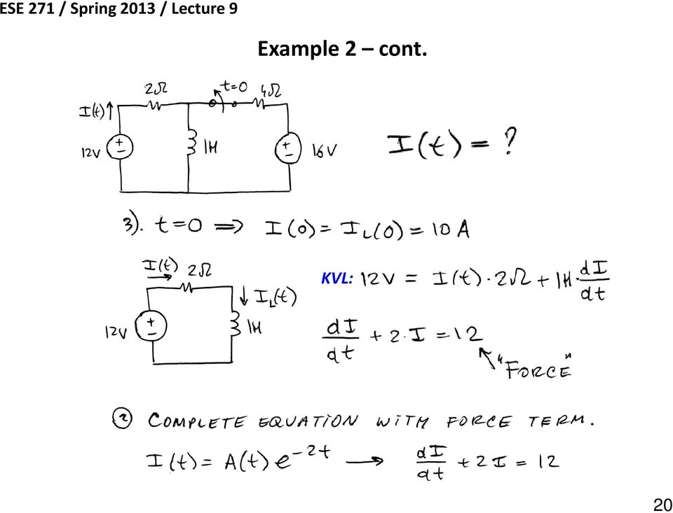
21 Example 2 cont. Find B from initial conditions: 21
22 Example 2 cont. 22
23 Superposition. 23
24 Superposition cont. 24
25 Superposition cont. 25
26 Superposition cont. 26
27 Superposition cont. 27
28 Example. DC steady state Energy stored in inductor will get dissipated in resistor. Eventually all voltages and currents will become zero since circuit will contain no sources and there is resistor that does not store but dissipates energy. To find the transient values of voltage and currents we will need to solve integrodifferential equation not an easy task, in general. 28
ES250: Electrical Science. HW7: Energy Storage Elements
 ES250: Electrical Science HW7: Energy Storage Elements Introduction This chapter introduces two more circuit elements, the capacitor and the inductor whose elements laws involve integration or differentiation;
Eðlisfræði 2, vor 2007
 [ Assignment View ] [ Print ] Eðlisfræði 2, vor 2007 30. Inductance Assignment is due at 2:00am on Wednesday, March 14, 2007 Credit for problems submitted late will decrease to 0% after the deadline has
Slide 1 / 26. Inductance. 2011 by Bryan Pflueger
 Slide 1 / 26 Inductance 2011 by Bryan Pflueger Slide 2 / 26 Mutual Inductance If two coils of wire are placed near each other and have a current passing through them, they will each induce an emf on one
Physics 2102 Lecture 19. Physics 2102
 Physics 2102 Jonathan Dowling Physics 2102 Lecture 19 Ch 30: Inductors and RL Circuits Nikolai Tesla What are we going to learn? A road map Electric charge Electric force on other electric charges Electric
April 1. Physics 272. Spring 2014 http://www.phys.hawaii.edu/~philipvd/pvd_14_spring_272_uhm.html. Prof. Philip von Doetinchem philipvd@hawaii.
 Physics 272 April 1 Spring 2014 http://www.phys.hawaii.edu/~philipvd/pvd_14_spring_272_uhm.html Prof. Philip von Doetinchem philipvd@hawaii.edu Phys272 - Spring 14 - von Doetinchem - 164 Summary Gauss's
EE301 Lesson 14 Reading: 10.1-10.4, 10.11-10.12, 11.1-11.4 and 11.11-11.13
 CAPACITORS AND INDUCTORS Learning Objectives EE301 Lesson 14 a. Define capacitance and state its symbol and unit of measurement. b. Predict the capacitance of a parallel plate capacitor. c. Analyze how
W03 Analysis of DC Circuits. Yrd. Doç. Dr. Aytaç Gören
 W03 Analysis of DC Circuits Yrd. Doç. Dr. Aytaç Gören ELK 2018 - Contents W01 Basic Concepts in Electronics W02 AC to DC Conversion W03 Analysis of DC Circuits (self and condenser) W04 Transistors and
Solution Derivations for Capa #11
 Solution Derivations for Capa #11 Caution: The symbol E is used interchangeably for energy and EMF. 1) DATA: V b = 5.0 V, = 155 Ω, L = 8.400 10 2 H. In the diagram above, what is the voltage across the
Edmund Li. Where is defined as the mutual inductance between and and has the SI units of Henries (H).
.") INDUCTANCE MUTUAL INDUCTANCE If we consider two neighbouring closed loops and with bounding surfaces respectively then a current through will create a magnetic field which will link with as the flux passes
INDUCTANCE MUTUAL INDUCTANCE If we consider two neighbouring closed loops and with bounding surfaces respectively then a current through will create a magnetic field which will link with as the flux passes
Homework #11 203-1-1721 Physics 2 for Students of Mechanical Engineering
 Homework #11 203-1-1721 Physics 2 for Students of Mechanical Engineering 2. A circular coil has a 10.3 cm radius and consists of 34 closely wound turns of wire. An externally produced magnetic field of
Induced voltages and Inductance Faraday s Law
 Induced voltages and Inductance Faraday s Law concept #1, 4, 5, 8, 13 Problem # 1, 3, 4, 5, 6, 9, 10, 13, 15, 24, 23, 25, 31, 32a, 34, 37, 41, 43, 51, 61 Last chapter we saw that a current produces a magnetic
12. The current in an inductor is changing at the rate of 100 A/s, and the inductor emf is 40 V. What is its self-inductance?
 12. The current in an inductor is changing at the rate of 100 A/s, and the inductor emf is 40 V. What is its self-inductance? From Equation 32-5, L = -E=(dI =dt) = 40 V=(100 A/s) = 0.4 H. 15. A cardboard
Capacitors in Circuits
 apacitors in ircuits apacitors store energy in the electric field E field created by the stored charge In circuit apacitor may be absorbing energy Thus causes circuit current to be reduced Effectively
Chapter 30 Inductance
 Chapter 30 Inductance - Mutual Inductance - Self-Inductance and Inductors - Magnetic-Field Energy - The R- Circuit - The -C Circuit - The -R-C Series Circuit . Mutual Inductance - A changing current in
RLC Resonant Circuits
 C esonant Circuits Andrew McHutchon April 20, 203 Capacitors and Inductors There is a lot of inconsistency when it comes to dealing with reactances of complex components. The format followed in this document
Linear DC Motors. 15.1 Magnetic Flux. 15.1.1 Permanent Bar Magnets
 Linear DC Motors The purpose of this supplement is to present the basic material needed to understand the operation of simple DC motors. This is intended to be used as the reference material for the linear
Objectives. Capacitors 262 CHAPTER 5 ENERGY
 Objectives Describe a capacitor. Explain how a capacitor stores energy. Define capacitance. Calculate the electrical energy stored in a capacitor. Describe an inductor. Explain how an inductor stores energy.
Circuits with inductors and alternating currents. Chapter 20 #45, 46, 47, 49
 Circuits with inductors and alternating currents Chapter 20 #45, 46, 47, 49 RL circuits Ch. 20 (last section) Symbol for inductor looks like a spring. An inductor is a circuit element that has a large
Electromagnetism Laws and Equations
 Electromagnetism Laws and Equations Andrew McHutchon Michaelmas 203 Contents Electrostatics. Electric E- and D-fields............................................. Electrostatic Force............................................2
Lecture 24. Inductance and Switching Power Supplies (how your solar charger voltage converter works)
") Lecture 24 Inductance and Switching Power Supplies (how your solar charger voltage converter works) Copyright 2014 by Mark Horowitz 1 Roadmap: How Does This Work? 2 Processor Board 3 More Detailed Roadmap
Lecture 24 Inductance and Switching Power Supplies (how your solar charger voltage converter works) Copyright 2014 by Mark Horowitz 1 Roadmap: How Does This Work? 2 Processor Board 3 More Detailed Roadmap
Inductance. Motors. Generators
 Inductance Motors Generators Self-inductance Self-inductance occurs when the changing flux through a circuit arises from the circuit itself. As the current increases, the magnetic flux through a loop due
Diodes have an arrow showing the direction of the flow.
 The Big Idea Modern circuitry depends on much more than just resistors and capacitors. The circuits in your computer, cell phone, Ipod depend on circuit elements called diodes, inductors, transistors,
Magnetic Circuits. Outline. Ampere s Law Revisited Review of Last Time: Magnetic Materials Magnetic Circuits Examples
 Magnetic Circuits Outline Ampere s Law Revisited Review of Last Time: Magnetic Materials Magnetic Circuits Examples 1 Electric Fields Magnetic Fields S ɛ o E da = ρdv B V = Q enclosed S da =0 GAUSS GAUSS
Coupled Inductors. Introducing Coupled Inductors
 Coupled Inductors From power distribution across large distances to radio transmissions, coupled inductors are used extensively in electrical applications. Their properties allow for increasing or decreasing
RUPHYS2272015 ( RUPHY227F2015 ) My Courses Course Settings University Physics with Modern Physics, 14e Young/Freedman
 My Courses Course Settings University Physics with Modern Physics, 14e Young/Freedman") Signed in as Jolie Cizewski, Instructor Help Sign Out RUPHYS2272015 ( RUPHY227F2015 ) My Courses Course Settings University Physics with Modern Physics, 14e Young/Freedman Course Home Assignments Roster
Signed in as Jolie Cizewski, Instructor Help Sign Out RUPHYS2272015 ( RUPHY227F2015 ) My Courses Course Settings University Physics with Modern Physics, 14e Young/Freedman Course Home Assignments Roster
Basic Laws Circuit Theorems Methods of Network Analysis Non-Linear Devices and Simulation Models
 EE Modul 1: Electric Circuits Theory Basic Laws Circuit Theorems Methods of Network Analysis Non-Linear Devices and Simulation Models EE Modul 1: Electric Circuits Theory Current, Voltage, Impedance Ohm
2. A conductor of length 2m moves at 4m/s at 30 to a uniform magnetic field of 0.1T. Which one of the following gives the e.m.f. generated?
 Extra Questions - 2 1. A straight length of wire moves through a uniform magnetic field. The e.m.f. produced across the ends of the wire will be maximum if it moves: a) along the lines of magnetic flux
Module 22: Inductance and Magnetic Field Energy
 Module 22: Inductance and Magnetic Field Energy 1 Module 22: Outline Self Inductance Energy in Inductors Circuits with Inductors: RL Circuit 2 Faraday s Law of Induction dφ = B dt Changing magnetic flux
Problem Solving 8: RC and LR Circuits
 MASSACHUSETTS INSTITUTE OF TECHNOLOGY Department of Physics Problem Solving 8: RC and LR Circuits Section Table and Group (e.g. L04 3C ) Names Hand in one copy per group at the end of the Friday Problem
Direction of Induced Current
 Direction of Induced Current Bar magnet moves through coil Current induced in coil A S N v Reverse pole Induced current changes sign B N S v v Coil moves past fixed bar magnet Current induced in coil as
= (0.400 A) (4.80 V) = 1.92 W = (0.400 A) (7.20 V) = 2.88 W
 (4.80 V) = 1.92 W = (0.400 A) (7.20 V) = 2.88 W") Physics 2220 Module 06 Homework 0. What are the magnitude and direction of the current in the 8 Ω resister in the figure? Assume the current is moving clockwise. Then use Kirchhoff's second rule: 3.00
Physics 2220 Module 06 Homework 0. What are the magnitude and direction of the current in the 8 Ω resister in the figure? Assume the current is moving clockwise. Then use Kirchhoff's second rule: 3.00
First Order Circuits. EENG223 Circuit Theory I
 First Order Circuits EENG223 Circuit Theory I First Order Circuits A first-order circuit can only contain one energy storage element (a capacitor or an inductor). The circuit will also contain resistance.
DEGREE: Bachelor's Degree in Industrial Electronics and Automation COURSE: 1º TERM: 2º WEEKLY PLANNING
 SESSION WEEK COURSE: Physics II DEGREE: Bachelor's Degree in Industrial Electronics and Automation COURSE: 1º TERM: 2º WEEKLY PLANNING DESCRIPTION GROUPS (mark ) Indicate YES/NO If the session needs 2
Lecture 22. Inductance. Magnetic Field Energy. Outline:
 Lecture 22. Inductance. Magnetic Field Energy. Outline: Self-induction and self-inductance. Inductance of a solenoid. The energy of a magnetic field. Alternative definition of inductance. Mutual Inductance.
Energy in Electrical Systems. Overview
 Energy in Electrical Systems Overview How can Potential Energy be stored in electrical systems? Battery Stored as chemical energy then transformed to electrical energy on usage Water behind a dam Water
Chapter 11. Inductors ISU EE. C.Y. Lee
 Chapter 11 Inductors Objectives Describe the basic structure and characteristics of an inductor Discuss various types of inductors Analyze series inductors Analyze parallel inductors Analyze inductive
Inductors. AC Theory. Module 3
 Module 3 AC Theory What you ll learn in Module 3. Section 3.1 Electromagnetic Induction. Magnetic Fields around Conductors. The Solenoid. Section 3.2 Inductance & Back e.m.f. The Unit of Inductance. Factors
Chapter 7 Direct-Current Circuits
 Chapter 7 Direct-Current Circuits 7. Introduction...7-7. Electromotive Force...7-3 7.3 Resistors in Series and in Parallel...7-5 7.4 Kirchhoff s Circuit Rules...7-7 7.5 Voltage-Current Measurements...7-9
Mutual Inductance and Transformers F3 3. r L = ω o
 utual Inductance and Transformers F3 1 utual Inductance & Transformers If a current, i 1, flows in a coil or circuit then it produces a magnetic field. Some of the magnetic flux may link a second coil
Current, Resistance and Electromotive Force. Young and Freedman Chapter 25
 Current, Resistance and Electromotive Force Young and Freedman Chapter 25 Electric Current: Analogy, water flowing in a pipe H 2 0 gallons/minute Flow Rate is the NET amount of water passing through a
EDEXCEL NATIONAL CERTIFICATE/DIPLOMA UNIT 67 - FURTHER ELECTRICAL PRINCIPLES NQF LEVEL 3 OUTCOME 1 TUTORIAL 1 - DIRECT CURRENT CIRCUIT THEOREMS
 EDEXCE NATIONA CERTIFICATE/DIPOMA UNIT 67 - FURTHER EECTRICA PRINCIPES NQF EVE 3 OUTCOME 1 TUTORIA 1 - DIRECT CURRENT CIRCUIT THEOREMS Unit content 1 Be able to apply direct current (DC) circuit analysis
Outline. Systems and Signals 214 / 244 & Energy Systems 244 / 344. Ideal Inductor. Ideal Inductor (cont... )
") Outline Systems and Signals 214 / 244 & Energy Systems 244 / 344 Inductance, Leakage Inductance, Mutual Inductance & Transformers 1 Inductor revision Ideal Inductor Non-Ideal Inductor Dr. P.J. Randewijk
Outline Systems and Signals 214 / 244 & Energy Systems 244 / 344 Inductance, Leakage Inductance, Mutual Inductance & Transformers 1 Inductor revision Ideal Inductor Non-Ideal Inductor Dr. P.J. Randewijk
Inductance and Magnetic Energy
 Chapter 11 Inductance and Magnetic Energy 11.1 Mutual Inductance... 11-3 Example 11.1 Mutual Inductance of Two Concentric Coplanar Loops... 11-5 11. Self-Inductance... 11-5 Example 11. Self-Inductance
Application Notes. Magnetics. Determining L min for Buck/Boost Converters
 Application Notes Magnetics etermining min for Buck/Boost onverters Fundamental oncepts 172 alculating Minimum nductance Buck Type onverters 174 Boost Type onverters 177 Buck-Boost onverters 180-171 APPATON
First Year (Electrical & Electronics Engineering)
") Z PRACTICAL WORK BOOK For The Course EE-113 Basic Electrical Engineering For First Year (Electrical & Electronics Engineering) Name of Student: Class: Batch : Discipline: Class Roll No.: Examination Seat
Z PRACTICAL WORK BOOK For The Course EE-113 Basic Electrical Engineering For First Year (Electrical & Electronics Engineering) Name of Student: Class: Batch : Discipline: Class Roll No.: Examination Seat
Principles and Working of DC and AC machines
 BITS Pilani Dubai Campus Principles and Working of DC and AC machines Dr Jagadish Nayak Constructional features BITS Pilani Dubai Campus DC Generator A generator consists of a stationary portion called
8 Speed control of Induction Machines
 8 Speed control of Induction Machines We have seen the speed torque characteristic of the machine. In the stable region of operation in the motoring mode, the curve is rather steep and goes from zero torque
2 A bank account for electricity II: flows and taxes
 PHYS 189 Lecture problems outline Feb 3, 2014 Resistors and Circuits Having introduced capacitors, we now expand our focus to another very important component of a circuit resistors. This entails more
PHY114 S11 Term Exam 3
 PHY4 S Term Exam S. G. Rajeev Mar 2 20 2:0 pm to :45 pm PLEASE write your workshop number and your workshop leader s name at the top of your book, so that you can collect your graded exams at the workshop.
1. The diagram below represents magnetic lines of force within a region of space.
 1. The diagram below represents magnetic lines of force within a region of space. 4. In which diagram below is the magnetic flux density at point P greatest? (1) (3) (2) (4) The magnetic field is strongest
Aircraft Electrical System
 Chapter 9 Aircraft Electrical System Introduction The satisfactory performance of any modern aircraft depends to a very great degree on the continuing reliability of electrical systems and subsystems.
CHAPTER 30: Inductance, Electromagnetic Oscillations, and AC Circuits
 HAPTE 3: Inductance, Electromagnetic Oscillations, and A ircuits esponses to Questions. (a) For the maximum value of the mutual inductance, place the coils close together, face to face, on the same axis.
VOLTAGE REGULATOR AND PARALLEL OPERATION
 VOLTAGE REGULATOR AND PARALLEL OPERATION Generator sets are operated in parallel to improve fuel economy and reliability of the power supply. Economy is improved with multiple paralleled generators by
Lecture Notes: ECS 203 Basic Electrical Engineering Semester 1/2010. Dr.Prapun Suksompong 1 June 16, 2010
 Sirindhorn International Institute of Technology Thammasat University School of Information, Computer and Communication Technology Lecture Notes: ECS 203 Basic Electrical Engineering Semester 1/2010 Dr.Prapun
DC GENERATOR THEORY. LIST the three conditions necessary to induce a voltage into a conductor.
 DC Generators DC generators are widely used to produce a DC voltage. The amount of voltage produced depends on a variety of factors. EO 1.5 LIST the three conditions necessary to induce a voltage into
MULTIPLE CHOICE. Choose the one alternative that best completes the statement or answers the question.
 MULTIPLE CHOICE. Choose the one alternative that best completes the statement or answers the question. 1) If the voltage at a point in space is zero, then the electric field must be A) zero. B) positive.
PHYS 222 Spring 2012 Final Exam. Closed books, notes, etc. No electronic device except a calculator.
 PHYS 222 Spring 2012 Final Exam Closed books, notes, etc. No electronic device except a calculator. NAME: (all questions with equal weight) 1. If the distance between two point charges is tripled, the
13 ELECTRIC MOTORS. 13.1 Basic Relations
 13 ELECTRIC MOTORS Modern underwater vehicles and surface vessels are making increased use of electrical actuators, for all range of tasks including weaponry, control surfaces, and main propulsion. This
Inductors & Inductance. Electronic Components
 Electronic Components Induction In 1824, Oersted discovered that current passing though a coil created a magnetic field capable of shifting a compass needle. Seven years later, Faraday and Henry discovered
Experiment NO.3 Series and parallel connection
 Experiment NO.3 Series and parallel connection Object To study the properties of series and parallel connection. Apparatus 1. DC circuit training system 2. Set of wires. 3. DC Power supply 4. Digital A.V.O.
Objectives. Electric Current
 Objectives Define electrical current as a rate. Describe what is measured by ammeters and voltmeters. Explain how to connect an ammeter and a voltmeter in an electrical circuit. Explain why electrons travel
Introduction to Electricity & Magnetism. Dr Lisa Jardine-Wright Cavendish Laboratory
 Introduction to Electricity & Magnetism Dr Lisa Jardine-Wright Cavendish Laboratory Examples of uses of electricity Christmas lights Cars Electronic devices Human body Electricity? Electricity is the presence
Let s examine the response of the circuit shown on Figure 1. The form of the source voltage Vs is shown on Figure 2. R. Figure 1.
 Examples of Transient and RL Circuits. The Series RLC Circuit Impulse response of Circuit. Let s examine the response of the circuit shown on Figure 1. The form of the source voltage Vs is shown on Figure.
= V peak 2 = 0.707V peak
 BASIC ELECTRONICS - RECTIFICATION AND FILTERING PURPOSE Suppose that you wanted to build a simple DC electronic power supply, which operated off of an AC input (e.g., something you might plug into a standard
EXAMPLE 8: An Electrical System (Mechanical-Electrical Analogy)
") EXAMPLE 8: An Electrical System (Mechanical-Electrical Analogy) A completely analogous procedure can be used to find the state equations of electrical systems (and, ultimately, electro-mechanical systems
EXAMPLE 8: An Electrical System (Mechanical-Electrical Analogy) A completely analogous procedure can be used to find the state equations of electrical systems (and, ultimately, electro-mechanical systems
Application Note. So You Need to Measure Some Inductors?
 So You Need to Measure Some nductors? Take a look at the 1910 nductance Analyzer. Although specifically designed for production testing of inductors and coils, in addition to measuring inductance (L),
Magnetism Basics. Magnetic Domains: atomic regions of aligned magnetic poles Random Alignment Ferromagnetic Alignment. Net Effect = Zero!
 Magnetism Basics Source: electric currents Magnetic Domains: atomic regions of aligned magnetic poles Random Alignment Ferromagnetic Alignment Net Effect = Zero! Net Effect = Additive! Bipolar: all magnets
Fundamentals of Electrical Engineering 2 Grundlagen der Elektrotechnik 2
 Fundamentals of Electrical Engineering 2 Grundlagen der Elektrotechnik 2 Chapter: Sinusoidal Steady State Analysis / Netzwerkanalyse bei harmonischer Erregung Michael E. Auer Source of figures: Alexander/Sadiku:
Equivalent Circuits and Transfer Functions
 R eq isc Equialent Circuits and Transfer Functions Samantha R Summerson 14 September, 009 1 Equialent Circuits eq ± Figure 1: Théenin equialent circuit. i sc R eq oc Figure : Mayer-Norton equialent circuit.
45. The peak value of an alternating current in a 1500-W device is 5.4 A. What is the rms voltage across?
 PHYS Practice Problems hapters 8- hapter 8. 45. The peak value of an alternating current in a 5-W device is 5.4 A. What is the rms voltage across? The power and current can be used to find the peak voltage,
6 J - vector electric current density (A/m2 )
") Determination of Antenna Radiation Fields Using Potential Functions Sources of Antenna Radiation Fields 6 J - vector electric current density (A/m2 ) M - vector magnetic current density (V/m 2 ) Some problems
Determination of Antenna Radiation Fields Using Potential Functions Sources of Antenna Radiation Fields 6 J - vector electric current density (A/m2 ) M - vector magnetic current density (V/m 2 ) Some problems
How To Understand And Understand The Theory Of Electricity
 DIRECT CURRENT AND ALTERNATING CURRENT SYSTEMS N. Rajkumar, Research Fellow, Energy Systems Group, City University Northampton Square, London EC1V 0HB, UK Keywords: Electrical energy, direct current, alternating
THE LUCAS C40 DYNAMO & ITS ARMATURE.
 THE LUCAS C40 DYNAMO & ITS ARMATURE. H. Holden, March 2011. The Dynamo as a DC generating machine was used extensively in the pre- Alternator era, from the early 1900 s up to the late 1960 s and early
Impedance Matching and Matching Networks. Valentin Todorow, December, 2009
 Impedance Matching and Matching Networks Valentin Todorow, December, 2009 RF for Plasma Processing - Definition of RF What is RF? The IEEE Standard Dictionary of Electrical and Electronics Terms defines
104 Practice Exam 2-3/21/02
 104 Practice Exam 2-3/21/02 1. Two electrons are located in a region of space where the magnetic field is zero. Electron A is at rest; and electron B is moving westward with a constant velocity. A non-zero
Magnetic Field of a Circular Coil Lab 12
 HB 11-26-07 Magnetic Field of a Circular Coil Lab 12 1 Magnetic Field of a Circular Coil Lab 12 Equipment- coil apparatus, BK Precision 2120B oscilloscope, Fluke multimeter, Wavetek FG3C function generator,
WINDING RESISTANCE TESTING
 WINDING RESISTANCE TESTING WINDING RESISTANCE TEST SET, MODEL WRT-100 ADWEL INTERNATIONAL LTD. 60 Ironside Crescent, Unit 9 Scarborough, Ontario, Canada M1X 1G4 Telephone: (416) 321-1988 Fax: (416) 321-1991
Series and Parallel Circuits
 Direct Current (DC) Direct current (DC) is the unidirectional flow of electric charge. The term DC is used to refer to power systems that use refer to the constant (not changing with time), mean (average)
EEE1001/PHY1002. Magnetic Circuits. The circuit is of length l=2πr. B andφ circulate
 1 Magnetic Circuits Just as we view electric circuits as related to the flow of charge, we can also view magnetic flux flowing around a magnetic circuit. The sum of fluxes entering a point must sum to
Alternating Current Circuits and Electromagnetic Waves
 Arecibo, a large radio telescope in Puerto Rico, gathers electromagnetic radiation in the form of radio waves. These long wavelengths pass through obscuring dust clouds, allowing astronomers to create
Small Signal Analysis of a PMOS transistor Consider the following PMOS transistor to be in saturation. Then, 1 2
 Small Signal Analysis of a PMOS transistor Consider the following PMOS transistor to be in saturation. Then, 1 I SD = µ pcox( VSG Vtp)^2(1 + VSDλ) 2 From this equation it is evident that I SD is a function
Your Comments. This was a very confusing prelecture. Do you think you could go over thoroughly how the LC circuits work qualitatively?
 Your omments I am not feeling great about this mierm...some of this stuff is really confusing still and I don't know if I can shove everything into my brain in time, especially after spring break. an you
AP Physics Electricity and Magnetism #4 Electrical Circuits, Kirchoff s Rules
 Name Period AP Physics Electricity and Magnetism #4 Electrical Circuits, Kirchoff s Rules Dr. Campbell 1. Four 240 Ω light bulbs are connected in series. What is the total resistance of the circuit? What
DEGREE: Bachelor in Biomedical Engineering YEAR: 2 TERM: 2 WEEKLY PLANNING
 SESSION WEEK COURSE: Electronic Technology in Biomedicine DEGREE: Bachelor in Biomedical Engineering YEAR: 2 TERM: 2 WEEKLY PLANNING DESCRIPTION GROUPS (mark X) SPECIAL ROOM FOR SESSION (Computer class
CURRENT ELECTRICITY INTRODUCTION TO RESISTANCE, CAPACITANCE AND INDUCTANCE
 CURRENT ELECTRICITY INTRODUCTION TO RESI STANCE, CAPACITANCE AND INDUCTANCE P R E A M B L E This problem is adapted from an on-line knowledge enhancement module for a PGCE programme. It is used to cover
Chapter 7. DC Circuits
 Chapter 7 DC Circuits 7.1 Introduction... 7-3 Example 7.1.1: Junctions, branches and loops... 7-4 7.2 Electromotive Force... 7-5 7.3 Electrical Energy and Power... 7-9 7.4 Resistors in Series and in Parallel...
Series and Parallel Circuits
 Series and Parallel Circuits Direct-Current Series Circuits A series circuit is a circuit in which the components are connected in a line, one after the other, like railroad cars on a single track. There
EE 221 Circuits II. Chapter 13 Magnetically Coupled Circuits
 EE Circuits II Chapter 3 Magnetically Coupled Circuits Magnetically Coupled Circuits 3. What is a transformer? 3. Mutual Inductance 3.3 Energy in a Coupled Circuit 3.4 inear Transformers 3.5 Ideal Transformers
9: Capacitors and Inductors
 E1.1 Analysis of Circuits (2015-7150) and : 9 1 / 12 A capacitor is formed from two conducting plates separated by a thin insulating layer. If a currentiflows, positive change,q, will accumulate on the
CHAPTER 28 ELECTRIC CIRCUITS
 CHAPTER 8 ELECTRIC CIRCUITS 1. Sketch a circuit diagram for a circuit that includes a resistor R 1 connected to the positive terminal of a battery, a pair of parallel resistors R and R connected to the
Direct Current Motors
 Direct Current Motors DC MOTORS The DC machine can operate as a generator and as a motor. Chap 5. Electrical Machines by Wildi, 6 e Lecturer: R. Alba-Flores Alfred State College Spring 2008 When a DC machine
Magnetic electro-mechanical machines
 Magnetic electro-mechanical machines Lorentz Force A magnetic field exerts force on a moving charge. The Lorentz equation: f = q(e + v B) f: force exerted on charge q E: electric field strength v: velocity
CHAPTER - 1. Chapter ONE: WAVES CHAPTER - 2. Chapter TWO: RAY OPTICS AND OPTICAL INSTRUMENTS. CHAPTER - 3 Chapter THREE: WAVE OPTICS PERIODS PERIODS
 BOARD OF INTERMEDIATE EDUCATION, A.P., HYDERABAD REVISION OF SYLLABUS Subject PHYSICS-II (w.e.f 2013-14) Chapter ONE: WAVES CHAPTER - 1 1.1 INTRODUCTION 1.2 Transverse and longitudinal waves 1.3 Displacement
DOE FUNDAMENTALS HANDBOOK ELECTRICAL SCIENCE Volume 3 of 4
 DOE-HDBK-1011/3-92 JUNE 1992 DOE FUNDAMENTALS HANDBOOK ELECTRICAL SCIENCE Volume 3 of 4 U.S. Department of Energy Washington, D.C. 20585 FSC-6910 Distribution Statement A. Approved for public release;
Force on Moving Charges in a Magnetic Field
 [ Assignment View ] [ Eðlisfræði 2, vor 2007 27. Magnetic Field and Magnetic Forces Assignment is due at 2:00am on Wednesday, February 28, 2007 Credit for problems submitted late will decrease to 0% after
EDEXCEL NATIONAL CERTIFICATE/DIPLOMA UNIT 5 - ELECTRICAL AND ELECTRONIC PRINCIPLES NQF LEVEL 3 OUTCOME 4 - ALTERNATING CURRENT
 EDEXCEL NATIONAL CERTIFICATE/DIPLOMA UNIT 5 - ELECTRICAL AND ELECTRONIC PRINCIPLES NQF LEVEL 3 OUTCOME 4 - ALTERNATING CURRENT 4 Understand single-phase alternating current (ac) theory Single phase AC
BASIC ELECTRONICS AC CIRCUIT ANALYSIS. December 2011
 AM 5-202 BASIC ELECTRONICS AC CIRCUIT ANALYSIS December 2011 DISTRIBUTION RESTRICTION: Approved for Pubic Release. Distribution is unlimited. DEPARTMENT OF THE ARMY MILITARY AUXILIARY RADIO SYSTEM FORT
SCHWEITZER ENGINEERING LABORATORIES, COMERCIAL LTDA.
 Pocket book of Electrical Engineering Formulas Content 1. Elementary Algebra and Geometry 1. Fundamental Properties (real numbers) 1 2. Exponents 2 3. Fractional Exponents 2 4. Irrational Exponents 2 5.
Inductors in AC Circuits
 Inductors in AC Circuits Name Section Resistors, inductors, and capacitors all have the effect of modifying the size of the current in an AC circuit and the time at which the current reaches its maximum
Inductors and Capacitors Energy Storage Devices
 Inuctors an Capacitors Energy Storage Devices Aims: To know: Basics of energy storage evices. Storage leas to time elays. Basic equations for inuctors an capacitors. To be able to o escribe: Energy storage