Homework # Physics 2 for Students of Mechanical Engineering
|
|
|
- Harry Henderson
- 10 years ago
- Views:
Transcription
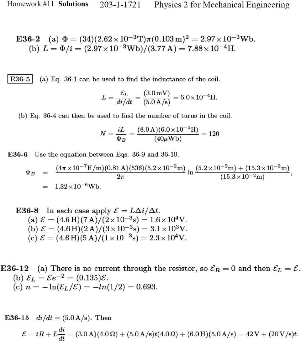
1 Homework # Physics 2 for Students of Mechanical Engineering 2. A circular coil has a 10.3 cm radius and consists of 34 closely wound turns of wire. An externally produced magnetic field of 2.62 mt is perpendicular to the coil. (a) If no current is in the coil, what is the number of flux linkages, N B, for the solenoid. (b) When the current in the coil is 3.77 A in a certain direction, the net flux through the coil is found to vanish. Find the inductance of the coil. 5. The inductance of a closely wound N-turn coil is such that an emf of 3.0 mv is induced when the current changes at the rate of 5.0 A/s. A steady state current of 8.0 A produces a magnetic flux of 40 Wb through each turn. (a) Calculate the inductance of the coil. (b) How many turns does the coil have? 6. A toroid having a 5.20 cm square cross-section and an inside radius of 15.3 cm has 536 turns of wire and carries a current of 810 ma. Calculate the magnetic flux through a cross-section. 8. The current i through a 4.6 H inductor varies with time t as shown on the graph of Fig below. Calculate the induced emf during the time intervals (a) t = 0 to t =2 ms, (b) t = 2 ms to t = 5 ms, and (c) t = 5 ms to t = 6 ms. (Ignore the behavior at the ends of each interval.) 12. Consider the LR circuit of Fig below. (a) In terms of the battery emf, what is the induced emf L when the switch has just been closed on a? (b) What is L after two time constants? (c) After how many time constants will L bee just one-half of the battery emf?

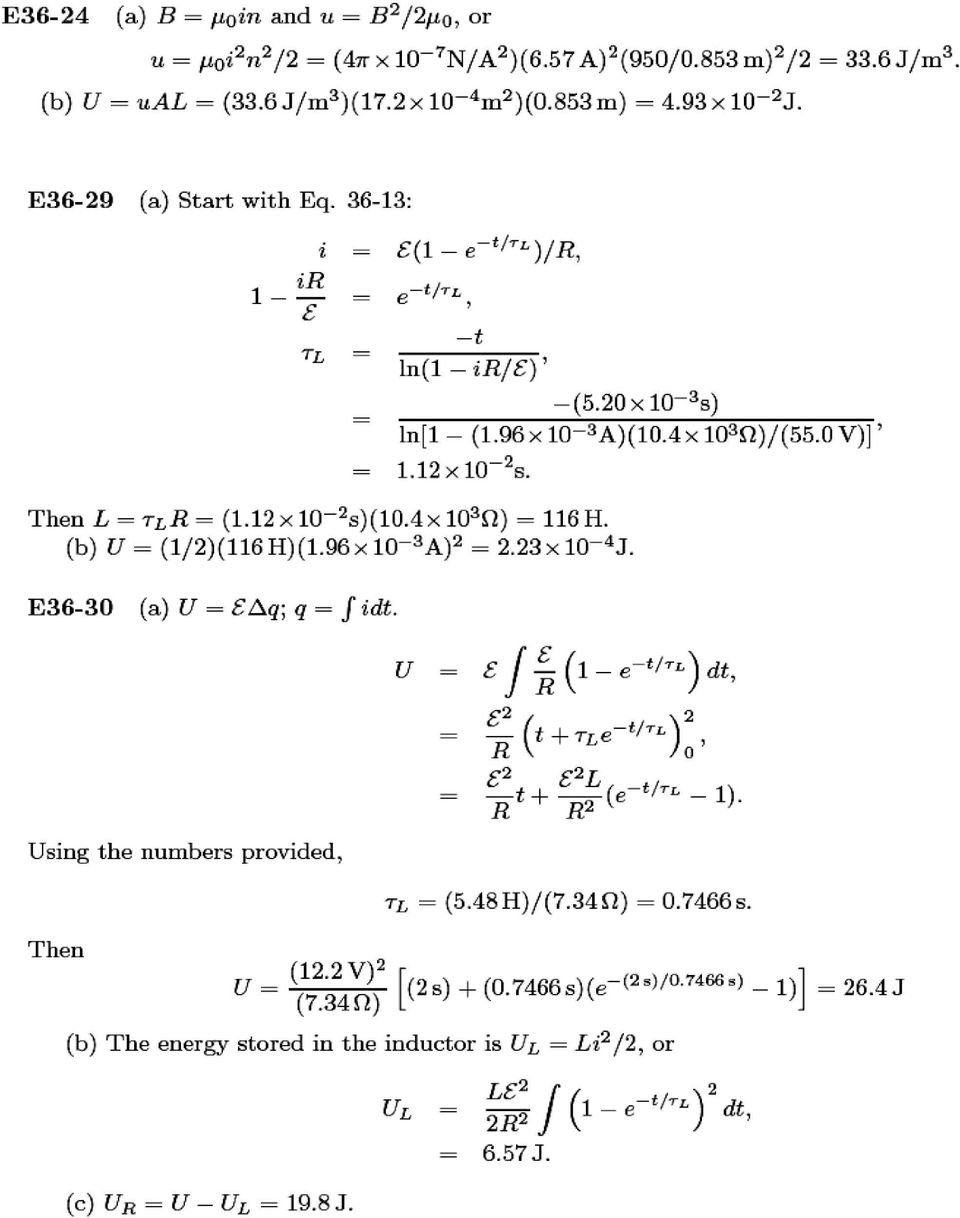
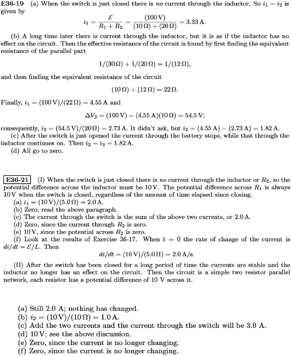
2 15. Suppose the emf of the battery in the circuit of Fig above (with the switch closed on a) varies with time to so that current is given by i(t) = (3.0 A) + (5.0 A/s)t. Take R = 4.0, L = 6.0 H, and find an expression for the battery emf as a function of time. (Hint: Apply the loop rule.) 19. In Fig below, = 100 V, R 1 = 10, R 2 = 20, R 3 = 30, and L = 2.0 H. Find the values of i 1 and i 2 (a) immediately after switch S is closed, (b) a long time later, (c) immediately after switch S is opened again, and (d) a long time later. 21. In the circuit shown in Fig below, = 10 V, R 1 = 5, R 2 = 10, and L = 5.0 H. For the two separate conditions (I) switch S just closed and (II) switch S closed for a long time, calculate (a) the current i 1 through R 1, (b) the current i 2 through R 2, (c) the current i through the switch, (d) the potential difference across R 2, (e) the potential difference across L, and (f) di 2 /dt. 24. A solenoid 85.3 cm long has a cross-sectional area of 17.2 cm 2. There are 950 turns of wire carrying a current of 6.57 A. (a) Calculate the magnetic field energy density inside the solenoid. (b) Find the total energy stored in the magnetic field inside the solenoid. (Neglect effects near the ends of the solenoid.) 29. A coil is connected in series with a 10.4 k resistor. When a 55.0 V battery is applied to the two elements, the current reaches a value of 1.96 ma after 5.20 ms. (a) Find the inductance of the coil. (b) How much energy is stored in the coil at this same moment? 30. For the circuit of Fig above, assume that = 12.2 V, R = 7.34, and L = 5.48 H. The battery is connected at time t = 0. (a) How much energy is delivered by the battery during the first 2.0 s? (b) How much of this energy is stored in the magnetic field of the inductor? (c) How much energy has been dissipated as heat in the resistor?
 switch S just closed and (II) switch S closed for a long time, calculate (a) the current i 1 through R 1, (b) the current i 2 through R 2, (c) the current i")
3 42. An oscillating LC circuit consisting of a 1.13 nf capacitor and a 3.17 mh coil has a peak potential drop of 2.87 V. Find (a) the maximum charge on the capacitor, (b) the peak current in the circuit, and (c) the maximum energy stored in the magnetic field of the coil. 44. In the circuit shown in Fig below, the switch has been in position a for a very long time before it is thrown to position b. (a) Calculate the frequency of the resulting oscillating current. (b) What will be the amplitude of the current oscillations? 45. An LC circuit has an inductance of 3.0 mh and a capacitance of 10 F. Calculate (a) the angular frequency and (b) the period of oscillation. (c) At time t = 0 the capacitor is charged to 200 C, and the current is zero. Sketch roughly the charge on the capacitor as a function of time. 52. A single loop circuit consists of a 7.22 resistor, a 12.3 H inductor, and a 3.18 F capacitor. Initially, the capacitor has a charge of 6.31 C and the current is zero. Calculate the charge on the capacitor N complete cycles later for N = 5, 10, and How much resistance R should be connected to an inductor L = 220 mh and capacitor C = 12 F in series in order that the maximum charge on the capacitor decays to 99% of its initial value in 50 cycles?
 What will be the amplitude of the current oscillations? 45. An LC circuit has an inductance of 3.0 mh and a capacitance of 10 F.")
4
5

6
7
Solution Derivations for Capa #11
 Solution Derivations for Capa #11 Caution: The symbol E is used interchangeably for energy and EMF. 1) DATA: V b = 5.0 V, = 155 Ω, L = 8.400 10 2 H. In the diagram above, what is the voltage across the
Slide 1 / 26. Inductance. 2011 by Bryan Pflueger
 Slide 1 / 26 Inductance 2011 by Bryan Pflueger Slide 2 / 26 Mutual Inductance If two coils of wire are placed near each other and have a current passing through them, they will each induce an emf on one
Eðlisfræði 2, vor 2007
 [ Assignment View ] [ Print ] Eðlisfræði 2, vor 2007 30. Inductance Assignment is due at 2:00am on Wednesday, March 14, 2007 Credit for problems submitted late will decrease to 0% after the deadline has
12. The current in an inductor is changing at the rate of 100 A/s, and the inductor emf is 40 V. What is its self-inductance?
 12. The current in an inductor is changing at the rate of 100 A/s, and the inductor emf is 40 V. What is its self-inductance? From Equation 32-5, L = -E=(dI =dt) = 40 V=(100 A/s) = 0.4 H. 15. A cardboard
Physics 2102 Lecture 19. Physics 2102
 Physics 2102 Jonathan Dowling Physics 2102 Lecture 19 Ch 30: Inductors and RL Circuits Nikolai Tesla What are we going to learn? A road map Electric charge Electric force on other electric charges Electric
Induced voltages and Inductance Faraday s Law
 Induced voltages and Inductance Faraday s Law concept #1, 4, 5, 8, 13 Problem # 1, 3, 4, 5, 6, 9, 10, 13, 15, 24, 23, 25, 31, 32a, 34, 37, 41, 43, 51, 61 Last chapter we saw that a current produces a magnetic
Circuits with inductors and alternating currents. Chapter 20 #45, 46, 47, 49
 Circuits with inductors and alternating currents Chapter 20 #45, 46, 47, 49 RL circuits Ch. 20 (last section) Symbol for inductor looks like a spring. An inductor is a circuit element that has a large
45. The peak value of an alternating current in a 1500-W device is 5.4 A. What is the rms voltage across?
 PHYS Practice Problems hapters 8- hapter 8. 45. The peak value of an alternating current in a 5-W device is 5.4 A. What is the rms voltage across? The power and current can be used to find the peak voltage,
ES250: Electrical Science. HW7: Energy Storage Elements
 ES250: Electrical Science HW7: Energy Storage Elements Introduction This chapter introduces two more circuit elements, the capacitor and the inductor whose elements laws involve integration or differentiation;
104 Practice Exam 2-3/21/02
 104 Practice Exam 2-3/21/02 1. Two electrons are located in a region of space where the magnetic field is zero. Electron A is at rest; and electron B is moving westward with a constant velocity. A non-zero
PHY114 S11 Term Exam 3
 PHY4 S Term Exam S. G. Rajeev Mar 2 20 2:0 pm to :45 pm PLEASE write your workshop number and your workshop leader s name at the top of your book, so that you can collect your graded exams at the workshop.
EE301 Lesson 14 Reading: 10.1-10.4, 10.11-10.12, 11.1-11.4 and 11.11-11.13
 CAPACITORS AND INDUCTORS Learning Objectives EE301 Lesson 14 a. Define capacitance and state its symbol and unit of measurement. b. Predict the capacitance of a parallel plate capacitor. c. Analyze how
Diodes have an arrow showing the direction of the flow.
 The Big Idea Modern circuitry depends on much more than just resistors and capacitors. The circuits in your computer, cell phone, Ipod depend on circuit elements called diodes, inductors, transistors,
MULTIPLE CHOICE. Choose the one alternative that best completes the statement or answers the question.
 MULTIPLE CHOICE. Choose the one alternative that best completes the statement or answers the question. 1) If the voltage at a point in space is zero, then the electric field must be A) zero. B) positive.
Last time : energy storage elements capacitor.
 Last time : energy storage elements capacitor. Charge on plates Energy stored in the form of electric field Passive sign convention Vlt Voltage drop across real capacitor can not change abruptly because
Chapter 11. Inductors ISU EE. C.Y. Lee
 Chapter 11 Inductors Objectives Describe the basic structure and characteristics of an inductor Discuss various types of inductors Analyze series inductors Analyze parallel inductors Analyze inductive
Problem 1 (25 points)
") MASSACHUSETTS INSTITUTE OF TECHNOLOGY Department of Physics 8.02 Spring 2012 Exam Three Solutions Problem 1 (25 points) Question 1 (5 points) Consider two circular rings of radius R, each perpendicular
MASSACHUSETTS INSTITUTE OF TECHNOLOGY Department of Physics 8.02 Spring 2012 Exam Three Solutions Problem 1 (25 points) Question 1 (5 points) Consider two circular rings of radius R, each perpendicular
PHYS 222 Spring 2012 Final Exam. Closed books, notes, etc. No electronic device except a calculator.
 PHYS 222 Spring 2012 Final Exam Closed books, notes, etc. No electronic device except a calculator. NAME: (all questions with equal weight) 1. If the distance between two point charges is tripled, the
Problem Solving 8: RC and LR Circuits
 MASSACHUSETTS INSTITUTE OF TECHNOLOGY Department of Physics Problem Solving 8: RC and LR Circuits Section Table and Group (e.g. L04 3C ) Names Hand in one copy per group at the end of the Friday Problem
CHAPTER 30: Inductance, Electromagnetic Oscillations, and AC Circuits
 HAPTE 3: Inductance, Electromagnetic Oscillations, and A ircuits esponses to Questions. (a) For the maximum value of the mutual inductance, place the coils close together, face to face, on the same axis.
Lecture 24. Inductance and Switching Power Supplies (how your solar charger voltage converter works)
") Lecture 24 Inductance and Switching Power Supplies (how your solar charger voltage converter works) Copyright 2014 by Mark Horowitz 1 Roadmap: How Does This Work? 2 Processor Board 3 More Detailed Roadmap
Lecture 24 Inductance and Switching Power Supplies (how your solar charger voltage converter works) Copyright 2014 by Mark Horowitz 1 Roadmap: How Does This Work? 2 Processor Board 3 More Detailed Roadmap
Direction of Induced Current
 Direction of Induced Current Bar magnet moves through coil Current induced in coil A S N v Reverse pole Induced current changes sign B N S v v Coil moves past fixed bar magnet Current induced in coil as
Chapter 12 Driven RLC Circuits
 hapter Driven ircuits. A Sources... -. A ircuits with a Source and One ircuit Element... -3.. Purely esistive oad... -3.. Purely Inductive oad... -6..3 Purely apacitive oad... -8.3 The Series ircuit...
Edmund Li. Where is defined as the mutual inductance between and and has the SI units of Henries (H).
.") INDUCTANCE MUTUAL INDUCTANCE If we consider two neighbouring closed loops and with bounding surfaces respectively then a current through will create a magnetic field which will link with as the flux passes
INDUCTANCE MUTUAL INDUCTANCE If we consider two neighbouring closed loops and with bounding surfaces respectively then a current through will create a magnetic field which will link with as the flux passes
RUPHYS2272015 ( RUPHY227F2015 ) My Courses Course Settings University Physics with Modern Physics, 14e Young/Freedman
 My Courses Course Settings University Physics with Modern Physics, 14e Young/Freedman") Signed in as Jolie Cizewski, Instructor Help Sign Out RUPHYS2272015 ( RUPHY227F2015 ) My Courses Course Settings University Physics with Modern Physics, 14e Young/Freedman Course Home Assignments Roster
Signed in as Jolie Cizewski, Instructor Help Sign Out RUPHYS2272015 ( RUPHY227F2015 ) My Courses Course Settings University Physics with Modern Physics, 14e Young/Freedman Course Home Assignments Roster
Inductance. Motors. Generators
 Inductance Motors Generators Self-inductance Self-inductance occurs when the changing flux through a circuit arises from the circuit itself. As the current increases, the magnetic flux through a loop due
April 1. Physics 272. Spring 2014 http://www.phys.hawaii.edu/~philipvd/pvd_14_spring_272_uhm.html. Prof. Philip von Doetinchem philipvd@hawaii.
 Physics 272 April 1 Spring 2014 http://www.phys.hawaii.edu/~philipvd/pvd_14_spring_272_uhm.html Prof. Philip von Doetinchem [email protected] Phys272 - Spring 14 - von Doetinchem - 164 Summary Gauss's
Alternating-Current Circuits
 hapter 1 Alternating-urrent ircuits 1.1 A Sources... 1-1. Simple A circuits... 1-3 1..1 Purely esistive load... 1-3 1.. Purely Inductive oad... 1-5 1..3 Purely apacitive oad... 1-7 1.3 The Series ircuit...
Magnetic Circuits. Outline. Ampere s Law Revisited Review of Last Time: Magnetic Materials Magnetic Circuits Examples
 Magnetic Circuits Outline Ampere s Law Revisited Review of Last Time: Magnetic Materials Magnetic Circuits Examples 1 Electric Fields Magnetic Fields S ɛ o E da = ρdv B V = Q enclosed S da =0 GAUSS GAUSS
Chapter 30 Inductance
 Chapter 30 Inductance - Mutual Inductance - Self-Inductance and Inductors - Magnetic-Field Energy - The R- Circuit - The -C Circuit - The -R-C Series Circuit . Mutual Inductance - A changing current in
Inductance and Magnetic Energy
 Chapter 11 Inductance and Magnetic Energy 11.1 Mutual Inductance... 11-3 Example 11.1 Mutual Inductance of Two Concentric Coplanar Loops... 11-5 11. Self-Inductance... 11-5 Example 11. Self-Inductance
Lecture 22. Inductance. Magnetic Field Energy. Outline:
 Lecture 22. Inductance. Magnetic Field Energy. Outline: Self-induction and self-inductance. Inductance of a solenoid. The energy of a magnetic field. Alternative definition of inductance. Mutual Inductance.
Faraday s Law of Induction
 Chapter 10 Faraday s Law of Induction 10.1 Faraday s Law of Induction...10-10.1.1 Magnetic Flux...10-3 10.1. Lenz s Law...10-5 10. Motional EMF...10-7 10.3 Induced Electric Field...10-10 10.4 Generators...10-1
Phys222 Winter 2012 Quiz 4 Chapters 29-31. Name
 Name If you think that no correct answer is provided, give your answer, state your reasoning briefly; append additional sheet of paper if necessary. 1. A particle (q = 5.0 nc, m = 3.0 µg) moves in a region
2. A conductor of length 2m moves at 4m/s at 30 to a uniform magnetic field of 0.1T. Which one of the following gives the e.m.f. generated?
 Extra Questions - 2 1. A straight length of wire moves through a uniform magnetic field. The e.m.f. produced across the ends of the wire will be maximum if it moves: a) along the lines of magnetic flux
Physics 6C, Summer 2006 Homework 2 Solutions
 Physics 6C, Summer 006 Homework Solutions All problems are from the nd edition of Walker. Numerical values are different for each student. Chapter 3 Problems. Figure 3-30 below shows a circuit containing
Application Note. So You Need to Measure Some Inductors?
 So You Need to Measure Some nductors? Take a look at the 1910 nductance Analyzer. Although specifically designed for production testing of inductors and coils, in addition to measuring inductance (L),
Capacitors in Circuits
 apacitors in ircuits apacitors store energy in the electric field E field created by the stored charge In circuit apacitor may be absorbing energy Thus causes circuit current to be reduced Effectively
Chapter 35 Alternating Current Circuits
 hapter 35 Alternating urrent ircuits ac-ircuits Phasor Diagrams Resistors, apacitors and nductors in ac-ircuits R ac-ircuits ac-ircuit power. Resonance Transformers ac ircuits Alternating currents and
Iron Powder Cores for Switchmode Power Supply Inductors. by: Jim Cox
 HOME APPLICATION NOTES Iron Powder Cores for Switchmode Power Supply Inductors by: Jim Cox Purpose: The purpose of this application note is to cover the properties of iron powder as a magnetic core material
An equivalent circuit of a loop antenna.
 3.2.1. Circuit Modeling: Loop Impedance A loop antenna can be represented by a lumped circuit when its dimension is small with respect to a wavelength. In this representation, the circuit parameters (generally
Module 22: Inductance and Magnetic Field Energy
 Module 22: Inductance and Magnetic Field Energy 1 Module 22: Outline Self Inductance Energy in Inductors Circuits with Inductors: RL Circuit 2 Faraday s Law of Induction dφ = B dt Changing magnetic flux
Alternating Current Circuits and Electromagnetic Waves
 Arecibo, a large radio telescope in Puerto Rico, gathers electromagnetic radiation in the form of radio waves. These long wavelengths pass through obscuring dust clouds, allowing astronomers to create
Candidate Number. General Certificate of Education Advanced Level Examination June 2014
 entre Number andidate Number Surname Other Names andidate Signature General ertificate of Education dvanced Level Examination June 214 Physics PHY4/1 Unit 4 Fields and Further Mechanics Section Wednesday
 Last Name: First Name: Physics 102 Spring 2006: Exam #2 Multiple-Choice Questions 1. A charged particle, q, is moving with speed v perpendicular to a uniform magnetic field. A second identical charged
Physics 121 Sample Common Exam 3 NOTE: ANSWERS ARE ON PAGE 6. Instructions: 1. In the formula F = qvxb:
 Physics 121 Sample Common Exam 3 NOTE: ANSWERS ARE ON PAGE 6 Signature Name (Print): 4 Digit ID: Section: Instructions: Answer all questions 24 multiple choice questions. You may need to do some calculation.
Inductors. AC Theory. Module 3
 Module 3 AC Theory What you ll learn in Module 3. Section 3.1 Electromagnetic Induction. Magnetic Fields around Conductors. The Solenoid. Section 3.2 Inductance & Back e.m.f. The Unit of Inductance. Factors
Chapter 30 Inductance, Electromagnetic Oscillations, and AC Circuits. Copyright 2009 Pearson Education, Inc.
 Chapter 30 Inductance, Electromagnetic Oscillations, and AC Circuits 30-1 Mutual Inductance Mutual inductance: a changing current in one coil will induce a current in a second coil: Coil 1 produces a flux
Coupling Magnetic Signals to a SQUID Amplifier
 SQUID Application Note 105-0 Coupling Magnetic Signals to a SQUID Amplifier Matching the effective inductances of the Pickup Coil and the Input Coil to detect and couple magnetic flux maximizes the sensitivity
Candidate Number. General Certificate of Education Advanced Level Examination June 2010
 entre Number andidate Number Surname Other Names andidate Signature General ertificate of Education dvanced Level Examination June 1 Physics PHY4/1 Unit 4 Fields and Further Mechanics Section Friday 18
Objectives. Capacitors 262 CHAPTER 5 ENERGY
 Objectives Describe a capacitor. Explain how a capacitor stores energy. Define capacitance. Calculate the electrical energy stored in a capacitor. Describe an inductor. Explain how an inductor stores energy.
First Order Circuits. EENG223 Circuit Theory I
 First Order Circuits EENG223 Circuit Theory I First Order Circuits A first-order circuit can only contain one energy storage element (a capacitor or an inductor). The circuit will also contain resistance.
Candidate Number. General Certificate of Education Advanced Level Examination June 2012
 entre Number andidate Number Surname Other Names andidate Signature General ertificate of Education dvanced Level Examination June 212 Physics PHY4/1 Unit 4 Fields and Further Mechanics Section Monday
Step response of an RLC series circuit
 School of Engineering Department of Electrical and Computer Engineering 332:224 Principles of Electrical Engineering II Laboratory Experiment 5 Step response of an RLC series circuit 1 Introduction Objectives
TEACHER S CLUB EXAMS GRADE 11. PHYSICAL SCIENCES: PHYSICS Paper 1
 TEACHER S CLUB EXAMS GRADE 11 PHYSICAL SCIENCES: PHYSICS Paper 1 MARKS: 150 TIME: 3 hours INSTRUCTIONS AND INFORMATION 1. This question paper consists of 12 pages, two data sheets and a sheet of graph
Physics 25 Exam 3 November 3, 2009
 1. A long, straight wire carries a current I. If the magnetic field at a distance d from the wire has magnitude B, what would be the the magnitude of the magnetic field at a distance d/3 from the wire,
Review Questions PHYS 2426 Exam 2
 Review Questions PHYS 2426 Exam 2 1. If 4.7 x 10 16 electrons pass a particular point in a wire every second, what is the current in the wire? A) 4.7 ma B) 7.5 A C) 2.9 A D) 7.5 ma E) 0.29 A Ans: D 2.
EDEXCEL NATIONAL CERTIFICATE/DIPLOMA UNIT 5 - ELECTRICAL AND ELECTRONIC PRINCIPLES NQF LEVEL 3 OUTCOME 4 - ALTERNATING CURRENT
 EDEXCEL NATIONAL CERTIFICATE/DIPLOMA UNIT 5 - ELECTRICAL AND ELECTRONIC PRINCIPLES NQF LEVEL 3 OUTCOME 4 - ALTERNATING CURRENT 4 Understand single-phase alternating current (ac) theory Single phase AC
Measuring Impedance and Frequency Response of Guitar Pickups
 Measuring Impedance and Frequency Response of Guitar Pickups Peter D. Hiscocks Syscomp Electronic Design Limited [email protected] www.syscompdesign.com April 30, 2011 Introduction The CircuitGear
Inductors in AC Circuits
 Inductors in AC Circuits Name Section Resistors, inductors, and capacitors all have the effect of modifying the size of the current in an AC circuit and the time at which the current reaches its maximum
ε: Voltage output of Signal Generator (also called the Source voltage or Applied
 Experiment #10: LR & RC Circuits Frequency Response EQUIPMENT NEEDED Science Workshop Interface Power Amplifier (2) Voltage Sensor graph paper (optional) (3) Patch Cords Decade resistor, capacitor, and
W03 Analysis of DC Circuits. Yrd. Doç. Dr. Aytaç Gören
 W03 Analysis of DC Circuits Yrd. Doç. Dr. Aytaç Gören ELK 2018 - Contents W01 Basic Concepts in Electronics W02 AC to DC Conversion W03 Analysis of DC Circuits (self and condenser) W04 Transistors and
Mutual Inductance and Transformers F3 3. r L = ω o
 utual Inductance and Transformers F3 1 utual Inductance & Transformers If a current, i 1, flows in a coil or circuit then it produces a magnetic field. Some of the magnetic flux may link a second coil
Inductors & Inductance. Electronic Components
 Electronic Components Induction In 1824, Oersted discovered that current passing though a coil created a magnetic field capable of shifting a compass needle. Seven years later, Faraday and Henry discovered
Power Supplies. 1.0 Power Supply Basics. www.learnabout-electronics.org. Module
 Module 1 www.learnabout-electronics.org Power Supplies 1.0 Power Supply Basics What you ll learn in Module 1 Section 1.0 Power Supply Basics. Basic functions of a power supply. Safety aspects of working
Application Note AN- 1095
 Application Note AN- 1095 Design of the Inverter Output Filter for Motor Drives with IRAMS Power Modules Cesare Bocchiola Table of Contents Page Section 1: Introduction...2 Section 2 : Output Filter Design
L and C connected together. To be able: To analyse some basic circuits.
 circuits: Sinusoidal Voltages and urrents Aims: To appreciate: Similarities between oscillation in circuit and mechanical pendulum. Role of energy loss mechanisms in damping. Why we study sinusoidal signals
8 Speed control of Induction Machines
 8 Speed control of Induction Machines We have seen the speed torque characteristic of the machine. In the stable region of operation in the motoring mode, the curve is rather steep and goes from zero torque
CURRENT ELECTRICITY INTRODUCTION TO RESISTANCE, CAPACITANCE AND INDUCTANCE
 CURRENT ELECTRICITY INTRODUCTION TO RESI STANCE, CAPACITANCE AND INDUCTANCE P R E A M B L E This problem is adapted from an on-line knowledge enhancement module for a PGCE programme. It is used to cover
= (0.400 A) (4.80 V) = 1.92 W = (0.400 A) (7.20 V) = 2.88 W
 (4.80 V) = 1.92 W = (0.400 A) (7.20 V) = 2.88 W") Physics 2220 Module 06 Homework 0. What are the magnitude and direction of the current in the 8 Ω resister in the figure? Assume the current is moving clockwise. Then use Kirchhoff's second rule: 3.00
Physics 2220 Module 06 Homework 0. What are the magnitude and direction of the current in the 8 Ω resister in the figure? Assume the current is moving clockwise. Then use Kirchhoff's second rule: 3.00
DIRECT CURRENT GENERATORS
 DIRECT CURRENT GENERATORS Revision 12:50 14 Nov 05 INTRODUCTION A generator is a machine that converts mechanical energy into electrical energy by using the principle of magnetic induction. This principle
Reading assignment: All students should read the Appendix about using oscilloscopes.
 10. A ircuits* Objective: To learn how to analyze current and voltage relationships in alternating current (a.c.) circuits. You will use the method of phasors, or the vector addition of rotating vectors
Lesson 3 DIRECT AND ALTERNATING CURRENTS. Task. The skills and knowledge taught in this lesson are common to all missile repairer tasks.
 Lesson 3 DIRECT AND ALTERNATING CURRENTS Task. The skills and knowledge taught in this lesson are common to all missile repairer tasks. Objectives. When you have completed this lesson, you should be able
( )( 10!12 ( 0.01) 2 2 = 624 ( ) Exam 1 Solutions. Phy 2049 Fall 2011
( 10!12 ( 0.01) 2 2 = 624 ( ) Exam 1 Solutions. Phy 2049 Fall 2011") Phy 49 Fall 11 Solutions 1. Three charges form an equilateral triangle of side length d = 1 cm. The top charge is q = - 4 μc, while the bottom two are q1 = q = +1 μc. What is the magnitude of the net force
Phy 49 Fall 11 Solutions 1. Three charges form an equilateral triangle of side length d = 1 cm. The top charge is q = - 4 μc, while the bottom two are q1 = q = +1 μc. What is the magnitude of the net force
BASIC ELECTRONICS AC CIRCUIT ANALYSIS. December 2011
 AM 5-202 BASIC ELECTRONICS AC CIRCUIT ANALYSIS December 2011 DISTRIBUTION RESTRICTION: Approved for Pubic Release. Distribution is unlimited. DEPARTMENT OF THE ARMY MILITARY AUXILIARY RADIO SYSTEM FORT
RLC Resonant Circuits
 C esonant Circuits Andrew McHutchon April 20, 203 Capacitors and Inductors There is a lot of inconsistency when it comes to dealing with reactances of complex components. The format followed in this document
Let s examine the response of the circuit shown on Figure 1. The form of the source voltage Vs is shown on Figure 2. R. Figure 1.
 Examples of Transient and RL Circuits. The Series RLC Circuit Impulse response of Circuit. Let s examine the response of the circuit shown on Figure 1. The form of the source voltage Vs is shown on Figure.
Experiment 8: Undriven & Driven RLC Circuits
 Experiment 8: Undriven & Driven RLC Circuits Answer these questions on a separate sheet of paper and turn them in before the lab 1. RLC Circuits Consider the circuit at left, consisting of an AC function
i( t) L i( t) 56mH 1.1A t = τ ln 1 = ln 1 ln 1 6.67ms
 L i( t) 56mH 1.1A t = τ ln 1 = ln 1 ln 1 6.67ms") Exam III PHY 49 Summer C July 16, 8 1. In the circuit shown, L = 56 mh, R = 4.6 Ω an V = 1. V. The switch S has been open for a long time then is suenly close at t =. At what value of t (in msec) will
Exam III PHY 49 Summer C July 16, 8 1. In the circuit shown, L = 56 mh, R = 4.6 Ω an V = 1. V. The switch S has been open for a long time then is suenly close at t =. At what value of t (in msec) will
EE 1202 Experiment #4 Capacitors, Inductors, and Transient Circuits
 EE 1202 Experiment #4 Capacitors, Inductors, and Transient Circuits 1. Introduction and Goal: Exploring transient behavior due to inductors and capacitors in DC circuits; gaining experience with lab instruments.
1. The diagram below represents magnetic lines of force within a region of space.
 1. The diagram below represents magnetic lines of force within a region of space. 4. In which diagram below is the magnetic flux density at point P greatest? (1) (3) (2) (4) The magnetic field is strongest
CHAPTER 28 ELECTRIC CIRCUITS
 CHAPTER 8 ELECTRIC CIRCUITS 1. Sketch a circuit diagram for a circuit that includes a resistor R 1 connected to the positive terminal of a battery, a pair of parallel resistors R and R connected to the
DEGREE: Bachelor's Degree in Industrial Electronics and Automation COURSE: 1º TERM: 2º WEEKLY PLANNING
 SESSION WEEK COURSE: Physics II DEGREE: Bachelor's Degree in Industrial Electronics and Automation COURSE: 1º TERM: 2º WEEKLY PLANNING DESCRIPTION GROUPS (mark ) Indicate YES/NO If the session needs 2
Chapter 14: Inductor design
 Chapter 14 Inductor Design 14.1 Filter inductor design constraints 14.2 A step-by-step design procedure 14.3 Multiple-winding magnetics design using the K g method 14.4 Examples 14.5 Summary of key points
DOE FUNDAMENTALS HANDBOOK ELECTRICAL SCIENCE Volume 3 of 4
 DOE-HDBK-1011/3-92 JUNE 1992 DOE FUNDAMENTALS HANDBOOK ELECTRICAL SCIENCE Volume 3 of 4 U.S. Department of Energy Washington, D.C. 20585 FSC-6910 Distribution Statement A. Approved for public release;
Aircraft Electrical System
 Chapter 9 Aircraft Electrical System Introduction The satisfactory performance of any modern aircraft depends to a very great degree on the continuing reliability of electrical systems and subsystems.
5. Measurement of a magnetic field
 H 5. Measurement of a magnetic field 5.1 Introduction Magnetic fields play an important role in physics and engineering. In this experiment, three different methods are examined for the measurement of
Pulsed Power Engineering Diagnostics
 Pulsed Power Engineering Diagnostics January 12-16, 2009 Craig Burkhart, PhD Power Conversion Department SLAC National Accelerator Laboratory Diagnostic Techniques and Considerations in Pulsed Power Systems
Selecting IHLP Composite Inductors for Non-Isolated Converters Utilizing Vishay s Application Sheet
 VISHAY DALE www.vishay.com Magnetics Selecting IHLP Composite Inductors for Non-Isolated Converters INTRODUCTION This application note will provide information to assist in the specification of IHLP composite
CHAPTER - 1. Chapter ONE: WAVES CHAPTER - 2. Chapter TWO: RAY OPTICS AND OPTICAL INSTRUMENTS. CHAPTER - 3 Chapter THREE: WAVE OPTICS PERIODS PERIODS
 BOARD OF INTERMEDIATE EDUCATION, A.P., HYDERABAD REVISION OF SYLLABUS Subject PHYSICS-II (w.e.f 2013-14) Chapter ONE: WAVES CHAPTER - 1 1.1 INTRODUCTION 1.2 Transverse and longitudinal waves 1.3 Displacement
Chapter 29 Alternating-Current Circuits
 hapter 9 Alternating-urrent ircuits onceptual Problems A coil in an ac generator rotates at 6 Hz. How much time elapses between successive emf values of the coil? Determine the oncept Successive s are
Magnetic Field of a Circular Coil Lab 12
 HB 11-26-07 Magnetic Field of a Circular Coil Lab 12 1 Magnetic Field of a Circular Coil Lab 12 Equipment- coil apparatus, BK Precision 2120B oscilloscope, Fluke multimeter, Wavetek FG3C function generator,
DC GENERATOR THEORY. LIST the three conditions necessary to induce a voltage into a conductor.
 DC Generators DC generators are widely used to produce a DC voltage. The amount of voltage produced depends on a variety of factors. EO 1.5 LIST the three conditions necessary to induce a voltage into
Experiment #11: LRC Circuit (Power Amplifier, Voltage Sensor)
") Experiment #11: LRC Circuit (Power Amplifier, Voltage Sensor) Concept: circuits Time: 30 m SW Interface: 750 Windows file: RLC.SWS EQUIPMENT NEEDED Science Workshop Interface Power Amplifier (2) Voltage
Experiment #11: LRC Circuit (Power Amplifier, Voltage Sensor) Concept: circuits Time: 30 m SW Interface: 750 Windows file: RLC.SWS EQUIPMENT NEEDED Science Workshop Interface Power Amplifier (2) Voltage
Eðlisfræði 2, vor 2007
 [ Assignment View ] [ Pri Eðlisfræði 2, vor 2007 28. Sources of Magnetic Field Assignment is due at 2:00am on Wednesday, March 7, 2007 Credit for problems submitted late will decrease to 0% after the deadline
How To Understand And Understand The Theory Of Electricity
 DIRECT CURRENT AND ALTERNATING CURRENT SYSTEMS N. Rajkumar, Research Fellow, Energy Systems Group, City University Northampton Square, London EC1V 0HB, UK Keywords: Electrical energy, direct current, alternating
SERIES-PARALLEL DC CIRCUITS
 Name: Date: Course and Section: Instructor: EXPERIMENT 1 SERIES-PARALLEL DC CIRCUITS OBJECTIVES 1. Test the theoretical analysis of series-parallel networks through direct measurements. 2. Improve skills
Chapter 25 Alternating Currents
 Physics Including Human Applications 554 Chapter 25 Alternating Currents GOALS When you have mastered the contents of this chapter, you will be able to achieve the following goals: Definitions Define each
The Flyback Converter
 The Flyback Converter Lecture notes ECEN4517! Derivation of the flyback converter: a transformer-isolated version of the buck-boost converter! Typical waveforms, and derivation of M(D) = V/! Flyback transformer
AS COMPETITION PAPER 2007 SOLUTIONS
 AS COMPETITION PAPER 2007 Total Mark/50 SOLUTIONS Section A: Multiple Choice 1. C 2. D 3. B 4. B 5. B 6. A 7. A 8. C 1 Section B: Written Answer Question 9. A mass M is attached to the end of a horizontal