V-I CHARACTERISTICS OF DIODE
|
|
|
- Diana Harrison
- 9 years ago
- Views:
Transcription
1 V-I CHARACTERISTICS OF DIODE RAVITEJ UPPU 1 1. Aim We try to see the Voltage-Current realtion in Diodes and compare the difference between various types of diodes including Zener Diode. 2. Theory The diode is a device formed from a junction of n-type and p-type semiconductor material. The lead connected to the p-type material is called the anode and the lead connected to the n-type material is the cathode. In general, the cathode of a diode is marked by a solid line on the diode.the primary function of the diode is rectification. When it is forward biased (the higher potential is connected to the anode lead), it will pass current. When it is reversed biased ( the higher potential is connected to the cathode lead), current flow is blocked.a general curve looks like this In the forward-bias region the V-I relationship is described as follows: I = I s (e V nv T 1) In the above equation, I is the forward current, V is the forward voltage, I s is the saturation current, and V T = kt/q is the thermal voltage (k = 1.38x10 23 is Botzmann s constant, T is the absolute temperature in Kelvins, and q = 1.6x10 19 is the electronic charge). The value of V T at room temperature (20 o C) is 25.2mV. The constant n in the diode equation above has a value between 1 and 2 depending on the material and physical structure of the diode. 1 Physics Laboratory Report-III 1
, it will pass current.")
2 2 RAVITEJ UPPU Here, we use two diodes in all, one is IN4007 and the other BY 127 diode. An then, we also use a Zener Diode. A Zener Diode is constructed for operation in the reverse breakdown region. The relation between I-V is almost linear in this case V z = V z0 +I z r z, where r z is the dynamic resistance of the zener at the operating point. V z 0 is the voltage at which the straightline approximation of the I-V characteristic intersects the horizontal axis. Actually, some basic uses of diodes are for regulating voltage in a circuit especially Zener diodes. The LED are also a very important use of diodes in that they are the most commonly used indicators. All diodes emit radiation when a electron meets a hole and falls into a lower energy state. The released photon is dependant on the band gap. So, for particular band gaps this released enery is chromatic. This does not happen in Silicon or Germanium diodes. 3. Procedure First, complete a circuit as shown below with a 100Ω resistor and an variable DC input voltage source. Now, let s take the diode BY127 and connect it if forward bias. The voltage that is supplied is a 5V which is connected through a variable voltage regulator. First locate the coltage at which the Ammeter starts deflecting for a current. Take this point. Now, keep increasing the voltage and take the current readings based calibration of the Ammeter. This will give us with about 7 points. If we require more than this sa as to get a more pronounced curve and how it is exponentiating we can use the DC voltage regulator at 30V. For reverse bias, connect the positive end of diode to the negative end of the circuit and vice-versa and now start taking the readings of Current and voltage. In this case the current cannot be observed on milliammeter. So, we should use a microammeter. Follow the same procedure as in the forward bias case. The same procedure is followed for IN4007 diode and a Zener Diode and the values of current and Voltage are tabulated to be later plotted as graphs of Voltage versus Current which are the V-i Charactersitic Curves of the particular diode and can be compared with other diodes in finding the point of breakdown and the slope of the linear parts of the reverse bias curves. 4. Observations and Results BY127 diode: The data table and the forward and revers bias curves are given below. The current is intially observed at 0.58V and from the graph we can see that the cut-off voltage is aroung 0.76 or 0.77.

3 V-I CHARACTERISTICS OF DIODE 3 S.No Forward Voltage (V ) Current (ma) Reverse Voltage (V) Current (µa)

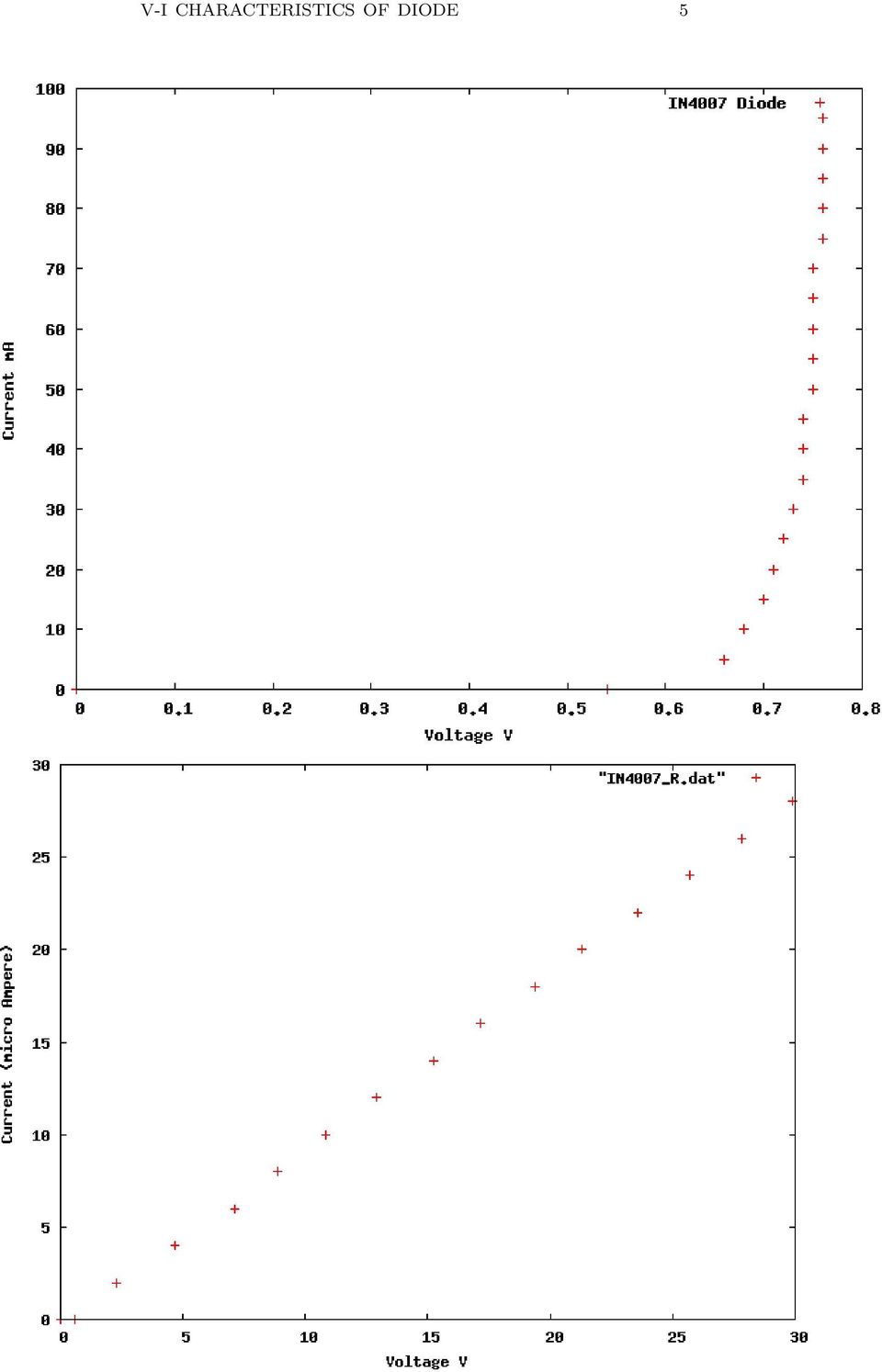
4 4 RAVITEJ UPPU IN4007:The Current is initially Observed at 0.54V. The cut off for this is also around 0.77V. The data tables and graphs are given below. S.No Forward Voltage(V ) Current(mA) Reverse Voltage(V ) Current(µA)

5 V-I CHARACTERISTICS OF DIODE 5
6 6 RAVITEJ UPPU Zener Diode: Here the point in reverse bias where the current starts showing up is 0.52V. The reverse bias of this has a uch gentler slope than the normal diodes as expected. The data tables and graphs are given below. S.No Forward Voltage(V ) Current(mA) Reverse Voltage(V) Current(µA)

7 V-I CHARACTERISTICS OF DIODE 7 A general Comment on my Reverse bias data: We can see that the reverse bias is linear which is because the range of the voltage across the diode in which the data was taken falls just in the range of the linear part of the reverse bias curve. When the experiment was later tried the MicroAmmeter did not work

Lab 1 Diode Characteristics
 Lab 1 Diode Characteristics Purpose The purpose of this lab is to study the characteristics of the diode. Some of the characteristics that will be investigated are the I-V curve and the rectification properties.
Figure 1. Diode circuit model
 Semiconductor Devices Non-linear Devices Diodes Introduction. The diode is two terminal non linear device whose I-V characteristic besides exhibiting non-linear behavior is also polarity dependent. The
LAB IV. SILICON DIODE CHARACTERISTICS
 LAB IV. SILICON DIODE CHARACTERISTICS 1. OBJECTIVE In this lab you are to measure I-V characteristics of rectifier and Zener diodes in both forward and reverse-bias mode, as well as learn to recognize
3. Diodes and Diode Circuits. 3. Diodes and Diode Circuits TLT-8016 Basic Analog Circuits 2005/2006 1
 3. Diodes and Diode Circuits 3. Diodes and Diode Circuits TLT-8016 Basic Analog Circuits 2005/2006 1 3.1 Diode Characteristics Small-Signal Diodes Diode: a semiconductor device, which conduct the current
Diode Circuits. Operating in the Reverse Breakdown region. (Zener Diode)
") Diode Circuits Operating in the Reverse Breakdown region. (Zener Diode) In may applications, operation in the reverse breakdown region is highly desirable. The reverse breakdown voltage is relatively insensitive
Diode Circuits Operating in the Reverse Breakdown region. (Zener Diode) In may applications, operation in the reverse breakdown region is highly desirable. The reverse breakdown voltage is relatively insensitive
Electronics I - Laboratory 1 Diode I/V Characteristics
 Electronics I - Laboratory 1 Diode I/V Characteristics I. Objectives 1. Develop I/V characteristics of a silicon diode. 2. Develop I/V characteristics of a germanium diode. 3. Develop I/V characteristics
Special-Purpose Diodes
 7 Special-Purpose Diodes 7.1 Zener Diode 7.2 Light-Emitting Diode (LED) 7.3 LED Voltage and Current 7.4 Advantages of LED 7.5 Multicolour LEDs 7.6 Applications of LEDs 7.7 Photo-diode 7.8 Photo-diode operation
Lab Report No.1 // Diodes: A Regulated DC Power Supply Omar X. Avelar Omar de la Mora Diego I. Romero
 Instituto Tecnológico y de Estudios Superiores de Occidente (ITESO) Periférico Sur Manuel Gómez Morín 8585, Tlaquepaque, Jalisco, México, C.P. 45090 Analog Electronic Devices (ESI038 / SE047) Dr. Esteban
Diodes and Transistors
 Diodes What do we use diodes for? Diodes and Transistors protect circuits by limiting the voltage (clipping and clamping) turn AC into DC (voltage rectifier) voltage multipliers (e.g. double input voltage)
BJT Characteristics and Amplifiers
 BJT Characteristics and Amplifiers Matthew Beckler [email protected] EE2002 Lab Section 003 April 2, 2006 Abstract As a basic component in amplifier design, the properties of the Bipolar Junction Transistor
THE CURRENT-VOLTAGE CHARACTERISTICS OF AN LED AND A MEASUREMENT OF PLANCK S CONSTANT Physics 258/259
 DSH 2004 THE CURRENT-VOLTAGE CHARACTERISTICS OF AN LED AND A MEASUREMENT OF PLANCK S CONSTANT Physics 258/259 I. INTRODUCTION Max Planck (1858-1947) was an early pioneer in the field of quantum physics.
Fundamentals of Microelectronics
 Fundamentals of Microelectronics CH1 Why Microelectronics? CH2 Basic Physics of Semiconductors CH3 Diode Circuits CH4 Physics of Bipolar Transistors CH5 Bipolar Amplifiers CH6 Physics of MOS Transistors
Lab 1: DC Circuits. Student 1, [email protected] Partner : Student 2, [email protected]
 Lab Date Lab 1: DC Circuits Student 1, [email protected] Partner : Student 2, [email protected] I. Introduction The purpose of this lab is to allow the students to become comfortable with the use of lab
Lecture 3: DC Analysis of Diode Circuits.
 Whites, EE 320 Lecture 3 Page 1 of 10 Lecture 3: DC Analysis of Diode Circuits. We ll now move on to the DC analysis of diode circuits. Applications will be covered in following lectures. Let s consider
ANADOLU UNIVERSITY DEPARTMENT OF ELECTRICAL AND ELECTRONICS ENGINEERING
 ANADOLU UNIVERSITY DEPARTMENT OF ELECTRICAL AND ELECTRONICS ENGINEERING EEM 102 INTRODUCTION TO ELECTRICAL ENGINEERING EXPERIMENT 9: DIODES AND DC POWER SUPPLY OBJECTIVE: To observe how a diode functions
Measuring Silicon and Germanium Band Gaps using Diode Thermometers
 Measuring Silicon and Germanium Band Gaps using Diode Thermometers Haris Amin Department of Physics, Wabash College, Crawfordsville, IN 47933 (Dated: April 11, 2007) This paper reports the band gaps of
Basic Electronics Prof. Dr. Chitralekha Mahanta Department of Electronics and Communication Engineering Indian Institute of Technology, Guwahati
 Basic Electronics Prof. Dr. Chitralekha Mahanta Department of Electronics and Communication Engineering Indian Institute of Technology, Guwahati Module: 2 Bipolar Junction Transistors Lecture-2 Transistor
DIODE CIRCUITS LABORATORY. Fig. 8.1a Fig 8.1b
 DIODE CIRCUITS LABORATORY A solid state diode consists of a junction of either dissimilar semiconductors (pn junction diode) or a metal and a semiconductor (Schottky barrier diode). Regardless of the type,
David L. Senasack June, 2006 Dale Jackson Career Center, Lewisville Texas. The PN Junction
 David L. Senasack June, 2006 Dale Jackson Career Center, Lewisville Texas The PN Junction Objectives: Upon the completion of this unit, the student will be able to; name the two categories of integrated
Lecture-7 Bipolar Junction Transistors (BJT) Part-I Continued
 Part-I Continued") 1 Lecture-7 ipolar Junction Transistors (JT) Part-I ontinued 1. ommon-emitter (E) onfiguration: Most JT circuits employ the common-emitter configuration shown in Fig.1. This is due mainly to the fact that
1 Lecture-7 ipolar Junction Transistors (JT) Part-I ontinued 1. ommon-emitter (E) onfiguration: Most JT circuits employ the common-emitter configuration shown in Fig.1. This is due mainly to the fact that
Experiment #3, Ohm s Law
 Experiment #3, Ohm s Law 1 Purpose Physics 182 - Summer 2013 - Experiment #3 1 To investigate the -oltage, -, characteristics of a carbon resistor at room temperature and at liquid nitrogen temperature,
Chapter 3. Diodes and Applications. Introduction [5], [6]
![Chapter 3. Diodes and Applications. Introduction [5], [6]](/thumbs/40/21801962.jpg "Chapter 3. Diodes and Applications. Introduction [5], [6]") Chapter 3 Diodes and Applications Introduction [5], [6] Diode is the most basic of semiconductor device. It should be noted that the term of diode refers to the basic p-n junction diode. All other diode
Chapter 3 Diodes and Applications Introduction [5], [6] Diode is the most basic of semiconductor device. It should be noted that the term of diode refers to the basic p-n junction diode. All other diode
AN105. Introduction: The Nature of VCRs. Resistance Properties of FETs
 Introduction: The Nature of s A voltage-controlled resistor () may be defined as a three-terminal variable resistor where the resistance value between two of the terminals is controlled by a voltage potential
AC Transport constant current vs. low impedance modes
 Application Note 184-42 AC Transport constant current vs. low impedance modes The AC Transport option offers the user the ability to put the current source in a low output impedance mode. This mode is
Silicon Controlled Rectifiers
 554 20 Principles of Electronics Silicon Controlled Rectifiers 20.1 Silicon Controlled Rectifier (SCR) 20.2 Working of SCR 20.3 Equivalent Circuit of SCR 20.4 Important Terms 20.5 V-I Characteristics of
III. Reaction Kinetics
 III. Reaction Kinetics Lecture 13: Butler-Volmer equation Notes by ChangHoon Lim (and MZB) 1. Interfacial Equilibrium At lecture 11, the reaction rate R for the general Faradaic half-cell reaction was
Diodes. 1 Introduction 1 1.1 Diode equation... 2 1.1.1 Reverse Bias... 2 1.1.2 Forward Bias... 2 1.2 General Diode Specifications...
 Diodes Contents 1 Introduction 1 1.1 Diode equation................................... 2 1.1.1 Reverse Bias................................ 2 1.1.2 Forward Bias................................ 2 1.2 General
Yrd. Doç. Dr. Aytaç Gören
 H2 - AC to DC Yrd. Doç. Dr. Aytaç Gören ELK 2018 - Contents W01 Basic Concepts in Electronics W02 AC to DC Conversion W03 Analysis of DC Circuits W04 Transistors and Applications (H-Bridge) W05 Op Amps
Homework Assignment 03
 Question 1 (2 points each unless noted otherwise) Homework Assignment 03 1. A 9-V dc power supply generates 10 W in a resistor. What peak-to-peak amplitude should an ac source have to generate the same
AMPLIFIERS BJT BJT TRANSISTOR. Types of BJT BJT. devices that increase the voltage, current, or power level
 AMPLFERS Prepared by Engr. JP Timola Reference: Electronic Devices by Floyd devices that increase the voltage, current, or power level have at least three terminals with one controlling the flow between
X-ray Imaging System. X-Ray Circuit. Principles of Imaging Science II (RAD 120) X-ray Imaging System Circuitry
 X-ray Imaging System Circuitry") Principles of Imaging Science II (RAD 120) X-ray Imaging System Circuitry X-ray Imaging System Operating console Set x-ray tube current (quantity) and voltage (quality) Controls line compensation, kvp,
Principles of Imaging Science II (RAD 120) X-ray Imaging System Circuitry X-ray Imaging System Operating console Set x-ray tube current (quantity) and voltage (quality) Controls line compensation, kvp,
Semiconductors, diodes, transistors
 Semiconductors, diodes, transistors (Horst Wahl, QuarkNet presentation, June 2001) Electrical conductivity! Energy bands in solids! Band structure and conductivity Semiconductors! Intrinsic semiconductors!
7. The current voltage characteristic of electric conductors
 KL 7. The current voltage characteristic of electric conductors 7.1 ntroduction The purpose of the present laboratory is to measure the current voltage characteristic of different conducting components.
Bipolar Junction Transistors
 Bipolar Junction Transistors Physical Structure & Symbols NPN Emitter (E) n-type Emitter region p-type Base region n-type Collector region Collector (C) B C Emitter-base junction (EBJ) Base (B) (a) Collector-base
LAB VIII. BIPOLAR JUNCTION TRANSISTOR CHARACTERISTICS
 LAB VIII. BIPOLAR JUNCTION TRANSISTOR CHARACTERISTICS 1. OBJECTIVE In this lab, you will study the DC characteristics of a Bipolar Junction Transistor (BJT). 2. OVERVIEW In this lab, you will inspect the
Operating Manual Ver.1.1
 Silicon, Zener, LED Diode Characteristics Operating Manual Ver.1.1 An ISO 9001 : 2000 company 94-101, Electronic Complex Pardesipura, Indore- 452010, India Tel : 91-731- 2570301/02, 4211100 Fax: 91-731-
Chapter 3 Diode Circuits. 3.1 Ideal Diode 3.2 PN Junction as a Diode 3.3 Applications of Diodes
 Chapter 3 Diode Circuits 3.1 deal Diode 3.2 PN Junction as a Diode 3.3 Applications of Diodes 1 Diode s Application: Cell Phone Charger An important application of diode is chargers. 充 電 器 Diode acts as
Characteristic and use
 . Basic principle A PSD basically consists of a uniform resistive layer formed on one or both surfaces of a high-resistivity semiconductor substrate, and a pair of electrodes formed on both ends of the
Fundamentals of Signature Analysis
 Fundamentals of Signature Analysis An In-depth Overview of Power-off Testing Using Analog Signature Analysis www.huntron.com 1 www.huntron.com 2 Table of Contents SECTION 1. INTRODUCTION... 7 PURPOSE...
Contents. 12. Lot Number 10. 13. Reel Packing Structure 11. 14. Precaution for Use 13. 15. Hazard Substance Analysis 14. 16. Revision History 18
 Rev : 00 ISSUE NO : DATE OF ISSUE : 2009. 04. 10 S P E C I F I CATION MODEL : SLHNNWW629T1S0U0S0 [Rank : (S0), (U0), (S0)] HIGH POWER LED - SUNNIX6 CUSTOMER : CUSTOMER CHECKED CHECKED APPROVED SAMSUNG
Bipolar Junction Transistor Basics
 by Kenneth A. Kuhn Sept. 29, 2001, rev 1 Introduction A bipolar junction transistor (BJT) is a three layer semiconductor device with either NPN or PNP construction. Both constructions have the identical
Fundamental Characteristics of Thyristors
 A1001 Introduction The Thyristor family of semiconductors consists of several very useful devices. The most widely used of this family are silicon controlled rectifiers (SCRs), Triacs, SIDACs, and DIACs.
ENEE 313, Spr 09 Midterm II Solution
 ENEE 313, Spr 09 Midterm II Solution PART I DRIFT AND DIFFUSION, 30 pts 1. We have a silicon sample with non-uniform doping. The sample is 200 µm long: In the figure, L = 200 µm= 0.02 cm. At the x = 0
Crystalline solids. A solid crystal consists of different atoms arranged in a periodic structure.
 Crystalline solids A solid crystal consists of different atoms arranged in a periodic structure. Crystals can be formed via various bonding mechanisms: Ionic bonding Covalent bonding Metallic bonding Van
Unit 7: Electrical devices LO2: Understand electrical sensors and actuators Sensors temperature the thermistor
 Unit 7: Electrical devices LO2: Understand electrical sensors and actuators Sensors temperature the thermistor Instructions and answers for teachers These instructions should accompany the OCR resource
Transistor Biasing. The basic function of transistor is to do amplification. Principles of Electronics
 192 9 Principles of Electronics Transistor Biasing 91 Faithful Amplification 92 Transistor Biasing 93 Inherent Variations of Transistor Parameters 94 Stabilisation 95 Essentials of a Transistor Biasing
Understanding the p-n Junction by Dr. Alistair Sproul Senior Lecturer in Photovoltaics The Key Centre for Photovoltaic Engineering, UNSW
 Understanding the p-n Junction by Dr. Alistair Sproul Senior Lecturer in Photovoltaics The Key Centre for Photovoltaic Engineering, UNSW The p-n junction is the fundamental building block of the electronic
IC Temperature Sensor Provides Thermocouple Cold-Junction Compensation
 IC Temperature Sensor Provides Thermocouple Cold-Junction Compensation INTRODUCTION Due to their low cost and ease of use thermocouples are still a popular means for making temperature measurements up
Unit/Standard Number. High School Graduation Years 2010, 2011 and 2012
 1 Secondary Task List 100 SAFETY 101 Demonstrate an understanding of State and School safety regulations. 102 Practice safety techniques for electronics work. 103 Demonstrate an understanding of proper
The Physics of Energy sources Renewable sources of energy. Solar Energy
 The Physics of Energy sources Renewable sources of energy Solar Energy B. Maffei [email protected] Renewable sources 1 Solar power! There are basically two ways of using directly the radiative
Low Noise, Matched Dual PNP Transistor MAT03
 a FEATURES Dual Matched PNP Transistor Low Offset Voltage: 100 V Max Low Noise: 1 nv/ Hz @ 1 khz Max High Gain: 100 Min High Gain Bandwidth: 190 MHz Typ Tight Gain Matching: 3% Max Excellent Logarithmic
Features. Symbol JEDEC TO-220AB
 Data Sheet June 1999 File Number 2253.2 3A, 5V,.4 Ohm, N-Channel Power MOSFET This is an N-Channel enhancement mode silicon gate power field effect transistor designed for applications such as switching
Amplifier Teaching Aid
 Amplifier Teaching Aid Table of Contents Amplifier Teaching Aid...1 Preface...1 Introduction...1 Lesson 1 Semiconductor Review...2 Lesson Plan...2 Worksheet No. 1...7 Experiment No. 1...7 Lesson 2 Bipolar
Efficient and reliable operation of LED lighting is dependent on the right choice of current-limiting resistor
 Efficient and reliable operation of LED lighting is dependent on the right choice of current-limiting resistor Phil Ebbert, VP of Engineering, Riedon Inc. Introduction Not all resistors are the same and
FEATURE ARTICLE. Figure 1: Current vs. Forward Voltage Curves for Silicon Schottky Diodes with High, Medium, Low and ZBD Barrier Heights
 PAGE 1 FEBRUARY 2009 Schottky Diodes by Rick Cory, Skyworks Solutions, Inc. Introduction Schottky diodes have been used for several decades as the key elements in frequency mixer and RF power detector
Resistance, Ohm s Law, and the Temperature of a Light Bulb Filament
 Resistance, Ohm s Law, and the Temperature of a Light Bulb Filament Name Partner Date Introduction Carbon resistors are the kind typically used in wiring circuits. They are made from a small cylinder of
Project 2B Building a Solar Cell (2): Solar Cell Performance
: Solar Cell Performance") April. 15, 2010 Due April. 29, 2010 Project 2B Building a Solar Cell (2): Solar Cell Performance Objective: In this project we are going to experimentally measure the I-V characteristics, energy conversion
April. 15, 2010 Due April. 29, 2010 Project 2B Building a Solar Cell (2): Solar Cell Performance Objective: In this project we are going to experimentally measure the I-V characteristics, energy conversion
LM135-LM235-LM335. Precision temperature sensors. Features. Description
 Precision temperature sensors Features Directly calibrated in K 1 C initial accuracy Operates from 450µA to 5mA Less than 1Ω dynamic impedance TO-92 (Plastic package) Description The LM135, LM235, LM335
Solid-State Physics: The Theory of Semiconductors (Ch. 10.6-10.8) SteveSekula, 30 March 2010 (created 29 March 2010)
 SteveSekula, 30 March 2010 (created 29 March 2010)") Modern Physics (PHY 3305) Lecture Notes Modern Physics (PHY 3305) Lecture Notes Solid-State Physics: The Theory of Semiconductors (Ch. 10.6-10.8) SteveSekula, 30 March 2010 (created 29 March 2010) Review
Modern Physics (PHY 3305) Lecture Notes Modern Physics (PHY 3305) Lecture Notes Solid-State Physics: The Theory of Semiconductors (Ch. 10.6-10.8) SteveSekula, 30 March 2010 (created 29 March 2010) Review
Power Supplies. 1.0 Power Supply Basics. www.learnabout-electronics.org. Module
 Module 1 www.learnabout-electronics.org Power Supplies 1.0 Power Supply Basics What you ll learn in Module 1 Section 1.0 Power Supply Basics. Basic functions of a power supply. Safety aspects of working
Features: High reliability. Very sharp reverse characteristic. Zener voltage 3.3V to 12V. V z -tolerance ±5%.
 Features: High reliability. Very sharp reverse characteristic. Zener voltage 3.3V to 12V. V z -tolerance ±5%. Applications: Voltage stabilization. Absolute Maximum Ratings Parameter Test Conditions Symbol
Planar PIN diode in a SOD323 very small plastic SMD package.
 Rev. 8 12 May 2015 Product data sheet 1. Product profile 1.1 General description Planar PIN diode in a SOD323 very small plastic SMD package. 1.2 Features and benefits High voltage, current controlled
Field Effect Transistors
 506 19 Principles of Electronics Field Effect Transistors 191 Types of Field Effect Transistors 193 Principle and Working of JFET 195 Importance of JFET 197 JFET as an Amplifier 199 Salient Features of
Solid State Detectors = Semi-Conductor based Detectors
 Solid State Detectors = Semi-Conductor based Detectors Materials and their properties Energy bands and electronic structure Charge transport and conductivity Boundaries: the p-n junction Charge collection
Application Notes FREQUENCY LINEAR TUNING VARACTORS FREQUENCY LINEAR TUNING VARACTORS THE DEFINITION OF S (RELATIVE SENSITIVITY)
") FREQUENY LINEAR TUNING VARATORS FREQUENY LINEAR TUNING VARATORS For several decades variable capacitance diodes (varactors) have been used as tuning capacitors in high frequency circuits. Most of these
FREQUENY LINEAR TUNING VARATORS FREQUENY LINEAR TUNING VARATORS For several decades variable capacitance diodes (varactors) have been used as tuning capacitors in high frequency circuits. Most of these
IR Edixeon Emitter. 1W Edixeon
 High Power LED 1W Edixeon IR Edixeon Emitter Date:2006/06/01 Version:2.0 Device No. : 3-RD-01-E0009 Believe SRL Via Lago di Trasimeno, 21 - Schio (VI) - Italy TEL: +39/0445/579035 FAX: +39/0445/575708
Transistors. NPN Bipolar Junction Transistor
 Transistors They are unidirectional current carrying devices with capability to control the current flowing through them The switch current can be controlled by either current or voltage ipolar Junction
Data Sheet. HLCP-A100 LED Light Bars
 HLCP-A100 LED Light Bars Data Sheet HLCP-A100/-B100/-C100/D100/-E100/-F100/-G100/-H100 HLMP-2300/-2350/-2400/-2450/-2500/-2550 HLMP-2600/-2620/-2635/-2655/-2670/-2685 HLMP-2700/-2720/-2735/-2755/-2770/-2785
BASIC ELECTRONICS TRANSISTOR THEORY. December 2011
 AM 5-204 BASIC ELECTRONICS TRANSISTOR THEORY December 2011 DISTRIBUTION RESTRICTION: Approved for Public Release. Distribution is unlimited. DEPARTMENT OF THE ARMY MILITARY AUXILIARY RADIO SYSTEM FORT
Efficiency of a Light Emitting Diode
 PHYSICS THROUGH TEACHING LABORATORY VII Efficiency of a Light Emitting Diode RAJESH B. KHAPARDE AND SMITHA PUTHIYADAN Homi Bhabha Centre for Science Education Tata Institute of Fundamental Research V.
LABORATORY 10 TIME AVERAGES, RMS VALUES AND THE BRIDGE RECTIFIER. Bridge Rectifier
 LABORATORY 10 TIME AVERAGES, RMS VALUES AND THE BRIDGE RECTIFIER Full-wave Rectification: Bridge Rectifier For many electronic circuits, DC supply voltages are required but only AC voltages are available.
Supplement Reading on Diode Circuits. http://www.inst.eecs.berkeley.edu/ edu/~ee40/fa09/handouts/ee40_mos_circuit.pdf
 EE40 Lec 18 Diode Circuits Reading: Chap. 10 of Hambley Supplement Reading on Diode Circuits http://www.inst.eecs.berkeley.edu/ edu/~ee40/fa09/handouts/ee40_mos_circuit.pdf Slide 1 Diodes Circuits Load
The FET Constant-Current Source/Limiter. I D = ( V DS )(g oss ) (3) R L. g oss. where g oss = g oss (5) when V GS = 0 (6)
(g oss ) (3) R L. g oss. where g oss = g oss (5) when V GS = 0 (6)") The FET Constant-Current ource/limiter Introduction The combination of low associated operating voltage and high output impedance makes the FET attractive as a constant-current source. An adjustable-current
The FET Constant-Current ource/limiter Introduction The combination of low associated operating voltage and high output impedance makes the FET attractive as a constant-current source. An adjustable-current
Field-Effect (FET) transistors
 transistors") Field-Effect (FET) transistors References: Hayes & Horowitz (pp 142-162 and 244-266), Rizzoni (chapters 8 & 9) In a field-effect transistor (FET), the width of a conducting channel in a semiconductor and,
Field-Effect (FET) transistors References: Hayes & Horowitz (pp 142-162 and 244-266), Rizzoni (chapters 8 & 9) In a field-effect transistor (FET), the width of a conducting channel in a semiconductor and,
The 2N3393 Bipolar Junction Transistor
 The 2N3393 Bipolar Junction Transistor Common-Emitter Amplifier Aaron Prust Abstract The bipolar junction transistor (BJT) is a non-linear electronic device which can be used for amplification and switching.
School of Engineering Department of Electrical and Computer Engineering
 1 School of Engineering Department of Electrical and Computer Engineering 332:223 Principles of Electrical Engineering I Laboratory Experiment #4 Title: Operational Amplifiers 1 Introduction Objectives
Plots, Curve-Fitting, and Data Modeling in Microsoft Excel
 Plots, Curve-Fitting, and Data Modeling in Microsoft Excel This handout offers some tips on making nice plots of data collected in your lab experiments, as well as instruction on how to use the built-in
Physics 221 Experiment 5: Magnetic Fields
 Physics 221 Experiment 5: Magnetic Fields August 25, 2007 ntroduction This experiment will examine the properties of magnetic fields. Magnetic fields can be created in a variety of ways, and are also found
High Resolution Spatial Electroluminescence Imaging of Photovoltaic Modules
 High Resolution Spatial Electroluminescence Imaging of Photovoltaic Modules Abstract J.L. Crozier, E.E. van Dyk, F.J. Vorster Nelson Mandela Metropolitan University Electroluminescence (EL) is a useful
Semiconductor Diode. It has already been discussed in the previous chapter that a pn junction conducts current easily. Principles of Electronics
 76 6 Principles of Electronics Semiconductor Diode 6.1 Semiconductor Diode 6.3 Resistance of Crystal Diode 6.5 Crystal Diode Equivalent Circuits 6.7 Crystal Diode Rectifiers 6.9 Output Frequency of Half-Wave
TRANSISTOR/DIODE TESTER
 TRANSISTOR/DIODE TESTER MODEL DT-100 Lesson Manual ELENCO Copyright 2012, 1988 REV-G 753115 Elenco Electronics, Inc. Revised 2012 FEATURES Diode Mode: 1. Checks all types of diodes - germanium, silicon,
Precision Diode Rectifiers
 by Kenneth A. Kuhn March 21, 2013 Precision half-wave rectifiers An operational amplifier can be used to linearize a non-linear function such as the transfer function of a semiconductor diode. The classic
A Comparison of Various Bipolar Transistor Biasing Circuits Application Note 1293
 A omparison of Various Bipolar Transistor Biasing ircuits Application Note 1293 Introduction The bipolar junction transistor (BJT) is quite often used as a low noise amplifier in cellular, PS, and pager
Lecture - 4 Diode Rectifier Circuits
 Basic Electronics (Module 1 Semiconductor Diodes) Dr. Chitralekha Mahanta Department of Electronics and Communication Engineering Indian Institute of Technology, Guwahati Lecture - 4 Diode Rectifier Circuits
Lab E1: Introduction to Circuits
 E1.1 Lab E1: Introduction to Circuits The purpose of the this lab is to introduce you to some basic instrumentation used in electrical circuits. You will learn to use a DC power supply, a digital multimeter
NTE923 & NTE923D Integrated Circuit Precision Voltage Regulator
 NTE923 & NTE923D Integrated Circuit Precision Voltage Regulator Description: The NTE923 and NTE923D are voltage regulators designed primarily for series regulator applications. By themselves, these devices
Fig. 1 Analogue Multimeter Fig.2 Digital Multimeter
 ELECTRICAL INSTRUMENT AND MEASUREMENT Electrical measuring instruments are devices used to measure electrical quantities such as electric current, voltage, resistance, electrical power and energy. MULTIMETERS
BIPOLAR JUNCTION TRANSISTORS
 CHAPTER 3 BIPOLAR JUNCTION TRANSISTORS A bipolar junction transistor, BJT, is a single piece of silicon with two back-to-back P-N junctions. However, it cannot be made with two independent back-to-back
CALIBRATION OF A THERMISTOR THERMOMETER (version = fall 2001)
") CALIBRATION OF A THERMISTOR THERMOMETER (version = fall 2001) I. Introduction Calibration experiments or procedures are fairly common in laboratory work which involves any type of instrumentation. Calibration
CALIBRATION OF A THERMISTOR THERMOMETER (version = fall 2001) I. Introduction Calibration experiments or procedures are fairly common in laboratory work which involves any type of instrumentation. Calibration
LAB VII. BIPOLAR JUNCTION TRANSISTOR CHARACTERISTICS
 LAB VII. BIPOLAR JUNCTION TRANSISTOR CHARACTERISTICS 1. OBJECTIVE In this lab, you will study the DC characteristics of a Bipolar Junction Transistor (BJT). 2. OVERVIEW You need to first identify the physical
Electronic Devices and Circuit Theory
 Instructor s Resource Manual to accompany Electronic Devices and Circuit Theory Tenth Edition Robert L. Boylestad Louis Nashelsky Upper Saddle River, New Jersey Columbus, Ohio Copyright 2009 by Pearson
Transistor Amplifiers
 Physics 3330 Experiment #7 Fall 1999 Transistor Amplifiers Purpose The aim of this experiment is to develop a bipolar transistor amplifier with a voltage gain of minus 25. The amplifier must accept input
Hello and Welcome to this presentation on LED Basics. In this presentation we will look at a few topics in semiconductor lighting such as light
 Hello and Welcome to this presentation on LED Basics. In this presentation we will look at a few topics in semiconductor lighting such as light generation from a semiconductor material, LED chip technology,
Data Sheet. Nationstar LED
 Data Sheet Nationstar LED 1 Table of Contents General Informations:... 3 Electrical and Flux Characteristics... 3 Color Wavelength Diagram:... 6 Mechanical Dimensions:... 7 Electrical Connection:... 7
Solar Cell Parameters and Equivalent Circuit
 9 Solar Cell Parameters and Equivalent Circuit 9.1 External solar cell parameters The main parameters that are used to characterise the performance of solar cells are the peak power P max, the short-circuit
Properties of electrical signals
 DC Voltage Component (Average voltage) Properties of electrical signals v(t) = V DC + v ac (t) V DC is the voltage value displayed on a DC voltmeter Triangular waveform DC component Half-wave rectifier
Analog Optical Isolators VACTROLS
 Analog Optical Isolators VACTROLS What Are Analog Optical Isolators? PerkinElmer Optoelectronics has been a leading manufacturer of analog optical isolators for over twenty years and makes a broad range
Gamma and X-Ray Detection
 Gamma and X-Ray Detection DETECTOR OVERVIEW The kinds of detectors commonly used can be categorized as: a. Gas-filled Detectors b. Scintillation Detectors c. Semiconductor Detectors The choice of a particular
Chapter 22 Further Electronics
 hapter 22 Further Electronics washing machine has a delay on the door opening after a cycle of washing. Part of this circuit is shown below. s the cycle ends, switch S closes. t this stage the capacitor