Σ _. Feedback Amplifiers: One and Two Pole cases. Negative Feedback:
|
|
|
- Bridget Greene
- 9 years ago
- Views:
Transcription
1

2 Feedback Amplifiers: One and Two Pole cases Negative Feedback: Σ _ a f There must be 180 o phase shift somewhere in the loop. This is often provided by an inverting amplifier or by use of a differential amplifier. Closed Loop Gain: When a >> 1, then a A= 1 + af a 1 A = af f This is a very useful approximation. The product af occurs frequently: Loop Gain or Loop Transmission T = af a f

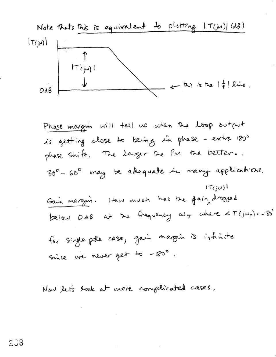
3 At low frequencies, the amplifier does not produce any excess phase shift. The feedback block is a passive network. But, all amplifiers contain poles. Beyond some frequency there will be excess phase shift and this will affect the stability of the closed loop system. Frequency Response Using negative feedback, we have chosen to exchange gain a for improved performance Since A = 1/f, there is little variation of closed loop gain with a. Gain is determined by the passive network f But as frequency increases, we run the possibility of Instability Gain peaking Ringing and overshoot in the transient response We will develop methods for evaluation and compensation of these problems. Bandwidth of feedback amplifiers: Single Pole case Assume the amplifier has a frequency dependent transfer function as () as () As () = = 1 + as ( ) f 1 + Ts ( ) and ao as () = 1 s/ p where p 1 is on the negative real axis of the s plane. 1

4 With substitution, it can be shown that: a 1 As () = + + )] o 1 aof 1 s/[ p1(1 aof We see the low frequency gain with feedback as the first term followed by a bandwidth term. The 3dB bandwidth has been expanded by the factor 1 + a o f = 1 + T o. S - plane x p 1 (1+To) x p 1 Bode Plot 20 log a(jω) x 20 log A(jω) = 20 log (1/f) a(jω) 0-90 p 1 p 1 (1+To) -180
 x p 1 Bode Plot 20 log a(jω) x 20 log A(jω) = 20 log (1/f) a(jω)")
5 Note that the separation between a and A, labeled as x, x= 20log( a( jω) ) 20log(1/ f) = 20log( a( jω) f ) = 20log( T( jω)) Therefore, a plot of T(jω) in db would be the equivalent of the plot above with the vertical scale shifted to show 1/f at 0 db. We see from the single pole case, the maximum excess phase shift that the amplifier can produce is 90 degrees. Stability condition: If T(jω) > 1 at a frequency where T(jω) = -180 o, then the amplifier is unstable. This is the opposite of the Barkhousen criteria used to judge oscillation with positive feedback. In fact, a round trip 360 degrees (180 for the inverting amplifier at low frequency plus the excess 180 due to poles) will produce positive feedback and oscillations. This is a feedback based definition. The traditional methods using T(jω) Bode Plots Nyquist diagram Root locus plots can also be used to determine stability. I find the Bode method most useful for providing design insight. To see how this may work, first define what is meant by PHASE MARGIN in the context of feedback systems.
 will produce positive feedback and oscillations.")
6

7
8

9
10

11

12

13

14

15
16

17
18

19

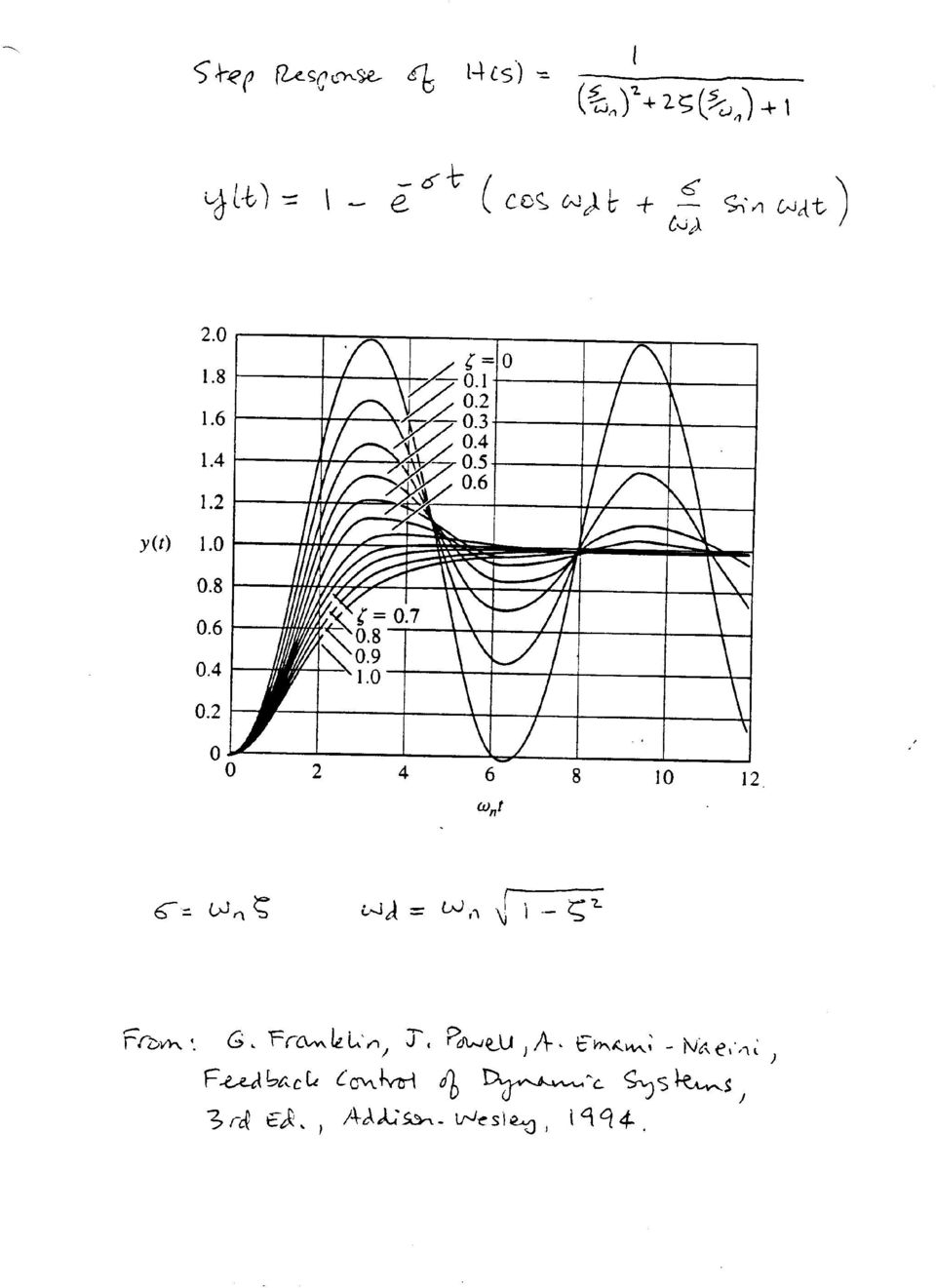
20 Two pole frequency and step response. Low pass. No zeros. Frequency Response 3 db ω3db = ωn 1 2ζ + 2 4ζ + 4ζ bandwidth Gain 1 M P = ζ < peaking 2 2ζ 1 ζ Step Response Risetime (10-90%) tr = 2.2/ ω3db Overshoot πζ (%) 100 exp 2 1 ζ Ringing 2 ωd = ωn 1 ζ frequency Settling time 1 % ts ζω = ln 100 n
 100 exp 2 1 ζ Ringing 2 ωd = ωn 1 ζ frequency")
21 Zero in Loop Gain, T(s). There will be some cases where we will want to add a zero to the loop gain T(s). How does this zero affect the transient response? Let s locate the zero frequency relative to the real part of the closed loop pole location using α as a proportionality factor s = - αζω n. H() s = ( s ) 2 ( s αζ ) + 1 ω + 2 ζs/ ω + 1 n A large α will place the zero far to the left of the poles. Let s normalize ωn = 1. Then, n H() s = s s αζ ζ s + 1 Split this into 2 equations. 1 1 s H() s = s + 2ζs+ 1 αζ s + 2ζs+ 1 We see that the second term is the derivative of the first term (first term is multiplied by s times a coefficient). This can produce a bump in the step response. See the next figure from G. Franklin, et al, Feedback Control of Dynamic Systems, 3 rd edition, Addison- Wesley, Ho(s) is the first term; Hd(s) is the derivative term. We see that if α is close to 1, we get a big increase in the overshoot.
22 Ref. Franklin, op.cit.
23
24
25 Compensation Question: What happens when the phase margin is too small or negative for the particular value of feedback required for an application. The transient response will ring, gain will peak, or possibly oscillation. If you are building an oscillator, that might be good, but if you intended it as an amplifier then you must modify its frequency response to make it useable. Compensation is a technique that accomplished this, albeit at the expense of bandwidth. Many techniques are available: Add a dominant pole Move a dominant pole Miller compensation Add a zero to the closed loop gain 1. Dominant Pole Compensation Add another pole that is much lower in frequency than the existing poles of the amplifier or system. This is the least efficient of the compensation techniques but may be the easiest to implement. Reduces bandwidth, but increases the phase margin at the crossover frequency. T is reduced over the useful bandwidth, Thus, some of the feedback benefits are sacrificed in order to obtain better stability Extrapolate back from the crossover frequency at 20 db/decade The frequency, P D, where the line intersects the open loop gain Ao is the new dominant pole frequency. In this case, T(jω) = 1 at ω = p 1 45 o phase margin Note that we are assuming that the other poles are not affected by the new dominant pole. This is not always the case, and computer simulation will be needed to optimize the design. Nevertheless, this simple method will usually help you get started with a solution that will generally work even though not optimum.
26
27 For example, you could add C to produce a dominant pole at p D 1 = 2 CR ( R ) L1 i2 This approach may require a large compensating capacitor, C. Let s look at some better approaches.
28 2. Reduce p1 instead of adding yet another pole. Retains more bandwidth Requires less C to shift an existing pole p2 and p3 may even be moved up to a higher frequency Move p 1 to p 1 'such that the new crossover frequency is at p 2 >> p 1 From Gray, Hurst, Lewis and Meyer, Analysis and Design of Analog Integrated Circuits, 4th ed., J. Wiley, 2001.
29 3. What if we reduce p1 and increase p2 at the same time! Big bandwidth improvement Phase margin improves without sacrifice of bandwidth Pushes out crossover frequency MILLER COMPENSATION The first and second pole frequencies can be estimated by the method of time constants. Assuming that K Hs () = 2 as + as+ a then, 1 p1 a 1 and a p 1 2 a 2
30
31
32
33
34
35 Alternatively, if we assume that the non-dominant pole is at a very high frequency CF behaves like a short The current source just looks like: so, V 1 Z = 1 = i 1 g m p 2 gm C + C π L A much easier way to see how the pole splitting comes about...
36 Compensation by adding a zero in the feedback path In wideband amplifier applications, adding dominant poles or Miller compensation is undesirable due to the loss in bandwidth that is incurred. In some cases, it is possible to add a zero to the feedback path by adding a frequency dependent component. The zero bends the root locus and improves the bandwidth as well as the damping of the amplifier. Adding a zero to f(s) will put a zero in T(s) and thus affects the root locus. But, it doesn t add a zero to A(s). Thus, it doesn t produce the overshoot problems that a zero in the forward path would cause. The forward path zero would show up in the closed loop transfer function. If we consider the overall gain with feedback as: a( s) A( s) = 1 + a( s) f ( s) and a(s) = Na(s)/Da(s) and f(s) = Nf(s)/Df(s) Then, A( s) = D f a ( s) D a o N a ( s) D ( s) + T N o f ( s) a ( s) N f ( s) Here we see that the zero Nf(s) shows up in the denominator of A(s) multiplied by To. And, typically for this type of compensation, the pole contributed by the f(s) block is at a much higher frequency than the zero. Referring to the circular root locus sketched on the next page, we see that the zero bends the poles away from the jω axis. This increases ζ, improving damping, and also improves bandwidth.
37 The root locus will travel around the zero in a circle if there are no other poles to the left. The poles will terminate at large T on zeros at ω 2 and at infinity. ω 2 ω 1 We can appreciate the effectiveness of this by comparing with the two pole low pass case where the poles remain at the same distance from the jω axis as T is increased. ω 1 4 K 1 2 ω V 1 ω 1 ω 1 /2
38 So, how do you implement a zero in the feedback path? We need to find f(s). With SHUNT at input, currents are summed With SERIES output, current is sampled f() s i RE 1+ srfc F i R RR E+ R F 1+ sc E F F R E+ R F = 1 = 2 Zero: 1 R C F F Pole: 1 R E CFR RE + RF F Typically, the pole frequency is much higher than the zero, so it does not bend the root locus very much.
39 Next, let s look at the phase margin. Recall that This blows up when a0 A( jω) = 1 + T( jω) T( jω) = 1e jπ = 1 Thus, even if the phase reaches -180 degrees, if the magnitude is not equal to 1, we do not have instability.
Understanding Poles and Zeros
 MASSACHUSETTS INSTITUTE OF TECHNOLOGY DEPARTMENT OF MECHANICAL ENGINEERING 2.14 Analysis and Design of Feedback Control Systems Understanding Poles and Zeros 1 System Poles and Zeros The transfer function
Controller Design in Frequency Domain
 ECSE 4440 Control System Engineering Fall 2001 Project 3 Controller Design in Frequency Domain TA 1. Abstract 2. Introduction 3. Controller design in Frequency domain 4. Experiment 5. Colclusion 1. Abstract
Positive Feedback and Oscillators
 Physics 3330 Experiment #6 Fall 1999 Positive Feedback and Oscillators Purpose In this experiment we will study how spontaneous oscillations may be caused by positive feedback. You will construct an active
ECE 3510 Final given: Spring 11
 ECE 50 Final given: Spring This part of the exam is Closed book, Closed notes, No Calculator.. ( pts) For each of the time-domain signals shown, draw the poles of the signal's Laplace transform on the
Engineering Sciences 22 Systems Summer 2004
 Engineering Sciences 22 Systems Summer 24 BODE PLOTS A Bode plot is a standard format for plotting frequency response of LTI systems. Becoming familiar with this format is useful because: 1. It is a standard
Chapter 9: Controller design
 Chapter 9. Controller Design 9.1. Introduction 9.2. Effect of negative feedback on the network transfer functions 9.2.1. Feedback reduces the transfer function from disturbances to the output 9.2.2. Feedback
MATLAB Control System Toolbox Root Locus Design GUI
 MATLAB Control System Toolbox Root Locus Design GUI MATLAB Control System Toolbox contains two Root Locus design GUI, sisotool and rltool. These are two interactive design tools for the analysis and design
S-DOMAIN ANALYSIS: POLES, ZEROS, AND BODE PLOTS
 S-DOMAIN ANAYSIS: POES, ZEROS, AND BODE POTS The main objectiveis to find amplifier voltage gain as a transfer function of the complex frequency s. In this s-domain analysis a capacitance С is replaced
Electronics for Analog Signal Processing - II Prof. K. Radhakrishna Rao Department of Electrical Engineering Indian Institute of Technology Madras
 Electronics for Analog Signal Processing - II Prof. K. Radhakrishna Rao Department of Electrical Engineering Indian Institute of Technology Madras Lecture - 18 Wideband (Video) Amplifiers In the last class,
EE 402 RECITATION #13 REPORT
 MIDDLE EAST TECHNICAL UNIVERSITY EE 402 RECITATION #13 REPORT LEAD-LAG COMPENSATOR DESIGN F. Kağan İPEK Utku KIRAN Ç. Berkan Şahin 5/16/2013 Contents INTRODUCTION... 3 MODELLING... 3 OBTAINING PTF of OPEN
UNIVERSITY OF CALIFORNIA AT BERKELEY College of Engineering Department of Electrical Engineering and Computer Sciences. EE105 Lab Experiments
 UNIVERSITY OF CALIFORNIA AT BERKELEY College of Engineering Department of Electrical Engineering and Computer Sciences EE15 Lab Experiments Bode Plot Tutorial Contents 1 Introduction 1 2 Bode Plots Basics
Root Locus. E(s) K. R(s) C(s) 1 s(s+a) Consider the closed loop transfer function:
 K. R(s) C(s) 1 s(s+a) Consider the closed loop transfer function:") Consider the closed loop transfer function: Root Locus R(s) + - E(s) K 1 s(s+a) C(s) How do the poles of the closed-loop system change as a function of the gain K? The closed-loop transfer function is:
Consider the closed loop transfer function: Root Locus R(s) + - E(s) K 1 s(s+a) C(s) How do the poles of the closed-loop system change as a function of the gain K? The closed-loop transfer function is:
Fully Differential CMOS Amplifier
 ECE 511 Analog Electronics Term Project Fully Differential CMOS Amplifier Saket Vora 6 December 2006 Dr. Kevin Gard NC State University 1 Introduction In this project, a fully differential CMOS operational
Laboratory 4: Feedback and Compensation
 Laboratory 4: Feedback and Compensation To be performed during Week 9 (Oct. 20-24) and Week 10 (Oct. 27-31) Due Week 11 (Nov. 3-7) 1 Pre-Lab This Pre-Lab should be completed before attending your regular
The basic cascode amplifier consists of an input common-emitter (CE) configuration driving an output common-base (CB), as shown above.
 configuration driving an output common-base (CB), as shown above.") Cascode Amplifiers by Dennis L. Feucht Two-transistor combinations, such as the Darlington configuration, provide advantages over single-transistor amplifier stages. Another two-transistor combination
Cascode Amplifiers by Dennis L. Feucht Two-transistor combinations, such as the Darlington configuration, provide advantages over single-transistor amplifier stages. Another two-transistor combination
Understanding Power Impedance Supply for Optimum Decoupling
 Introduction Noise in power supplies is not only caused by the power supply itself, but also the load s interaction with the power supply (i.e. dynamic loads, switching, etc.). To lower load induced noise,
Designing Stable Compensation Networks for Single Phase Voltage Mode Buck Regulators
 Designing Stable Compensation Networks for Single Phase Voltage Mode Buck Regulators Technical Brief December 3 TB47. Author: Doug Mattingly Assumptions This Technical Brief makes the following assumptions:.
30. Bode Plots. Introduction
 0. Bode Plots Introduction Each of the circuits in this problem set is represented by a magnitude Bode plot. The network function provides a connection between the Bode plot and the circuit. To solve these
Bode Diagrams of Transfer Functions and Impedances ECEN 2260 Supplementary Notes R. W. Erickson
 Bode Diagrams of Transfer Functions and Impedances ECEN 2260 Supplementary Notes. W. Erickson In the design of a signal processing network, control system, or other analog system, it is usually necessary
Design of a TL431-Based Controller for a Flyback Converter
 Design of a TL431-Based Controller for a Flyback Converter Dr. John Schönberger Plexim GmbH Technoparkstrasse 1 8005 Zürich 1 Introduction The TL431 is a reference voltage source that is commonly used
Chapter 3 AUTOMATIC VOLTAGE CONTROL
 Chapter 3 AUTOMATIC VOLTAGE CONTROL . INTRODUCTION TO EXCITATION SYSTEM The basic function of an excitation system is to provide necessary direct current to the field winding of the synchronous generator.
APPLICATION BULLETIN
 APPLICATION BULLETIN Mailing Address: PO Box 11400, Tucson, AZ 85734 Street Address: 6730 S. Tucson Blvd., Tucson, AZ 85706 Tel: (520) 746-1111 Telex: 066-6491 FAX (520) 889-1510 Product Info: (800) 548-6132
ADS Tutorial Stability and Gain Circles ECE145A/218A
 ADS Tutorial Stability and Gain Circles ECE145A/218A The examples in this tutorial can be downloaded from xanadu.ece.ucsb.edu/~long/ece145a as the file: stab_gain.zap The first step in designing the amplifier
Basic Op Amp Circuits
 Basic Op Amp ircuits Manuel Toledo INEL 5205 Instrumentation August 3, 2008 Introduction The operational amplifier (op amp or OA for short) is perhaps the most important building block for the design of
Part IB Paper 6: Information Engineering LINEAR SYSTEMS AND CONTROL Dr Glenn Vinnicombe HANDOUT 3. Stability and pole locations.
 Part IB Paper 6: Information Engineering LINEAR SYSTEMS AND CONTROL Dr Glenn Vinnicombe HANDOUT 3 Stability and pole locations asymptotically stable marginally stable unstable Imag(s) repeated poles +
Programmable-Gain Transimpedance Amplifiers Maximize Dynamic Range in Spectroscopy Systems
 Programmable-Gain Transimpedance Amplifiers Maximize Dynamic Range in Spectroscopy Systems PHOTODIODE VOLTAGE SHORT-CIRCUIT PHOTODIODE SHORT- CIRCUIT VOLTAGE 0mV DARK ark By Luis Orozco Introduction Precision
Nodal and Loop Analysis
 Nodal and Loop Analysis The process of analyzing circuits can sometimes be a difficult task to do. Examining a circuit with the node or loop methods can reduce the amount of time required to get important
System Modeling and Control for Mechanical Engineers
 Session 1655 System Modeling and Control for Mechanical Engineers Hugh Jack, Associate Professor Padnos School of Engineering Grand Valley State University Grand Rapids, MI email: [email protected] Abstract
First, we show how to use known design specifications to determine filter order and 3dB cut-off
 Butterworth Low-Pass Filters In this article, we describe the commonly-used, n th -order Butterworth low-pass filter. First, we show how to use known design specifications to determine filter order and
Using the Impedance Method
 Using the Impedance Method The impedance method allows us to completely eliminate the differential equation approach for the determination of the response of circuits. In fact the impedance method even
Testing a power supply for line and load transients
 Testing a power supply for line and load transients Power-supply specifications for line and load transients describe the response of a power supply to abrupt changes in line voltage and load current.
Series and Parallel Resistive Circuits
 Series and Parallel Resistive Circuits The configuration of circuit elements clearly affects the behaviour of a circuit. Resistors connected in series or in parallel are very common in a circuit and act
Second Order Systems
 Second Order Systems Second Order Equations Standard Form G () s = τ s K + ζτs + 1 K = Gain τ = Natural Period of Oscillation ζ = Damping Factor (zeta) Note: this has to be 1.0!!! Corresponding Differential
Introduction to Bode Plot
 Introduction to Bode Plot 2 plots both have logarithm of frequency on x-axis o y-axis magnitude of transfer function, H(s), in db o y-axis phase angle The plot can be used to interpret how the input affects
Technical Note #3. Error Amplifier Design and Applications. Introduction
 Technical Note #3 Error Amplifier Design and Applications Introduction All regulating power supplies require some sort of closed-loop control to force the output to match the desired value. Both digital
Op-Amp Simulation EE/CS 5720/6720. Read Chapter 5 in Johns & Martin before you begin this assignment.
 Op-Amp Simulation EE/CS 5720/6720 Read Chapter 5 in Johns & Martin before you begin this assignment. This assignment will take you through the simulation and basic characterization of a simple operational
2.161 Signal Processing: Continuous and Discrete Fall 2008
 MT OpenCourseWare http://ocw.mit.edu.6 Signal Processing: Continuous and Discrete Fall 00 For information about citing these materials or our Terms of Use, visit: http://ocw.mit.edu/terms. MASSACHUSETTS
Fig. 1 :Block diagram symbol of the operational amplifier. Characteristics ideal op-amp real op-amp
 Experiment: General Description An operational amplifier (op-amp) is defined to be a high gain differential amplifier. When using the op-amp with other mainly passive elements, op-amp circuits with various
Lab 7: Operational Amplifiers Part I
 Lab 7: Operational Amplifiers Part I Objectives The objective of this lab is to study operational amplifier (op amp) and its applications. We will be simulating and building some basic op amp circuits,
3.2 Sources, Sinks, Saddles, and Spirals
 3.2. Sources, Sinks, Saddles, and Spirals 6 3.2 Sources, Sinks, Saddles, and Spirals The pictures in this section show solutions to Ay 00 C By 0 C Cy D 0. These are linear equations with constant coefficients
Since any real component also has loss due to the resistive component, the average power dissipated is 2 2R
 Quality factor, Q Reactive components such as capacitors and inductors are often described with a figure of merit called Q. While it can be defined in many ways, it s most fundamental description is: Q
Application Report SLVA051
 Application Report November 998 Mixed-Signal Products SLVA05 ltage Feedback Vs Current Feedback Op Amps Application Report James Karki Literature Number: SLVA05 November 998 Printed on Recycled Paper IMPORTANT
CHAPTER 6 Frequency Response, Bode Plots, and Resonance
 ELECTRICAL CHAPTER 6 Frequency Response, Bode Plots, and Resonance 1. State the fundamental concepts of Fourier analysis. 2. Determine the output of a filter for a given input consisting of sinusoidal
Lecture 9. Poles, Zeros & Filters (Lathi 4.10) Effects of Poles & Zeros on Frequency Response (1) Effects of Poles & Zeros on Frequency Response (3)
 Effects of Poles & Zeros on Frequency Response (1) Effects of Poles & Zeros on Frequency Response (3)") Effects of Poles & Zeros on Frequency Response (1) Consider a general system transfer function: zeros at z1, z2,..., zn Lecture 9 Poles, Zeros & Filters (Lathi 4.10) The value of the transfer function
Effects of Poles & Zeros on Frequency Response (1) Consider a general system transfer function: zeros at z1, z2,..., zn Lecture 9 Poles, Zeros & Filters (Lathi 4.10) The value of the transfer function
The front end of the receiver performs the frequency translation, channel selection and amplification of the signal.
 Many receivers must be capable of handling a very wide range of signal powers at the input while still producing the correct output. This must be done in the presence of noise and interference which occasionally
Shaft. Application of full spectrum to rotating machinery diagnostics. Centerlines. Paul Goldman, Ph.D. and Agnes Muszynska, Ph.D.
 Shaft Centerlines Application of full spectrum to rotating machinery diagnostics Benefits of full spectrum plots Before we answer these questions, we d like to start with the following observation: The
Cancellation of Load-Regulation in Low Drop-Out Regulators
 Cancellation of Load-Regulation in Low Drop-Out Regulators Rajeev K. Dokania, Student Member, IEE and Gabriel A. Rincόn-Mora, Senior Member, IEEE Georgia Tech Analog Consortium Georgia Institute of Technology
Design of op amp sine wave oscillators
 Design of op amp sine wave oscillators By on Mancini Senior Application Specialist, Operational Amplifiers riteria for oscillation The canonical form of a feedback system is shown in Figure, and Equation
EECE 460 : Control System Design
 EECE 460 : Control System Design PID Controller Design and Tuning Guy A. Dumont UBC EECE January 2012 Guy A. Dumont (UBC EECE) EECE 460 PID Tuning January 2012 1 / 37 Contents 1 Introduction 2 Control
Agilent AN 154 S-Parameter Design Application Note
 Agilent AN 154 S-Parameter Design Application Note Introduction The need for new high-frequency, solid-state circuit design techniques has been recognized both by microwave engineers and circuit designers.
CHAPTER 8 ANALOG FILTERS
 ANALOG FILTERS CHAPTER 8 ANALOG FILTERS SECTION 8.: INTRODUCTION 8. SECTION 8.2: THE TRANSFER FUNCTION 8.5 THE SPLANE 8.5 F O and Q 8.7 HIGHPASS FILTER 8.8 BANDPASS FILTER 8.9 BANDREJECT (NOTCH) FILTER
Constant Current Control for DC-DC Converters
 Constant Current Control for DC-DC Converters Introduction... Theory of Operation... Power Limitations... Voltage Loop Stability...2 Current Loop Compensation...3 Current Control Example...5 Battery Charger
19 LINEAR QUADRATIC REGULATOR
 19 LINEAR QUADRATIC REGULATOR 19.1 Introduction The simple form of loopshaping in scalar systems does not extend directly to multivariable (MIMO) plants, which are characterized by transfer matrices instead
University of Rochester Department of Electrical and Computer Engineering ECE113 Lab. #7 Higher-order filter & amplifier designs March, 2012
 University of Rochester Department of Electrical and Computer Engineering ECE113 Lab. #7 Higherorder filter & amplifier designs March, 2012 Writeups, due one week after the lab is performed, should provide
BJT Amplifier Circuits
 JT Amplifier ircuits As we have developed different models for D signals (simple large-signal model) and A signals (small-signal model), analysis of JT circuits follows these steps: D biasing analysis:
MAS.836 HOW TO BIAS AN OP-AMP
 MAS.836 HOW TO BIAS AN OP-AMP Op-Amp Circuits: Bias, in an electronic circuit, describes the steady state operating characteristics with no signal being applied. In an op-amp circuit, the operating characteristic
Chapter 16. Active Filter Design Techniques. Excerpted from Op Amps for Everyone. Literature Number SLOA088. Literature Number: SLOD006A
 hapter 16 Active Filter Design Techniques Literature Number SLOA088 Excerpted from Op Amps for Everyone Literature Number: SLOD006A hapter 16 Active Filter Design Techniques Thomas Kugelstadt 16.1 Introduction
Section 5.0 : Horn Physics. By Martin J. King, 6/29/08 Copyright 2008 by Martin J. King. All Rights Reserved.
 Section 5. : Horn Physics Section 5. : Horn Physics By Martin J. King, 6/29/8 Copyright 28 by Martin J. King. All Rights Reserved. Before discussing the design of a horn loaded loudspeaker system, it is
S-Band Low Noise Amplifier Using the ATF-10136. Application Note G004
 S-Band Low Noise Amplifier Using the ATF-10136 Application Note G004 Introduction This application note documents the results of using the ATF-10136 in low noise amplifier applications at S band. The ATF-10136
Equalization/Compensation of Transmission Media. Channel (copper or fiber)
") Equalization/Compensation of Transmission Media Channel (copper or fiber) 1 Optical Receiver Block Diagram O E TIA LA EQ CDR DMUX -18 dbm 10 µa 10 mv p-p 400 mv p-p 2 Copper Cable Model Copper Cable 4-foot
Equalization/Compensation of Transmission Media Channel (copper or fiber) 1 Optical Receiver Block Diagram O E TIA LA EQ CDR DMUX -18 dbm 10 µa 10 mv p-p 400 mv p-p 2 Copper Cable Model Copper Cable 4-foot
VCO K 0 /S K 0 is tho slope of the oscillator frequency to voltage characteristic in rads per sec. per volt.
 Phase locked loop fundamentals The basic form of a phase locked loop (PLL) consists of a voltage controlled oscillator (VCO), a phase detector (PD), and a filter. In its more general form (Figure 1), the
Common Emitter BJT Amplifier Design Current Mirror Design
 Common Emitter BJT Amplifier Design Current Mirror Design 1 Some Random Observations Conditions for stabilized voltage source biasing Emitter resistance, R E, is needed. Base voltage source will have finite
Frequency Response of Filters
 School of Engineering Department of Electrical and Computer Engineering 332:224 Principles of Electrical Engineering II Laboratory Experiment 2 Frequency Response of Filters 1 Introduction Objectives To
Chapter 12: The Operational Amplifier
 Chapter 12: The Operational Amplifier 12.1: Introduction to Operational Amplifier (Op-Amp) Operational amplifiers (op-amps) are very high gain dc coupled amplifiers with differential inputs; they are used
Loop Analysis. Chapter 7. 7.1 Introduction
 Chapter 7 Loop Analysis Quotation Authors, citation. This chapter describes how stability and robustness can be determined by investigating how sinusoidal signals propagate around the feedback loop. The
Mutual Inductance and Transformers F3 3. r L = ω o
 utual Inductance and Transformers F3 1 utual Inductance & Transformers If a current, i 1, flows in a coil or circuit then it produces a magnetic field. Some of the magnetic flux may link a second coil
BJT Amplifier Circuits
 JT Amplifier ircuits As we have developed different models for D signals (simple large-signal model) and A signals (small-signal model), analysis of JT circuits follows these steps: D biasing analysis:
LM 358 Op Amp. If you have small signals and need a more useful reading we could amplify it using the op amp, this is commonly used in sensors.
 LM 358 Op Amp S k i l l L e v e l : I n t e r m e d i a t e OVERVIEW The LM 358 is a duel single supply operational amplifier. As it is a single supply it eliminates the need for a duel power supply, thus
Sophomore Physics Laboratory (PH005/105)
") CALIFORNIA INSTITUTE OF TECHNOLOGY PHYSICS MATHEMATICS AND ASTRONOMY DIVISION Sophomore Physics Laboratory (PH5/15) Analog Electronics Active Filters Copyright c Virgínio de Oliveira Sannibale, 23 (Revision
CALIFORNIA INSTITUTE OF TECHNOLOGY PHYSICS MATHEMATICS AND ASTRONOMY DIVISION Sophomore Physics Laboratory (PH5/15) Analog Electronics Active Filters Copyright c Virgínio de Oliveira Sannibale, 23 (Revision
Adding and Subtracting Positive and Negative Numbers
 Adding and Subtracting Positive and Negative Numbers Absolute Value For any real number, the distance from zero on the number line is the absolute value of the number. The absolute value of any real number
Application Note 142 August 2013. New Linear Regulators Solve Old Problems AN142-1
 August 2013 New Linear Regulators Solve Old Problems Bob Dobkin, Vice President, Engineering and CTO, Linear Technology Corp. Regulators regulate but are capable of doing much more. The architecture of
G(s) = Y (s)/u(s) In this representation, the output is always the Transfer function times the input. Y (s) = G(s)U(s).
 = Y (s)/u(s) In this representation, the output is always the Transfer function times the input. Y (s) = G(s)U(s).") Transfer Functions The transfer function of a linear system is the ratio of the Laplace Transform of the output to the Laplace Transform of the input, i.e., Y (s)/u(s). Denoting this ratio by G(s), i.e.,
Transfer Functions The transfer function of a linear system is the ratio of the Laplace Transform of the output to the Laplace Transform of the input, i.e., Y (s)/u(s). Denoting this ratio by G(s), i.e.,
SECTION 5-5: FREQUENCY TRANSFORMATIONS
 ANALOG FILTERS FREQUENCY TRANSFORMATIONS SECTION 55: FREQUENCY TRANSFORMATIONS Until now, only filters using the lowpass configuration have been examined. In this section, transforming the lowpass prototype
12.4 UNDRIVEN, PARALLEL RLC CIRCUIT*
 + v C C R L - v i L FIGURE 12.24 The parallel second-order RLC circuit shown in Figure 2.14a. 12.4 UNDRIVEN, PARALLEL RLC CIRCUIT* We will now analyze the undriven parallel RLC circuit shown in Figure
EE 435 Lecture 13. Cascaded Amplifiers. -- Two-Stage Op Amp Design
 EE 435 Lecture 13 Cascaded Amplifiers -- Two-Stage Op Amp Design Review from Last Time Routh-Hurwitz Stability Criteria: A third-order polynomial s 3 +a 2 s 2 +a 1 s+a 0 has all poles in the LHP iff all
LM833,LMF100,MF10. Application Note 779 A Basic Introduction to Filters - Active, Passive,and. Switched Capacitor. Literature Number: SNOA224A
 LM833,LMF100,MF10 Application Note 779 A Basic Introduction to Filters - Active, Passive,and Switched Capacitor Literature Number: SNOA224A A Basic Introduction to Filters Active, Passive, and Switched-Capacitor
Motor Control. Suppose we wish to use a microprocessor to control a motor - (or to control the load attached to the motor!) Power supply.
 Power supply.") Motor Control Suppose we wish to use a microprocessor to control a motor - (or to control the load attached to the motor!) Operator Input CPU digital? D/A, PWM analog voltage Power supply Amplifier linear,
Motor Control Suppose we wish to use a microprocessor to control a motor - (or to control the load attached to the motor!) Operator Input CPU digital? D/A, PWM analog voltage Power supply Amplifier linear,
Transmission Lines. Smith Chart
 Smith Chart The Smith chart is one of the most useful graphical tools for high frequency circuit applications. The chart provides a clever way to visualize complex functions and it continues to endure
Structural Axial, Shear and Bending Moments
 Structural Axial, Shear and Bending Moments Positive Internal Forces Acting Recall from mechanics of materials that the internal forces P (generic axial), V (shear) and M (moment) represent resultants
Introduction to SMPS Control Techniques
 Introduction to SMPS Control Techniques 2006 Microchip Technology Incorporated. All Rights Reserved. Introduction to SMPS Control Techniques Slide 1 Welcome to the Introduction to SMPS Control Techniques
Chapter 7 Direct-Current Circuits
 Chapter 7 Direct-Current Circuits 7. Introduction...7-7. Electromotive Force...7-3 7.3 Resistors in Series and in Parallel...7-5 7.4 Kirchhoff s Circuit Rules...7-7 7.5 Voltage-Current Measurements...7-9
Application Report SLOA024B
 Application Report July 999 Revised September 2002 Mixed Signal Products SLOA024B IMPORTANT NOTICE Texas Instruments Incorporated and its subsidiaries (TI) reserve the right to make corrections, modifications,
Design A High Performance Buck or Boost Converter With Si9165
 Design A High Performance Buck or Boost Converter With Si9165 AN723 AN723 by Kin Shum INTRODUCTION The Si9165 is a controller IC designed for dc-to-dc conversion applications with 2.7- to 6- input voltage.
Chapter 11 Current Programmed Control
 Chapter 11 Current Programmed Control Buck converter v g i s Q 1 D 1 L i L C v R The peak transistor current replaces the duty cycle as the converter control input. Measure switch current R f i s Clock
Design of a Fully Differential Two-Stage CMOS Op-Amp for High Gain, High Bandwidth Applications
 Design of a Fully Differential Two-Stage CMOS Op-Amp for High Gain, High Bandwidth Applications Rajkumar S. Parihar Microchip Technology Inc. [email protected] Anu Gupta Birla Institute of
SINGLE-SUPPLY OPERATION OF OPERATIONAL AMPLIFIERS
 SINGLE-SUPPLY OPERATION OF OPERATIONAL AMPLIFIERS One of the most common applications questions on operational amplifiers concerns operation from a single supply voltage. Can the model OPAxyz be operated
DC motors: dynamic model and control techniques
 DC motors: dynamic model and control techniques Luca Zaccarian Contents 1 Magnetic considerations on rotating coils 1 1.1 Magnetic field and conductors.......................... 1 1.2 The magneto-motive
BIASING OF CONSTANT CURRENT MMIC AMPLIFIERS (e.g., ERA SERIES) (AN-60-010)
 (AN-60-010)") BIASING OF CONSTANT CURRENT MMIC AMPLIFIERS (e.g., ERA SERIES) (AN-60-010) Introduction The Mini-Circuits family of microwave monolithic integrated circuit (MMIC) Darlington amplifiers offers the RF designer
BIASING OF CONSTANT CURRENT MMIC AMPLIFIERS (e.g., ERA SERIES) (AN-60-010) Introduction The Mini-Circuits family of microwave monolithic integrated circuit (MMIC) Darlington amplifiers offers the RF designer
A comparison of radio direction-finding technologies. Paul Denisowski, Applications Engineer Rohde & Schwarz
 A comparison of radio direction-finding technologies Paul Denisowski, Applications Engineer Rohde & Schwarz Topics General introduction to radiolocation Manual DF techniques Doppler DF Time difference
ROUTH S STABILITY CRITERION
 ECE 680 Modern Automatic Control Routh s Stability Criterion June 13, 2007 1 ROUTH S STABILITY CRITERION Consider a closed-loop transfer function H(s) = b 0s m + b 1 s m 1 + + b m 1 s + b m a 0 s n + s
19.7. Applications of Differential Equations. Introduction. Prerequisites. Learning Outcomes. Learning Style
 Applications of Differential Equations 19.7 Introduction Blocks 19.2 to 19.6 have introduced several techniques for solving commonly-occurring firstorder and second-order ordinary differential equations.
Electromagnetism Laws and Equations
 Electromagnetism Laws and Equations Andrew McHutchon Michaelmas 203 Contents Electrostatics. Electric E- and D-fields............................................. Electrostatic Force............................................2
1.2 Second-order systems
 1.2. SECOND-ORDER SYSTEMS 25 if the initial fluid height is defined as h() = h, then the fluid height as a function of time varies as h(t) = h e tρg/ra [m]. (1.31) 1.2 Second-order systems In the previous
EMC STANDARDS STANDARDS AND STANDARD MAKING BODIES. International. International Electrotechnical Commission (IEC) http://www.iec.
 http://www.iec.") EMC STANDARDS The EMC standards that a particular electronic product must meet depend on the product application (commercial or military) and the country in which the product is to be used. These EMC regulatory
EMC STANDARDS The EMC standards that a particular electronic product must meet depend on the product application (commercial or military) and the country in which the product is to be used. These EMC regulatory
S-Parameters and Related Quantities Sam Wetterlin 10/20/09
 S-Parameters and Related Quantities Sam Wetterlin 10/20/09 Basic Concept of S-Parameters S-Parameters are a type of network parameter, based on the concept of scattering. The more familiar network parameters
Op Amp Circuit Collection
 Op Amp Circuit Collection Note: National Semiconductor recommends replacing 2N2920 and 2N3728 matched pairs with LM394 in all application circuits. Section 1 Basic Circuits Inverting Amplifier Difference
Impedance Matching. Using transformers Using matching networks
 Impedance Matching The plasma industry uses process power over a wide range of frequencies: from DC to several gigahertz. A variety of methods are used to couple the process power into the plasma load,
Elasticity. I. What is Elasticity?
 Elasticity I. What is Elasticity? The purpose of this section is to develop some general rules about elasticity, which may them be applied to the four different specific types of elasticity discussed in
Stability of Linear Control System
 Stabilit of Linear Control Sstem Concept of Stabilit Closed-loop feedback sstem is either stable or nstable. This tpe of characterization is referred to as absolte stabilit. Given that the sstem is stable,