Since any real component also has loss due to the resistive component, the average power dissipated is 2 2R
|
|
|
- Oscar Owen
- 7 years ago
- Views:
Transcription
1
2 Quality factor, Q Reactive components such as capacitors and inductors are often described with a figure of merit called Q. While it can be defined in many ways, it s most fundamental description is: Q energy stored = ω average power dissipated Thus, it is a measure of the ratio of stored vs. lost energy per unit time. Note that this definition does not specify what type of system is required. Thus, it is quite general. Recall that an ideal reactive component (capacitor or inductor) stores energy E = 1 2 CV 2 pk or 1 2 I 2 pk Since any real component also has loss due to the resistive component, the average power dissipated is 2 1 V 2 pk Pavg = I pk R = 2 2R If we consider an example of a series resonant circuit. R C At resonance, the reactances cancel out leaving just a peak voltage, Vpk, across the loss resistance, R. Thus, Ipk = Vpk/R is the maximum current which passes through all elements. Then, Q = ω O I I 2 pk 2 pk R 2 2 ωo = R 1 = ω RC O In terms of the series equivalent network for a capacitor shown above, its Q is given by: 1 Q = = ω RC X R
 stores energy E = 1 2 CV 2 pk or 1 2 I 2 pk Since any real component also has loss due to the resistive component, the average power")
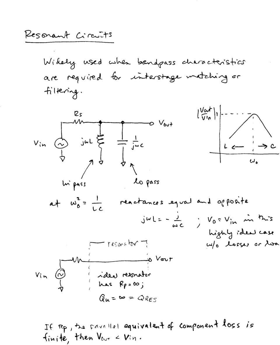
3 where we pretend that the capacitor is resonated with an ideal inductor at frequency ω. X is the capacitive reactance, and R is the series resistance. Since this Q refers only to the capacitor itself, in isolation from the rest of the circuit, it is called unloaded Q or Q U. The higher the unloaded Q, the lower the loss. Notice that the Q decreases with frequency. The unloaded Q of an inductor is given by Q U ωo = R where R is a series resistance as described above. Note that Q is proportional to frequency for an inductor. The Q of an inductor will depend upon the wire diameter, core material (air, powdered iron, ferrite) and whether or not it is in a shielded metal can. It is easy to show that for a parallel resonant circuit, the Q is given by susceptance/conductance: Q = B G where B is the susceptance of the capacitor or inductor and G is the shunt conductance. oaded Q. When a resonant circuit is connected to the outside world, its total losses (let s call them R P or G P ) are combined with the source and load resistances, R S and R. For example, C R P R S R Here is a parallel resonant circuit (C, and R P )connected to the outside. The total Q of this circuit is called the loaded Q or Q and is given by Q = ωo C ( RP RS R ) or

4 Q ωoc ωoc suscep tan ce = = = G + G + G G conduc tan ce S P total The significance of this is that Q can be used to predict the bandwidth of a resonant circuit. We can see that higher Q leads to narrower bandwidth. o BW = ω Q where ω = o 1 C 1. So, large C will increase the loaded Q at a given resonant frequency and reduce bandwidth. 2. Or, we could vary G total. How? A. Unloaded Q (Q U ) is an attribute of the passive and C components and affects G P. This will vary if we change and C. And, G P = G C + G ind, ωoc Capacitor: QU ( capacitor) = G C Inductor: 1 QU ( inductor ) = ω G o ind Using this to set the bandwidth of a resonator is not a good idea. If Q U becomes comparable to Q, then the loss in the resonator becomes very high as we shall see.
 = G C Inductor: 1 QU ( inductor ) = ω G o ind Using this to set the bandwidth of a resonator is not a good idea.")
5 Insertion oss The resonator can be used as a bandpass filter or matching network. In these applications, insertion loss can be important. G S Vout V S C Gp G Consider this resonant CR circuit. When w = wo, Vout ( jω o) G = S < 1 V G + G + G S S P Typically, G S = G = G. We need to find S 21 to determine insertion loss. Recall that S 21 2 = transducer gain = Power delivered to the load/available power from the source when the source and load are both Zo. First note that Q GP = Q G + 2G U P And, S 21 2Vout Q 2G = = 1 = V Q G + 2G S U P So, insertion loss (db): Q I = 20log 1 Q U Thus, narrow bandwidth where Q and Q U are similar can be very lossy.

6 Here is an example of a simple resonant circuit. The unloaded Q is infinite, since no losses are included in the network. We see that there is no insertion loss in this case. oaded Q varies from 1 to 10 with the given parameter sweep. Q=1 Q=10

7 Now, the circuit is modified to include a 500 ohm resistor (R P ) in parallel with the C network. This resistance represents the parallel equivalent loss due to both the and the C. So, now we have a finite unloaded Q. Note that the insertion loss increases as loaded Q, Q, approaches Q U. Sweeping RS, we see at resonance, the reactances cancel, and we are left with a resistive divider. Vout = Vin [R 1 /(2R 1 +R S )]. R S =200 R S =2000 S21 (db) = 20 log(2vout/vin)

8 So, we can set the Q and bandwidth by adjusting the loading conductances/resistances. BW ωo = Q But, we must make sure that Q U >> Q to avoid excessive losses.

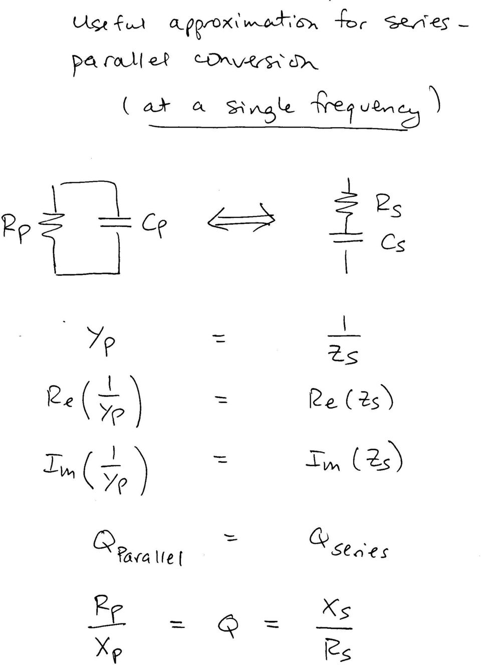
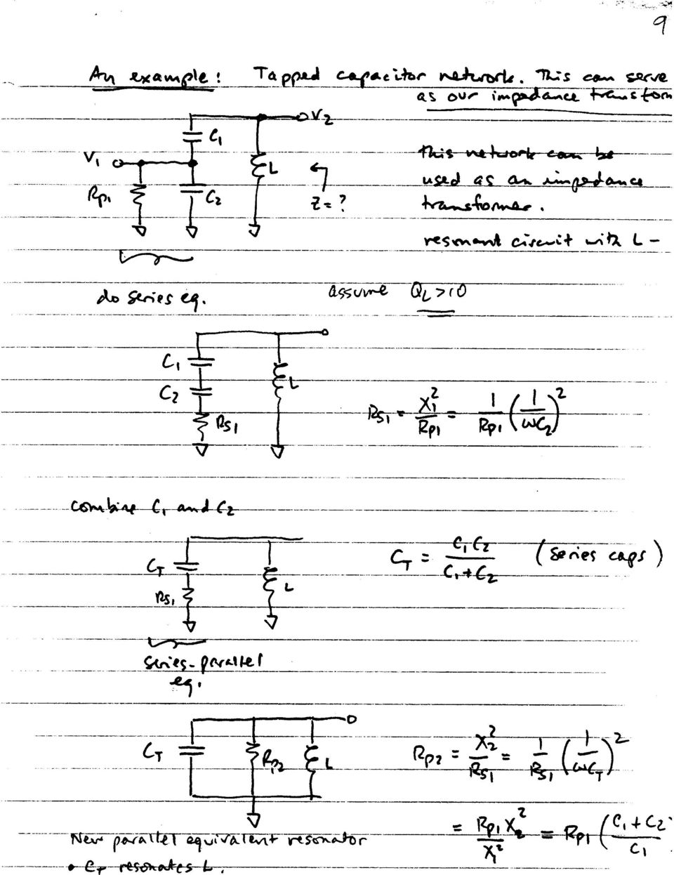
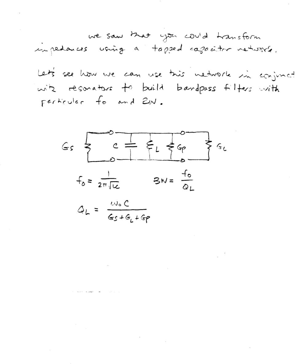
9 So, if really narrow bandwidth is required, the solution generally requires multiple resonators or more complicated bandpass filter approaches or mechanical structures like quartz crystal filters. 3. How can you set G S and G? Aren t these dictated by the generator and load? Not necessarily! We can use tapped C matching circuits to transform source and load impedances to whatever we desire (assuming we don t increase loss too much by approaching Q U ). But, first, we will introduce a convenient approximation which can be used to transform a parallel equivalent circuit into a series equivalent circuit and vice-versa.
.")
10
11

12
13

14
15 Example. Design bandpass matching network to transform 50 ohms to the input of an SA602 mixer. O The mixer input impedance is given on the data sheet as Z IN = 1.5k 3 pf for the SA602 IC. Choose a convenient frequency for this exercise: 159 MHz = 1 x 10 9 rad/sec. Use the tapped C procedure to transform 50 ohms to 1500 ohms. Include the 3 pf into the equivalent series capacitance of C1 and C2. The equivalent parallel resistance, R P, due to the unloaded Q of the components should also be taken into account in calculating the loaded Q and the transformation ratio needed to match the source and load ohms RS = 50 C ohms 3 pf Gp C 2 We need to specify a bandwidth to begin the process. et s choose 10 MHz. 159 Q = = Q U is generally limited by the inductor. The manufacturer s data generally specifies an unloaded Q at a certain frequency. For a T powdered iron core material, Q U of 120

16 is typical at this frequency. The external capacitors normally have a higher unloaded Q which can be neglected. Our first design equations: Q 1 QU = 120 ωog = P B 1/ ωo = = = 16 G G + G + G total S P Assume that G S = G = 1/1.5k = 6.7 x That is, design the tapped C network to provide a transformed impedance of 1.5k. This will get close to the solution needed. So, now we have two equations with 2 unknowns. We can solve for and for G P. G P = 2.04 x 10⁻⁴ S or R P = 4900 ohms. B = Q U G P = 2.44 x 10⁻² S 1 = 41nH ω B = o This is a rather small value and will require some care in layout to implement accurately on a PC board. Q Check insertion loss: I= 20 log 1 = 1.2 db QU If we required less loss, then a wider BW or higher Q U is necessary.

17 Next, design the tapped C network to give 1.5k R P = 1150 ohms ohms RS = 50 C 1 3pF C 2 Because is known, we can calculate the required C total to resonate at 159 MHz. C total 1 = = 24 pf ω 2 o Now, deduct the 3 pf from C total so that is is absorbed into the resonator. Design C1 and C2 for 21, not 24 pf. The transformation ratio relates C 1 and C 2. It should transform 50 ohm source into the load impedance, 1500 RP = 1150 ohms. C1+ C n = = = 4.8 C 50 1 The series combination of C 1 and C 2 CC pf C + C = = equations; 2 unknowns. Solve for C 1 and C 2. C 1 = 27 pf; C 2 = 103 pf.

18 Check the result with ADS: A small signal AC simulation is performed which includes the RP and excess C of the load. If the load is matched correctly to the source, we should see half of the source voltage at node Vin, 0.5V (available power). Vout should be 4.8 x 0.5 = 2.4V. Everything looks as expected except for the bandwidth, 11.4 MHz rather than 10 MHz. This is due to the effect of R P. If it mattered, we could go back through again and include this effect and get a 10 MHz BW, but most applications as this one are not so critical. The important thing is to get the correct impedance transformation. Of course, a network, PI or T network could also have been used here with somewhat less flexibility in choosing loaded Q.

19

20 Example of resonator used as bandpass filter: 50 ohms to 50 ohms. 100 MHz. The tapped C transforms up to 1000 ohms for this example. You can work through the design similar to the earlier example. Tapped Capacitor Resonator

21
22
23 Note the improvement in the stopband rejection provided by the coupled resonator compared with the single resonant tapped C circuit.
24 Temperature Compensation of Resonant Circuits Oscillators are frequently used to set the transmit or receive frequency in a communication system. While many applications use a phase locked loop technique to correct for frequency drift, it is good practice to build oscillators with some attempt to minimize such drift by selecting appropriate components. Inductors and capacitors often drift in value with temperature. Permeability of core materials or thermal expansion of wire causes inductance drift. Variations in dielectric constant with temperature in capacitors is the main source of drift for these components. Temperature drift is expressed as a temperature coefficient in ppm/ o C or %/temp range. Capacitors The 3 most common types of dielectrics for RF capacitors are: Dielectric type Temp coefficient (TC) Temp range C0G (or NP0) +/- 30 ppm/ o C -55 to +125C X7R (BX) (+15% to -15%) -55 to +125 Z5U (+22% to -56%) 10 to 85 Clearly, the Z5U is not much good for a tuned circuit and should be used for bypass and AC coupling (DC block) applications where the value is not extremely critical. At lower radio frequencies, polystyrene capacitors can be used. These have a 150 ppm/c TC. The C0G and X7R can be used in tuned circuits if their values are selected to compensate for the inductor drift. CK05 BX 330K 330K NP0 The two leaded capacitors above illustrate the labels found on typical capacitors of the X7R and NP0 types. The value is given by the numerals: 330. In this example, this is 33 pf. It goes 1 st significant digit (3), 2 nd significant digit (3), and multiplier (10 0 ). The letter K is the tolerance, which is +/- 10%. As always, the parasitic inductance and self resonance of any capacitor must be considered for RF applications.
25 Inductors There are many types of inductor core materials which are intended for different frequency ranges, permeability, and TC. Powdered Iron and Ferrites are the two categories of these materials. For example, the material you will have available for the VCO lab is powdered iron, Type 12 (green/white). This is useful from 50 to 200 MHz and gives Qu in the range. µ/µ 0 = 4. Manufacturer s data sheets can be found on the web that specify TCs for the many materials. This one has a weird TC vs temperature behavior, but we are mainly interested in the 25 to 50C range for this project. Temperature range TC 25 50C +50 ppm/c So, how can you compensate for component drift? NP0 X7R C 1 C 2 The equation below shows how the TCs of individual components combine 1. Suppose that the inductor was resonated with a drift free capacitor (NP0). The frequency drift will be 25 ppm/c. If the design frequency is 100 MHz, this corresponds to a drift of 2.5 khz/c. But, the equation shows that you can set the total frequency TC (TCF) of a circuit to zero by combining capacitors with different TCs. f 1 C1 C2 TCF = = TC + TCC1 + TCC2 f0 2 CTOTA CTOTA Thus, if the inductor has a positive TC, you can correct for temperature drift with the right combination of non drift and drifty capacitors. In this case, we want the total capacitance of C1 and C2 to have a net TC of 50 ppm/c. The best oscillators will be designed with components with low intrinsic TCs so that you do not have to compensate them with different components having large and possibly unreliable TCs. 1 W. Hayward, R. Campbell, and B. arkin, Experimental Methods and RF Design, ARR Press, 2003.
Impedance Matching and Matching Networks. Valentin Todorow, December, 2009
 Impedance Matching and Matching Networks Valentin Todorow, December, 2009 RF for Plasma Processing - Definition of RF What is RF? The IEEE Standard Dictionary of Electrical and Electronics Terms defines
IF Transformer. V2 is 2Vp-p sinusoidal
 V2 is 2Vp-p sinusoidal Purpose and Function These transformers are specially designed tuned circuit in RFI-tight groundable metal packages for narrow bandwith IF application. 1 Theory and Design C30 and
2.996/6.971 Biomedical Devices Design Laboratory Lecture 2: Fundamentals and PCB Layout
 2.996/6.971 Biomedical Devices Design Laboratory Lecture 2: Fundamentals and PCB Layout Instructor: Hong Ma Sept. 12, 2007 Fundamental Elements Resistor (R) Capacitor (C) Inductor (L) Voltage Source Current
Measurement of Capacitance
 Measurement of Capacitance Pre-Lab Questions Page Name: Class: Roster Number: Instructor:. A capacitor is used to store. 2. What is the SI unit for capacitance? 3. A capacitor basically consists of two
PIEZO FILTERS INTRODUCTION
 For more than two decades, ceramic filter technology has been instrumental in the proliferation of solid state electronics. A view of the future reveals that even greater expectations will be placed on
Capacitor Self-Resonance
 Capacitor Self-Resonance By: Dr. Mike Blewett University of Surrey United Kingdom Objective This Experiment will demonstrate some of the limitations of capacitors when used in Radio Frequency circuits.
BIASING OF CONSTANT CURRENT MMIC AMPLIFIERS (e.g., ERA SERIES) (AN-60-010)
 (AN-60-010)") BIASING OF CONSTANT CURRENT MMIC AMPLIFIERS (e.g., ERA SERIES) (AN-60-010) Introduction The Mini-Circuits family of microwave monolithic integrated circuit (MMIC) Darlington amplifiers offers the RF designer
BIASING OF CONSTANT CURRENT MMIC AMPLIFIERS (e.g., ERA SERIES) (AN-60-010) Introduction The Mini-Circuits family of microwave monolithic integrated circuit (MMIC) Darlington amplifiers offers the RF designer
RLC Resonant Circuits
 C esonant Circuits Andrew McHutchon April 20, 203 Capacitors and Inductors There is a lot of inconsistency when it comes to dealing with reactances of complex components. The format followed in this document
Common Emitter BJT Amplifier Design Current Mirror Design
 Common Emitter BJT Amplifier Design Current Mirror Design 1 Some Random Observations Conditions for stabilized voltage source biasing Emitter resistance, R E, is needed. Base voltage source will have finite
Critical thin-film processes such as deposition and etching take place in a vacuum
 WHITEPAPER INTRODUCING POWER SUPPLIES AND PLASMA Critical thin-film processes such as deposition and etching take place in a vacuum SYSTEMS chamber in the presence of a plasma. A plasma is an electrically
Application Note SAW-Components
 Application Note SAW-Components Principles of SAWR-stabilized oscillators and transmitters. App: Note #1 This application note describes the physical principle of SAW-stabilized oscillator. Oscillator
Frequency Response of Filters
 School of Engineering Department of Electrical and Computer Engineering 332:224 Principles of Electrical Engineering II Laboratory Experiment 2 Frequency Response of Filters 1 Introduction Objectives To
Understanding Power Impedance Supply for Optimum Decoupling
 Introduction Noise in power supplies is not only caused by the power supply itself, but also the load s interaction with the power supply (i.e. dynamic loads, switching, etc.). To lower load induced noise,
Application Note. So You Need to Measure Some Inductors?
 So You Need to Measure Some nductors? Take a look at the 1910 nductance Analyzer. Although specifically designed for production testing of inductors and coils, in addition to measuring inductance (L),
Pulsed Power Engineering Diagnostics
 Pulsed Power Engineering Diagnostics January 12-16, 2009 Craig Burkhart, PhD Power Conversion Department SLAC National Accelerator Laboratory Diagnostic Techniques and Considerations in Pulsed Power Systems
Germanium Diode AM Radio
 Germanium Diode AM Radio LAB 3 3.1 Introduction In this laboratory exercise you will build a germanium diode based AM (Medium Wave) radio. Earliest radios used simple diode detector circuits. The diodes
EDEXCEL NATIONAL CERTIFICATE/DIPLOMA UNIT 5 - ELECTRICAL AND ELECTRONIC PRINCIPLES NQF LEVEL 3 OUTCOME 4 - ALTERNATING CURRENT
 EDEXCEL NATIONAL CERTIFICATE/DIPLOMA UNIT 5 - ELECTRICAL AND ELECTRONIC PRINCIPLES NQF LEVEL 3 OUTCOME 4 - ALTERNATING CURRENT 4 Understand single-phase alternating current (ac) theory Single phase AC
Nano Stepping Notch Filter Jim Hagerman 02 01 12
 Nano Stepping Notch Filter Jim Hagerman 02 01 12 INTRODUCTION I worked out equations for the von Newman style high power notch filter. This design is tunable over a fairly wide range, but less than an
Measurement of Inductor Q with the MSA Sam Wetterlin 3/31/11. Equation 1 Determining Resonant Q from Inductor Q and Capacitor Q
 Measurement of Inductor with the MSA Sam Wetterlin 3/31/11 The of an inductor, which is its reactance divided by its internal series resistance, is used as an indication of how well it will perform at
Circuits with inductors and alternating currents. Chapter 20 #45, 46, 47, 49
 Circuits with inductors and alternating currents Chapter 20 #45, 46, 47, 49 RL circuits Ch. 20 (last section) Symbol for inductor looks like a spring. An inductor is a circuit element that has a large
S-Band Low Noise Amplifier Using the ATF-10136. Application Note G004
 S-Band Low Noise Amplifier Using the ATF-10136 Application Note G004 Introduction This application note documents the results of using the ATF-10136 in low noise amplifier applications at S band. The ATF-10136
Local Oscillator for FM broadcast band 88-108 MHz
 Local Oscillator for FM broadcast band 88-108 MHz Wang Luhao Yan Shubo Supervisor: Göran Jönsson Department of Electrical and Information Technology Lund University 2012.05.15 Abstract In this project
Application Note AN:005. FPA Printed Circuit Board Layout Guidelines. Introduction Contents. The Importance of Board Layout
 FPA Printed Circuit Board Layout Guidelines By Paul Yeaman Principal Product Line Engineer V I Chip Strategic Accounts Introduction Contents Page Introduction 1 The Importance of 1 Board Layout Low DC
Impedance Matching of Filters with the MSA Sam Wetterlin 2/11/11
 Impedance Matching of Filters with the MSA Sam Wetterlin 2/11/11 Introduction The purpose of this document is to illustrate the process for impedance matching of filters using the MSA software. For example,
Output Ripple and Noise Measurement Methods for Ericsson Power Modules
 Output Ripple and Noise Measurement Methods for Ericsson Power Modules Design Note 022 Ericsson Power Modules Ripple and Noise Abstract There is no industry-wide standard for measuring output ripple and
2. A conductor of length 2m moves at 4m/s at 30 to a uniform magnetic field of 0.1T. Which one of the following gives the e.m.f. generated?
 Extra Questions - 2 1. A straight length of wire moves through a uniform magnetic field. The e.m.f. produced across the ends of the wire will be maximum if it moves: a) along the lines of magnetic flux
Laboratory #5: RF Filter Design
 EEE 194 RF Laboratory Exercise 5 1 Laboratory #5: RF Filter Design I. OBJECTIVES A. Design a third order low-pass Chebyshev filter with a cutoff frequency of 330 MHz and 3 db ripple with equal terminations
ε: Voltage output of Signal Generator (also called the Source voltage or Applied
 Experiment #10: LR & RC Circuits Frequency Response EQUIPMENT NEEDED Science Workshop Interface Power Amplifier (2) Voltage Sensor graph paper (optional) (3) Patch Cords Decade resistor, capacitor, and
BASIC ELECTRONICS AC CIRCUIT ANALYSIS. December 2011
 AM 5-202 BASIC ELECTRONICS AC CIRCUIT ANALYSIS December 2011 DISTRIBUTION RESTRICTION: Approved for Pubic Release. Distribution is unlimited. DEPARTMENT OF THE ARMY MILITARY AUXILIARY RADIO SYSTEM FORT
AN-837 APPLICATION NOTE
 APPLICATION NOTE One Technology Way P.O. Box 916 Norwood, MA 262-916, U.S.A. Tel: 781.329.47 Fax: 781.461.3113 www.analog.com DDS-Based Clock Jitter Performance vs. DAC Reconstruction Filter Performance
LM 358 Op Amp. If you have small signals and need a more useful reading we could amplify it using the op amp, this is commonly used in sensors.
 LM 358 Op Amp S k i l l L e v e l : I n t e r m e d i a t e OVERVIEW The LM 358 is a duel single supply operational amplifier. As it is a single supply it eliminates the need for a duel power supply, thus
MEASUREMENT SET-UP FOR TRAPS
 Completed on 26th of June, 2012 MEASUREMENT SET-UP FOR TRAPS AUTHOR: IW2FND Attolini Lucio Via XXV Aprile, 52/B 26037 San Giovanni in Croce (CR) - Italy iw2fnd@gmail.com Trappole_01_EN 1 1 DESCRIPTION...3
Sophomore Physics Laboratory (PH005/105)
") CALIFORNIA INSTITUTE OF TECHNOLOGY PHYSICS MATHEMATICS AND ASTRONOMY DIVISION Sophomore Physics Laboratory (PH5/15) Analog Electronics Active Filters Copyright c Virgínio de Oliveira Sannibale, 23 (Revision
CALIFORNIA INSTITUTE OF TECHNOLOGY PHYSICS MATHEMATICS AND ASTRONOMY DIVISION Sophomore Physics Laboratory (PH5/15) Analog Electronics Active Filters Copyright c Virgínio de Oliveira Sannibale, 23 (Revision
FILTERS - IN RADIO COMMUNICATIONS
 Reading 32 Ron Bertrand VK2DQ http://www.radioelectronicschool.com FILTERS - IN RADIO COMMUNICATIONS RADIO SIGNALS In radio communications we talk a lot about radio signals. A radio signal is a very broad
LR Phono Preamps. Pete Millett ETF.13. pmillett@hotmail.com
 LR Phono Preamps Pete Millett ETF.13 pmillett@hotmail.com Agenda A bit about me Part 1: What is, and why use, RIAA? Grooves on records The RIAA standard Implementations of RIAA EQ networks and preamps
Frequency response: Resonance, Bandwidth, Q factor
 Frequency response: esonance, Bandwidth, Q factor esonance. Let s continue the exploration of the frequency response of circuits by investigating the series circuit shown on Figure. C + V - Figure The
Common-Emitter Amplifier
 Common-Emitter Amplifier A. Before We Start As the title of this lab says, this lab is about designing a Common-Emitter Amplifier, and this in this stage of the lab course is premature, in my opinion,
Impedance Matching. Using transformers Using matching networks
 Impedance Matching The plasma industry uses process power over a wide range of frequencies: from DC to several gigahertz. A variety of methods are used to couple the process power into the plasma load,
An equivalent circuit of a loop antenna.
 3.2.1. Circuit Modeling: Loop Impedance A loop antenna can be represented by a lumped circuit when its dimension is small with respect to a wavelength. In this representation, the circuit parameters (generally
Design of op amp sine wave oscillators
 Design of op amp sine wave oscillators By on Mancini Senior Application Specialist, Operational Amplifiers riteria for oscillation The canonical form of a feedback system is shown in Figure, and Equation
RFID Receiver Antenna Project for 13.56 Mhz Band
 RFID Receiver Antenna Project for 13.56 Mhz Band Fatih Eken TE 401 Microwave Course Term Project, Fall 2004 Supervised by Asst. Prof. İbrahim Tekin Telecommunication Program in Faculty of Engineering and
Printed Circuit Boards. Bypassing, Decoupling, Power, Grounding Building Printed Circuit Boards CAD Tools
 Printed Circuit Boards (PCB) Printed Circuit Boards Bypassing, Decoupling, Power, Grounding Building Printed Circuit Boards CAD Tools 1 Bypassing, Decoupling, Power, Grounding 2 Here is the circuit we
Positive Feedback and Oscillators
 Physics 3330 Experiment #6 Fall 1999 Positive Feedback and Oscillators Purpose In this experiment we will study how spontaneous oscillations may be caused by positive feedback. You will construct an active
INTEGRATED CIRCUITS DATA SHEET. TDA7000 FM radio circuit. Product specification File under Integrated Circuits, IC01
 INTEGRATED CIRCUITS DATA SHEET File under Integrated Circuits, IC01 May 1992 GENERAL DESCRIPTION The is a monolithic integrated circuit for mono FM portable radios, where a minimum on peripheral components
HP 8970B Option 020. Service Manual Supplement
 HP 8970B Option 020 Service Manual Supplement Service Manual Supplement HP 8970B Option 020 HP Part no. 08970-90115 Edition 1 May 1998 UNIX is a registered trademark of AT&T in the USA and other countries.
EMC STANDARDS STANDARDS AND STANDARD MAKING BODIES. International. International Electrotechnical Commission (IEC) http://www.iec.
 http://www.iec.") EMC STANDARDS The EMC standards that a particular electronic product must meet depend on the product application (commercial or military) and the country in which the product is to be used. These EMC regulatory
EMC STANDARDS The EMC standards that a particular electronic product must meet depend on the product application (commercial or military) and the country in which the product is to be used. These EMC regulatory
When designing. Inductors at UHF: EM Simulation Guides Vector Network Analyzer. measurement. EM SIMULATION. There are times when it is
 Inductors at UHF: EM Simulation Guides Vector Network Analyzer Measurements John B. Call Thales Communications Inc., USA When designing There are times when it is circuits for necessary to measure a operation
Power Supplies. 1.0 Power Supply Basics. www.learnabout-electronics.org. Module
 Module 1 www.learnabout-electronics.org Power Supplies 1.0 Power Supply Basics What you ll learn in Module 1 Section 1.0 Power Supply Basics. Basic functions of a power supply. Safety aspects of working
Application Note 58 Crystal Considerations for Dallas Real-Time Clocks
 www.maxim-ic.com Application Note 58 Crystal Considerations for Dallas Real-Time Clocks OVERVIEW This application note describes crystal selection and layout techniques for connecting a 32,768Hz crystal
DRAFT. University of Pennsylvania Moore School of Electrical Engineering ESE319 Electronic Circuits - Modeling and Measurement Techniques
 University of Pennsylvania Moore School of Electrical Engineering ESE319 Electronic Circuits - Modeling and Measurement Techniques 1. Introduction. Students are often frustrated in their attempts to execute
Reading: HH Sections 4.11 4.13, 4.19 4.20 (pgs. 189-212, 222 224)
") 6 OP AMPS II 6 Op Amps II In the previous lab, you explored several applications of op amps. In this exercise, you will look at some of their limitations. You will also examine the op amp integrator and
6 OP AMPS II 6 Op Amps II In the previous lab, you explored several applications of op amps. In this exercise, you will look at some of their limitations. You will also examine the op amp integrator and
Application Notes FREQUENCY LINEAR TUNING VARACTORS FREQUENCY LINEAR TUNING VARACTORS THE DEFINITION OF S (RELATIVE SENSITIVITY)
") FREQUENY LINEAR TUNING VARATORS FREQUENY LINEAR TUNING VARATORS For several decades variable capacitance diodes (varactors) have been used as tuning capacitors in high frequency circuits. Most of these
FREQUENY LINEAR TUNING VARATORS FREQUENY LINEAR TUNING VARATORS For several decades variable capacitance diodes (varactors) have been used as tuning capacitors in high frequency circuits. Most of these
LS RS. Figure 1: Assumed inductor model
 Characterizing Inductors at HF and VHF Inductors are a key component in RF circuits. Their performance makes a great difference in the operation of amplifiers, oscillators, and other circuit blocks --
Chapter 12 Driven RLC Circuits
 hapter Driven ircuits. A Sources... -. A ircuits with a Source and One ircuit Element... -3.. Purely esistive oad... -3.. Purely Inductive oad... -6..3 Purely apacitive oad... -8.3 The Series ircuit...
Application Note TDx510x
 App.Note, V 1.0, Jan 2004 Application Note TDx510x Version 1.0 Wireless Communication Never stop thinking. Edition 2004-01-28 Published by Infineon Technologies AG, St.-Martin-Strasse 53, 81669 München,
Transistor Amplifiers
 Physics 3330 Experiment #7 Fall 1999 Transistor Amplifiers Purpose The aim of this experiment is to develop a bipolar transistor amplifier with a voltage gain of minus 25. The amplifier must accept input
Introduction to the Smith Chart for the MSA Sam Wetterlin 10/12/09 Z +
 Introduction to the Smith Chart for the MSA Sam Wetterlin 10/12/09 Quick Review of Reflection Coefficient The Smith chart is a method of graphing reflection coefficients and impedance, and is often useful
Input and Output Capacitor Selection
 Application Report SLTA055 FEBRUARY 2006 Input and Output Capacitor Selection Jason Arrigo... PMP Plug-In Power ABSTRACT When designing with switching regulators, application requirements determine how
Sinusoidal. Oscillators
 364 4 Principles of Electronics Sinusoidal Oscillators 4. Sinusoidal Oscillator 4.2 Types of Sinusoidal Oscillations 4.3 Oscillatory Circuit 4.4 Undamped Oscillations from Tank Circuit 4.5 Positive Feedback
UNDERSTANDING AND CONTROLLING COMMON-MODE EMISSIONS IN HIGH-POWER ELECTRONICS
 Page 1 UNDERSTANDING AND CONTROLLING COMMON-MODE EMISSIONS IN HIGH-POWER ELECTRONICS By Henry Ott Consultants Livingston, NJ 07039 (973) 992-1793 www.hottconsultants.com hott@ieee.org Page 2 THE BASIC
AVX EMI SOLUTIONS Ron Demcko, Fellow of AVX Corporation Chris Mello, Principal Engineer, AVX Corporation Brian Ward, Business Manager, AVX Corporation
 AVX EMI SOLUTIONS Ron Demcko, Fellow of AVX Corporation Chris Mello, Principal Engineer, AVX Corporation Brian Ward, Business Manager, AVX Corporation Abstract EMC compatibility is becoming a key design
EMI and t Layout Fundamentals for Switched-Mode Circuits
 v sg (t) (t) DT s V pp = n - 1 2 V pp V g n V T s t EE core insulation primary return secondary return Supplementary notes on EMI and t Layout Fundamentals for Switched-Mode Circuits secondary primary
S-Parameters and Related Quantities Sam Wetterlin 10/20/09
 S-Parameters and Related Quantities Sam Wetterlin 10/20/09 Basic Concept of S-Parameters S-Parameters are a type of network parameter, based on the concept of scattering. The more familiar network parameters
Electronic filters design tutorial -2
 In the first part of this tutorial we explored the bandpass filters designed with lumped elements, namely inductors and capacitors. In this second part we will design filters with distributed components
SECTION 5-5: FREQUENCY TRANSFORMATIONS
 ANALOG FILTERS FREQUENCY TRANSFORMATIONS SECTION 55: FREQUENCY TRANSFORMATIONS Until now, only filters using the lowpass configuration have been examined. In this section, transforming the lowpass prototype
Chapter 19 Operational Amplifiers
 Chapter 19 Operational Amplifiers The operational amplifier, or op-amp, is a basic building block of modern electronics. Op-amps date back to the early days of vacuum tubes, but they only became common
AND8200/D. Design Considerations for ESD/EMI Filters: I (Almost Everything You Wanted to Know About EMI Filters and Were Afraid to Ask)
") Design Considerations for ESD/EMI Filters: I (Almost Everything You Wanted to Know About EMI Filters and Were Afraid to Ask) Prepared by: Ryan Hurley Applications Engineer ON Semiconductor APPLICATION
Design Considerations for ESD/EMI Filters: I (Almost Everything You Wanted to Know About EMI Filters and Were Afraid to Ask) Prepared by: Ryan Hurley Applications Engineer ON Semiconductor APPLICATION
Bipolar Transistor Amplifiers
 Physics 3330 Experiment #7 Fall 2005 Bipolar Transistor Amplifiers Purpose The aim of this experiment is to construct a bipolar transistor amplifier with a voltage gain of minus 25. The amplifier must
The Critical Length of a Transmission Line
 Page 1 of 9 The Critical Length of a Transmission Line Dr. Eric Bogatin President, Bogatin Enterprises Oct 1, 2004 Abstract A transmission line is always a transmission line. However, if it is physically
4 SENSORS. Example. A force of 1 N is exerted on a PZT5A disc of diameter 10 mm and thickness 1 mm. The resulting mechanical stress is:
 4 SENSORS The modern technical world demands the availability of sensors to measure and convert a variety of physical quantities into electrical signals. These signals can then be fed into data processing
RLC Series Resonance
 RLC Series Resonance 11EM Object: The purpose of this laboratory activity is to study resonance in a resistor-inductor-capacitor (RLC) circuit by examining the current through the circuit as a function
Measuring Insulation Resistance of Capacitors
 Application Note Measuring Insulation Resistance of Capacitors A common use of high resistance measuring instruments (often called megohmmeters or insulation resistance testers) is measuring the insulation
Ultra Low Profile Silicon Capacitors (down to 80 µm) applied to Decoupling Applications. Results on ESR/ESL.
 applied to Decoupling Applications. Results on ESR/ESL.") Ultra Low Profile Silicon Capacitors (down to 80 µm) applied to Decoupling Applications. Results on ESR/ESL. Laurent Lengignon, Laëtitia Omnès, Frédéric Voiron IPDiA, 2 rue de la girafe, 14000 Caen, France
Ultra Low Profile Silicon Capacitors (down to 80 µm) applied to Decoupling Applications. Results on ESR/ESL. Laurent Lengignon, Laëtitia Omnès, Frédéric Voiron IPDiA, 2 rue de la girafe, 14000 Caen, France
READER COMPONENTS. mifare (14443A) 13.56 MHz RFID Proximity Antennas. November 2002. Revision 1.0 PUBLIC. Philips Semiconductors
 13.56 MHz RFID Proximity Antennas. November 2002. Revision 1.0 PUBLIC. Philips Semiconductors") READER COMPONENTS mifare (14443A) 13.56 MHz RFID Proximity Antennas Revision 1.0 PUBLIC November 00 Philips Semiconductors Philips Semiconductors Rev. 1.0 November 00 CONTENTS 1 INTRODUCTION... 3 1.1 Purpose
READER COMPONENTS mifare (14443A) 13.56 MHz RFID Proximity Antennas Revision 1.0 PUBLIC November 00 Philips Semiconductors Philips Semiconductors Rev. 1.0 November 00 CONTENTS 1 INTRODUCTION... 3 1.1 Purpose
APPLICATION NOTES POWER DIVIDERS. Things to consider
 Internet Copy Rev A Overview Various RF applications require power to be distributed among various paths. The simplest way this can be done is by using a power splitter/divider. Power dividers are reciprocal
See Horenstein 4.3 and 4.4
 EE 462: Laboratory # 4 DC Power Supply Circuits Using Diodes by Drs. A.V. Radun and K.D. Donohue (2/14/07) Department of Electrical and Computer Engineering University of Kentucky Lexington, KY 40506 Updated
Mutual Inductance and Transformers F3 3. r L = ω o
 utual Inductance and Transformers F3 1 utual Inductance & Transformers If a current, i 1, flows in a coil or circuit then it produces a magnetic field. Some of the magnetic flux may link a second coil
APT0001 By: Richard Frey, P.E. High Voltage, High Efficiency MOSFET RF Amplifiers Design Procedure and Examples
 APT0001 By: Richard Frey, P.E. High Voltage, High Efficiency MOSFET RF Amplifiers Design Procedure and Examples 1 High Voltage, High Efficiency MOSFET RF Amplifiers Design Procedure and Examples Introduction
APPLICATION NOTE AP050830
 APPLICATION NOTE AP050830 Selection and use of Ultrasonic Ceramic Transducers Pro-Wave Electronics Corp. E-mail: sales@pro-wave.com.tw URL: http://www.prowave.com.tw The purpose of this application note
Chapter 4: Passive Analog Signal Processing
 hapter 4: Passive Analog Signal Processing In this chapter we introduce filters and signal transmission theory. Filters are essential components of most analog circuits and are used to remove unwanted
Physics 623 Transistor Characteristics and Single Transistor Amplifier Sept. 13, 2006
 Physics 623 Transistor Characteristics and Single Transistor Amplifier Sept. 13, 2006 1 Purpose To measure and understand the common emitter transistor characteristic curves. To use the base current gain
SECTION 13. Multipliers. Outline of Multiplier Design Process:
 SECTION 13 Multipliers VMI manufactures many high voltage multipliers, most of which are custom designed for specific requirements. The following information provides general information and basic guidance
Step Response of RC Circuits
 Step Response of RC Circuits 1. OBJECTIVES...2 2. REFERENCE...2 3. CIRCUITS...2 4. COMPONENTS AND SPECIFICATIONS...3 QUANTITY...3 DESCRIPTION...3 COMMENTS...3 5. DISCUSSION...3 5.1 SOURCE RESISTANCE...3
BSNL TTA Question Paper-Instruments and Measurement Specialization 2007
 BSNL TTA Question Paper-Instruments and Measurement Specialization 2007 (1) Instrument is a device for determining (a) the magnitude of a quantity (b) the physics of a variable (c) either of the above
Digital Systems Ribbon Cables I CMPE 650. Ribbon Cables A ribbon cable is any cable having multiple conductors bound together in a flat, wide strip.
 Ribbon Cables A ribbon cable is any cable having multiple conductors bound together in a flat, wide strip. Each dielectric configuration has different high-frequency characteristics. All configurations
Loop Bandwidth and Clock Data Recovery (CDR) in Oscilloscope Measurements. Application Note 1304-6
 in Oscilloscope Measurements. Application Note 1304-6") Loop Bandwidth and Clock Data Recovery (CDR) in Oscilloscope Measurements Application Note 1304-6 Abstract Time domain measurements are only as accurate as the trigger signal used to acquire them. Often
Loop Bandwidth and Clock Data Recovery (CDR) in Oscilloscope Measurements Application Note 1304-6 Abstract Time domain measurements are only as accurate as the trigger signal used to acquire them. Often
High Voltage Power Supplies for Analytical Instrumentation
 ABSTRACT High Voltage Power Supplies for Analytical Instrumentation by Cliff Scapellati Power supply requirements for Analytical Instrumentation are as varied as the applications themselves. Power supply
Lecture 22: Class C Power Amplifiers
 Whites, EE 322 Lecture 22 Page 1 of 13 Lecture 22: lass Power Amplifiers We discovered in Lecture 18 (Section 9.2) that the maximum efficiency of lass A amplifiers is 25% with a resistive load and 50%
Chapter 35 Alternating Current Circuits
 hapter 35 Alternating urrent ircuits ac-ircuits Phasor Diagrams Resistors, apacitors and nductors in ac-ircuits R ac-ircuits ac-ircuit power. Resonance Transformers ac ircuits Alternating currents and
Iron Powder Cores for Switchmode Power Supply Inductors. by: Jim Cox
 HOME APPLICATION NOTES Iron Powder Cores for Switchmode Power Supply Inductors by: Jim Cox Purpose: The purpose of this application note is to cover the properties of iron powder as a magnetic core material
Transistor Characteristics and Single Transistor Amplifier Sept. 8, 1997
 Physics 623 Transistor Characteristics and Single Transistor Amplifier Sept. 8, 1997 1 Purpose To measure and understand the common emitter transistor characteristic curves. To use the base current gain
EVALUATION KIT AVAILABLE Single-Chip Global Positioning System Receiver Front-End BIAS CBIAS GND GND RFIN GND GND IFSEL
 19-3469; Rev 2; 4/08 EVALUATION KIT AVAILABLE Single-Chip Global Positioning System General Description The complete single-chip global positioning system (GPS) RF front-end utilizes many innovative and
ADS Tutorial Stability and Gain Circles ECE145A/218A
 ADS Tutorial Stability and Gain Circles ECE145A/218A The examples in this tutorial can be downloaded from xanadu.ece.ucsb.edu/~long/ece145a as the file: stab_gain.zap The first step in designing the amplifier
Module 11: Conducted Emissions
 Module 11: Conducted Emissions 11.1 Overview The term conducted emissions refers to the mechanism that enables electromagnetic energy to be created in an electronic device and coupled to its AC power cord.
Application Report SLOA024B
 Application Report July 999 Revised September 2002 Mixed Signal Products SLOA024B IMPORTANT NOTICE Texas Instruments Incorporated and its subsidiaries (TI) reserve the right to make corrections, modifications,
Inductors in AC Circuits
 Inductors in AC Circuits Name Section Resistors, inductors, and capacitors all have the effect of modifying the size of the current in an AC circuit and the time at which the current reaches its maximum
LAB 12: ACTIVE FILTERS
 A. INTRODUCTION LAB 12: ACTIVE FILTERS After last week s encounter with op- amps we will use them to build active filters. B. ABOUT FILTERS An electric filter is a frequency-selecting circuit designed
Line Reactors and AC Drives
 Line Reactors and AC Drives Rockwell Automation Mequon Wisconsin Quite often, line and load reactors are installed on AC drives without a solid understanding of why or what the positive and negative consequences
MOBILE SYSTEM FOR DIAGNOSIS OF HIGH VOLTAGE CABLES (132KV/220KV) VLF-200 HVCD
 VLF-200 HVCD") MOBILE SYSTEM FOR DIAGNOSIS OF HIGH VOLTAGE CABLES (132KV/220KV) VLF-200 HVCD VERY LOW FREQUENCY (VLF) - PARTIAL DISCHARGES AND TANGENT DELTA HV/EHV POWER CABLES DIAGNOSTIC AND ON-SITE FIELD TESTING WITH
MOBILE SYSTEM FOR DIAGNOSIS OF HIGH VOLTAGE CABLES (132KV/220KV) VLF-200 HVCD VERY LOW FREQUENCY (VLF) - PARTIAL DISCHARGES AND TANGENT DELTA HV/EHV POWER CABLES DIAGNOSTIC AND ON-SITE FIELD TESTING WITH
An Overview of Practical Capacitance Bridge Functioning. by Paul Moses
 An Overview of Practical Capacitance Bridge Functioning by Paul Moses INTRODUCTION The laboratory has a variety of bridges, both automatic and manual which can be used to measure the capacitance and dielectric