Chapter 1: Introduction to Spacecraft Propulsion Peter Erichsen, September 2006
|
|
|
- Sybil Gregory
- 9 years ago
- Views:
Transcription
1 - 1- Chapter 1: Introduction to Spacecraft Propulsion Peter Erichsen, September 2006 S.1 Spacecraft Propulsion Systems Spacecraft propulsion is based on jet propulsion as used by rocket motors. The principle of rocket propulsion was known as far back as 360B.C. In the 13 th century solid rocketpowered arrows were used by the Chinese military. The Second World War and the cold war advanced rocket missile development in modern time. Later, space opened up to exploration and commercial exploitation by satellites and robot spacecraft. This lecture will introduce the basic aspects of rocket propulsion, with focus on analysis and performance of spacecraft propulsion systems. Key features and performance characteristics of existing and planned (near future) propulsion systems for use on spacecraft are summarized.

2 - 2- S.2 Educational Objectives In this chapter you will learn about: Different applications of propulsion Typical space propulsion tasks The main characteristics of spacecraft propulsion What kind of propulsion systems exist

3 - 3- S.3 Need of Propulsion Propulsion is needed to: Place payloads into orbit: launch propulsion is used; Send payloads to the moon or to the planets: space propulsion is used; Position, adjust and maintain orbits of spacecrafts by orbit control: auxiliary propulsion is used; Orient spacecraft by attitude control: auxiliary propulsion also called reaction-control systems is used.

4 - 4- Payloads The Payload is the revenue-producing portion of a spacecraft load, e.g., passengers and cargo such as scientific experiments, TV transmitters, earth observation equipment like photo cameras, etc. Spacecrafts Spacecraft is the collective name of devices, which are designed to be placed into space, comprising earth satellites, interplanetary and trans-solar types of space probes. Spacecraft can be manned or unmanned.

5 - 5- Orbit control ORBIT CONTROL comprises: Orbit changes: - Moving a spacecraft to a desired orbit, including plane changes, orbit injection, deorbit, etc.

6 Orbit Maintenance or Station Keeping : Keeping a spacecraft in the desired mission orbit, i.e. compensating for effects of disturbing forces like drag, solar wind, gravitational forces, etc. Attitude control Changing the attitude, that is changing the orientation of a spacecraft to the desired direction. Keeping a spacecraft to the desired direction by compensating for disturbing torques.

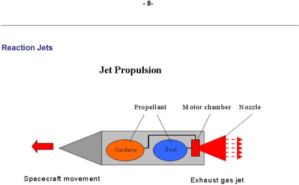
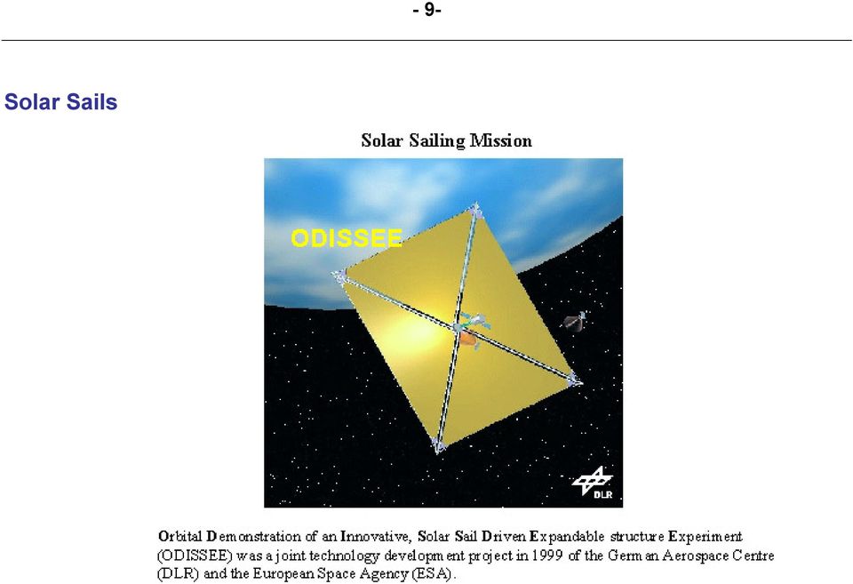
7 - 7- S.4 Reaction-Control System There are the following types of reaction control systems: Reaction Jets (propulsion): which produce a control force by the expenditure of mass; Solar Sails, Magnetic Torquers (magnetic coils): which produce a control force by interaction with the environmental field; Momentum-Transfer Devices (reaction-, flywheels): which produce no net control force, but simply transfer angular momentum to or from the spacecraft. Odin Satellite Swedish small satellite project for astronomical and atmospheric research. Launched in February 2001 on a Start-1 launch vehicle from Svobodny.
: which produce no net control force, but simply transfer angular momentum to or from the spacecraft.")
8 Reaction Jets - 8-
9 Solar Sails - 9-
10 - 10- Momentum Transfer Devices of TUB-Sat Part of micro-satellite DLR-TUBSAT with reaction Wheels (Technical University of Berlin). Reaction wheels are used for three axis stabilization and orientation of the satellite. Each reaction wheel is connected with a laser gyro in the same axis. The complete control loop electronics is integrated in the reaction wheels. Each axis gets the angle or angle velocity command from the On Board Data Handling System (Central Processor) but all other activities are controlled by the reaction wheel itself.

11 - 11- S.5 Jet Propulsion System These systems are based on jet propulsion devices that produce thrust by ejecting stored matter, called the propellant. The main features of jet propulsion are: Launch Propulsion for launching rockets with the following characteristics: - high velocity increment capability ( km/s) - very high thrust levels (ratio thrust/launch vehicle weight: >1.3 ) - low fraction of take-off mass of launch vehicle for payload mass (1-5%) of the launching vehicle - powerful chemical rockets Rocket launch

12 - 12- Velocity increment Required Velocity Change Velocity increment v (m/s) of launch/space maneuvers. (Change in velocity imparted to the launcher/spacecraft by the propulsion system to complete space maneuvers; data listed are indicative only) START DESTINATION TYPICAL V REQUIREMENT m/s Kourou (French Guiana) LEO GTO REMARKS Equatorial ( v-gain by earth rotation: 465 m/s) Cap Canaveral LEO Equatorial (USA) GEO LEO GEO Change of inclination: 28, Cap Canaveral GTO GEO LEO (parking) GEO GEO Earth orbit escape Lunar orbit Mars orbit North/South station-keeping: 50 /year East/West station-keeping: 3 6 /year Attitude control: 3% of total propellant budget Change of inclination: 9, Kourou Change of inclination: 28, Cap Canaveral On orbit operations (orbit maintenance requirements per year) Into planetary trajectory Legend: LEO = Low Earth Orbit ( 300 km) GTO = Geostationary Transfer Orbit (Apogee: km; Perigee: 200 km) GEO = Geostationary Earth Orbit ( km)
 GEO GEO Earth orbit escape Lunar orbit Mars orbit 1 500 1 800 North/South station-keeping: 50 /year East/West station-keeping: 3 6 /year Attitude control: 3% of total propellant")
13 - 13- S.6 Spacecraft Propulsion Spacecraft Propulsion is characterized in general by its complete integration within the spacecraft (e.g. satellites). Its function is to provide forces and torques in (empty) space to: - transfer the spacecraft: used for interplanetary travel - position the spacecraft: used for orbit control - orient the spacecraft: used for attitude control SMART-1 Spacecraft Mission to Moon to demonstrate innovative and key technologies for scientific deep-space missions. Nov Sept While jet propulsion systems for launching rockets are also called primary propulsion systems, spacecraft, e.g. satellites, are operated by secondary propulsion systems.

14 - 14- S.7 Characteristics of Spacecraft Propulsion Systems In order to fulfill attitude and orbit operational requirements of spacecraft, spacecraft propulsion systems are characterized in particular by: Very high velocity increment capability (many km/s) Low thrust levels (1 mn to 500 N) with low acceleration levels Continuous operation mode for orbit control Pulsed operation mode for attitude control Predictable, accurate and repeatable performance (impulse bits) Reliable, leak-free long time operation (storable propellants) Minimum and predictable thrust exhaust impingement effects

15 - 15- Impulse bits Impulse bit is the smallest change in momentum required to allow for e.g. fine attitude and orbit control of a spacecraft. Storable propellants Storable Propellants are liquid (or gaseous) at ambient temperature and can be stored for long periods in sealed tanks, e.g. monopropellant hydrazine (see chapter S1B8C3). In contrast, cryogenic propellants, which are liquefied gases at low temperature, such as liquid oxygen (-147 C) or liquid hydrogen (-253 C) are difficult to be used for long space flight missions. Note: at present only storable propellants are used for space flight missions.

16 - 16- S.8 Classification of Propulsion Systems Spacecraft propulsion can be classified according to the source of energy utilized for the ejection of propellant: Chemical propulsion use heat energy produced by a chemical reaction to generate gases at high temperature and pressure in a combustion chamber. These hot gases are accelerated through a nozzle and ejected from the system at a high exit velocity to produce thrust force. Electric propulsion uses electric or electromagnetic energy to eject matter at high velocity to produce thrust force. Nuclear propulsion uses energy from a nuclear reactor to heat gases which are then accelerated through a nozzle and ejected from the system at a high exit velocity to produce thrust force.

17 - 17- Nuclear propulsion SCHEMATIC OF A THERMO-NUCLEAR ROCKET ENGINE Propellant Tank Turbin Nuclear Reactor Reactor Fuel Element Nozzle Coolant Jacket Note Exhaust Gas While chemical and electric systems are used for the propulsion of today s spacecrafts, nuclear propulsion is still under study. Therefore, only chemical and electric propulsion will be dealt within this book.

18 - 18- S.9 Summary Propulsion is needed for launching of spacecrafts, for spacecraft orbit transfer as well as their orbit and attitude control. Here, only propulsion systems will be dealt with which are based on jet propulsion devices that produce thrust by ejecting stored matter, called the propellant. Differences of launch and space propulsion have been mentioned. Propulsion subsystem requirements have been listed. Jet propulsion can be classified according to the source of energy utilized for the ejection of propellant: chemical, electric and nuclear.

19 - 1- Chapter 2: Basic Propulsion Equations Peter Erichsen, September 2006 S.1 Basic Propulsion Relations This chapter is devoted to the basic laws governing propulsion systems. The chapter will give an overview of the set of equations used in the field of spacecraft propulsion. Understanding these laws is necessary in order to be able to select an appropriate propulsion system and to design its components. The basic laws include the Rocket Equation, the rocket thrust force and other propulsion performance parameters. In addition two types of propulsion are presented together with the appropriate set of equations characterizing the systems in question.

20 - 2- S.2 Educational Objectives This chapter will cover the following topics: Basic Rocket Equation Determination and measure of rocket thrust force Determination of the mass of propulsion systems Key parameters which determine propulsion performance, Principles of chemical and electric propulsion systems, Chemical and electric propulsion system constraints

21 - 3- S.3 Basic Equation of Thrust Basic rocket propulsion equations are based on Newton Law of Motion For constant propellant exhaust velocity v e at thruster nozzle outlet, and with thrust force F collinear to v e, gives the The Basic Equation for Force of Thrust F o = [N] mv e From the Law of Conservation of Momentum follows: v m = m [Ns] v e which is the change of momentum of spacecraft. This implies the change of momentum of the expelled propellant.
22 - 4- Newton Law of Motion Isaac Newton ( ) F d( m v) d v dm = = m + v, [N] dt dt dt For F=0 For F 0 For F 1 =-F 2 1. Every object in a state of rest or uniform motion tends to remain in that state of rest or motion unless an external force is applied to it. 2. Force is equal to the change in momentum (mv) per change in time 3. Whenever one object exerts a force on a second object, the second object exerts an equal and opposite force on the first The Basic Equation for Force and Thrust dm o F = ve = mv e [N], with dt dm o = [kg/s] for propellant mass flow rate dt m F = Thrust force [N] o m = Propellant mass flow rate [kg/s] v e = Propellant exhaust velocity at nozzle outlet ( thruster exhaust velocity) [m/s]
23 - 5- S.4 Basic Rocket Equation Total Velocity Increment v of a spacecraft: v= v v= 0 dv = v m e m f S / C dm m after integration: m f v = ve ln [m/s] ms / C This formula can be also written in a form called Basic Rocket Equation Basic Rocket Equation m m f S / C = e v v e Tsiolkovsky Equation Tsiolkovsky ( )
24 - 6- S.5 Total Impulse From the Basic Rocket Equation follows with m f = m S/C m P : Propellant Quantity required for a spacecraft velocity change v: m P ms C 1 e v = v e / [kg] The Total Impulse delivered by a certain quantity of propellant is calculated by: I tot τ m p = Fdt = ve 0 0 dm = v e m p [Ns] This equation shows again the importance of the thruster exhaust velocity. For a given mass of propellant, m P, the thruster exhaust velocity v e shall be high for obtaining a high (delivered) total impulse, I tot.
25 - 7- S.6 Propulsion Performance Factors Propulsion Performance is determined by Specific Impulses which permits an objective and comparative evaluation of thrust engines and propulsion systems of different designs and with different propellants: Thruster Performance Factor The most useful parameter for determining thrust engine (or thruster) performance is Thruster-specific Impulse: F I sp = [Ns/kg] o m The I sp is defined as the impulse delivered per unit mass of propellant and which can be easily obtained by Test.
26 - 8- Thruster-specific Impulse F I sp = [Ns/kg] o m I sp = thruster specific impulse [Ns] F = thrust force [N] o m = Propellant mass flow rate [kg/s] Specific impulses are often quoted in units of seconds, corresponding to a modification of the above definition to that of the impulse delivered per unit of weight of propellant. The values in seconds then follow from those in Ns/kg by division with the gravitational acceleration standard, g (=9.82 m/s 2 ). with: F I sp = = o mg o 0 o m g = w F o w [s] 0 [kp/s] in propellant weight flow unit
27 Test - 9-
28 - 10- S.7 Effective Exhaust Velocity F v e = [m/s] o m v e = effective exhaust velocity [m/s] F = thrust force [N] o m = propellant mass flow rate [kg/s] From its definition as the thrust per unit rate of mass flow of propellant, it follows that v e is numerically the same as the I sp as defined above with SI units of m/s. Note: v e is the effective exhaust velocity, - although called thruster exhaust velocity hereinafter-, because it is determined by test; therefore, in all propulsion related calculations with v e, the effective exhaust velocity has to be applied, if not stated otherwise.
29 - 11- S.8 Propulsion System Performance Propulsion System Performance Factor: System-specific Impulse, I ssp Another very important quantity is the System-specific Impulse, I ssp, which is the total impulse, I tot delivered by the system, divided by the total mass, m PS, of the propulsion system, that is, all of the propulsion system and not only the propellant as for I sp : I tot I ssp = [Ns/kg] mps I ssp = system-specific impulse [Ns/kg] I tot = total impulse delivered by the propulsion system [Ns] m PS = mass of propulsion system [kg] I ssp is a very useful tool, but its practical application requires a very clear definition of what is included in total mass of propulsion system. Details of how the I ssp is determined for each kind of propulsion system are dealt with in the I ssp Program in chapter 4.
30 - 12- The mass of propulsion systems can be determined with help of the overall Propulsion System Mass Fraction m m PS S / C : v = v I e tot vems C 1 e [Ns] / I tot I ssp = I tot = I sspmps [Ns/kg] m m m PS S / C PS 1 e 1 e v v v I sp = e ve v e I ssp = I ssp Propulsion System Mass Fraction m PS = mass of propulsion system (including propellant) [kg] m S/C = total mass of spacecraft (vehicle) [kg] I sp = thruster specific impulse [Ns/kg] v e = thruster exhaust velocity [m/s] I ssp = system specific impulse [Ns/kg] = thruster exhaust velocity [m/s] v e The first equation above is obtained from the rocket equation. The second equation is just the definition of I ssp, and the final expression follows from the first two.
31 - 13- S.9 Type of Propulsion Systems The basic propulsion mathematical formulas presented have to be further expanded for today's commonly used on-board spacecraft propulsion system types: Chemical Propulsion Systems The energy to produce thrust is stored in the propellant, which is released by chemical reactions and the propellant is then accelerated to a high velocity by expanding it in form of gas through a nozzle. Electric Propulsion Systems The energy to produce thrust is not stored in the propellant but has to be supplied from outside by an extra power source, e.g. nuclear, solar radiation receivers or batteries. Thrust is produced by: - expansion of hot gas (which is heated by electric current) - accelerating of charged particles in electric or magnetic fields to high expulsion velocities.
32 - 14- S.10 Chemical Propulsion Chemical Propulsion is based on the principle of converting chemical energy into kinetic energy of the exhaust gases in a nozzle of a rocket propulsion device. Typically, rockets using solid propellants are called motors and rockets using liquids are called engines. The term thruster is used for small thrust applications, e.g. in spacecraft auxiliary propulsion systems. Rocket propulsion device basic parts
33 - 15- Rocket propulsion device basic parts A rocket propulsion device has 3 basic parts: Thrust (combustion) Chamber, where the propellant burns, producing hot gas Converging section (throat), to constrict the flow of hot gases, thus controlling chamber pressure and mass flow rate Nozzle, to accelerate the gas flow to high velocity in the desired direction The schematic of a rocket engine is presented below, showing the main rocket thrust chamber performance parameters.
34 - 16- Maximum Exhaust Velocity Conservation of energy applied for gas flow in nozzles: decrease of enthalpy H (H=c p T) is equal to the increase of kinetic energy (½ Mv 2 ) applied to one mole of perfect gas the velocity of the gas when leaving the nozzle exit (index E) is given v E = 2 M ( H H ) o E [m/s] and the theoretical maximum value for v E is for H E =0, that is all enthalpy has been used to increase the kinetic energy of the expelled gas molecules: v E max = 2 M ( H ) o = 2κ κ 1 RT M [m/s] where κ is the ratio of specific heat, R is the universal gas constant, T is the absolute temperature and M is the molecular mass. Note that the exhaust velocity is a function of mainly temperature T and molar mass M T v E [m/s] M
35 - 17- The Effective Exhaust Velocity (measured) is: v P A E E e = ve + = C C o F = m F o m [m/s] Typical values of v v e E max : for cold gas for hot gas v e < v Emax is due to: Thermal losses in the motor Friction losses in nozzle (boundary losses due to separation of gas flow from nozzle wall) Nozzle exit pressure P E > P governed by nozzle expansion ratio (< 200) Losses due to gas condensation and gas dissociation in nozzle
36 - 18- S.11 Electrical Propulsion An Electric Propulsion system is a mass expulsion system in which electric energy is used to create or augment the kinetic energy in the expelled mass. Consequently electric power will be of main interest in the performance evaluation of such systems. Kinetic Energy of Ejected Matter 1 2 E jet = m pve [Ws] 2 Power of the Jet de o jet P jet = = mve = dt 2 v F e [W] Power Input 2 P o jet ve ve P = = m = F η 2η 2η [W] where η is the power conversion efficiency.
37 - 19- Kinetic energy in the expelled mass Electric propulsion leads to higher exhaust velocities achieved by chemical propulsion (v e < 5000 m/s), by this saving mass of propellant. Power Input Since power is the major constrain for electric thrusters on spacecraft, the following example will illustrate the impact of power on limiting of thrust levels for electric propulsion. The power input to a thruster system is: v e 2η P = F [W] F = P [N] 2η v e With the assumption: P = 1000W power input η = 1 (to simplify) = m/s typically for electric thrusters v e The resulting thrust will be: 2 W Nm / s F = 1000 = m / s [ N ] Conclusion: Thrust levels of electric propulsion will be << thrust levels of chemical propulsion
38 - 20- S.12 Summary Fundamentals of rocket propulsion: - Thrust force is generated by expelling mass (initially stored in the spacecraft) from the spacecraft at high velocity; - Basic Rocket Equation trades off exhaust velocity v e with spacecraft mass fraction R; Propulsion performance is determined by Specific Impulses : - Thruster-specific impulse, I sp (Ns/kg), which is numerically the same (If defined with SI units of m/s) as the effective exhaust velocity v e (m/s), - although called thruster exhaust velocity hereinafter. The exhaust velocity increases with increasing gas temperature and decreasing molar mass. - Propulsion System-specific Impulse, I ssp (Ns/kg), which is the total impulse, I tot (Ns) delivered by the system, divided by the system total mass, m PS (kg). Mass of propulsion systems can be determined with help of the overall Propulsion System Mass Fraction, m PS /m S/C. Power is the major constraint for electric thrusters on spacecraft. Therefore thrust levels of electric propulsion will be << thrust levels of chemical propulsion.
39 - 1- Chapter 3: Spacecraft Propulsion Systems Survey Peter Erichsen, September 2006 S.1 Survey of Spacecraft Propulsion Systems In the progressing Space Age, spacecrafts such as satellites and space probes are the key to space exploration, space science and space commerce. Of particular interest is spacecraft propulsion, which is necessary to maneuver or steer spacecrafts in the absence of aerodynamic forces. An overview of common basic spacecraft propulsion system designs is presented together with supporting tables and graphs. Key features and performance characteristics of existing and planned (near future) propulsion systems for use on spacecraft are summarized. This will help to understand their potential application based on basic system performance characteristics like thrust levels, thruster and system specific impulse, etc.
40 - 2- S.2 Educational Objectives In this chapter you will learn: Classification of propulsion systems based on type of energy source Basic configuration of propulsion systems Main performance characteristics of propulsion systems Advantages and disadvantages of propulsion systems
41 - 3- S.3 Propulsion System Options Spacecraft Propulsion System Options: Spacecraft Propulsion Systems can be classified according to the type energy source. Both space propulsion and auxiliary propulsion are performed by the following two main on-board spacecraft propulsion system types: Chemical Propulsion Systems: The energy to produce thrust is stored in the propellant, which is released by chemical reactions and the propellant is then accelerated to a high velocity by expanding it in form of gas through a nozzle. Currently available chemical propulsion systems can be categorized as either: hot gas or cold gas system. Electric Propulsion Systems: The energy to produce thrust is not stored in the propellant but has to be supplied from outside by an extra power source, e.g. nuclear, solar radiation receivers or batteries. Thrust is produced by: - Expansion of hot gas (which is heated by electric current) in a nozzle, - Accelerating of charged particles in electric or magnetic fields to high expulsion velocities.
42 - 4- Classified According to the Type Energy Source
43 - 5- Chemical Propulsion Systems Chemical Propulsion systems comprise the following main components Storage and feed system that stores and feeds the propellant to the thrusters to generate thrust Valves, piping which connects the propellant storage system with the thruster Electric control unit to operate electrically the valves and thrusters
44 - 6- Electric Propulsion Systems Electric propulsion systems comprise the following main components: Storage and feed system that stores and feeds the propellant to the thrusters to generate thrust Valves, piping which connects the propellant storage system with the thruster Electric control unit to operate electrically the valves and thrusters Electric power supply and power processing system
45 - 7- S.4 Cold and Hot Gas Systems Cold Gas Systems operate with propellants like compressed inert gas (e.g. nitrogen: N 2 ) or high vapor pressure hydrocarbons (e.g. propane: C 3 H 8 ). - Main performance - Advantages - Disadvantages - Conclusion Hot Gas Systems are the most common type of propulsion systems for space applications. They can be divided into three basic categories defined by the physical state of the stored propellants in the propulsion system. In contrast to compressed gas and vaporizing liquids, liquid propellants in hot gas systems need to be pressurized in the tank to feed the thrusters with propellant. These systems are called pressure-fed systems. Note
46 Cold Gas Systems - 8-
47 - 9- Cold Gas Systems (Operate) Cold gas propulsion is just controlled pressurized gas source and a nozzle. It represents the simplest form of a propulsion system. The typical system operating with cold gas consists of a propellant tank, fill valve, filter, pressure regulator, line pressure transducers and thrusters. The pressure regulator provides propellant at constant pressure as the tank pressure drops. A relief valve is incorporated downstream of the pressure regulator to prevent system rupture in the case of a regulator failure. With regard to compressed gas systems, the cold gas is stored at high pressures in a tank. The vaporizing liquid system is characterized by a liquid propellant pressurized by its own equilibrium vapor pressure and the expulsion of its vapor through a nozzle. In order to provide completely vaporized gas, a vaporized is included in liquid cold gas systems. Nitrogen, argon, krypton, Freon 14, ammonia and propane have been employed in operational spacecraft, but nitrogen has been the most common cold-gas propellant.
48 - 10- Propellants CHARACTERISTICS OF SOME CANDIDATE COLD GAS PROPELLANTS
49 Typical System - 11-
50 Thrusters - 12-
51 - 13-
52 - 14- Main performance of Cold Gas Systems - Thrust level: N - Impulse bit: 10-5 Ns (with thruster minimum on-time of 5 ms) Note from the propellant table: - Thruster-spec. Impulse: Ns/kg [ v e (m/s)] - System-spec. Impulse: Ns/kg Although hydrogen gas provides the highest Thruster-spec. Impulse, it offers the lowest System spec. Impulse because of the low gas density with resulting high mass of propellant storage system (tank + gas). In contrary, systems operating with vapor pressure hydrocarbons (e.g. propane: C 3 H 8 ) have higher System-spec. Impulses because of the high gas density (stored as a liquid). However, because of simplicity, nitrogen has been the most common cold-gas propellant.
53 - 15- Advantages Simplicity and reliability Lowest cost propulsion system Very low thrust ( N) and impulse bit ( 10-5 N) capability Low contamination of exhaust gases (plume) on spacecraft outer surface Disadvantages Low I sp ( 950 Ns/kg) low I ssp ( 700 Ns/kg) with resulting high system mass Conclusion Although of moderate impulse capability, cold gas systems, in particular systems operating with compressed cold gas, are still of interest in view of their simplicity, high reliability and repeatability of impulse bit. Therefore, cold gas has many applications where simplicity is more important than high performance. For increasing absolute levels of thrust and impulse requirements for spacecraft propulsion (e.g. attitude and orbit control), cold gas systems are inadequate and more energetic propellants generating hot gas for mass expulsion are required.
54 - 16- S.5 Categories of Hot Gas Systems REMEMBER! In order to obtain higher I ssp, in the first instance higher v e is needed. This can be achieved by increasing the temperature of the exhaust gases to be expanded in the thruster nozzle. Hot Gas Systems Hot gas systems are the most common type of propulsion system used for space applications.
55 - 17- Liquid Propellants Characteristics of Liquid (storable) Propellants for Spacecraft Applications
56 - 18- Pressure-Fed Systems Note Note that due to long space flight mission duration, only pressure-fed systems are used because of their inherent simplicity compared with pump-fed systems, which are used commonly for launch propulsion. In addition, for long space flight missions, only storable propellants, which can be stored for long periods in sealed tanks, are used.
57 - 19- S.6 Liquid Propellant Systems Monopropellant systems operate with a single (Mono) propellant to produce thrust. The most commonly used monopropellant is anhydrous hydrazine (N 2 H 4 ). - Main performance - Advantages - Disadvantages Bipropellant systems operate by the combustion of two (Bi) propellants, a fuel (e.g. MMH) and an oxidizer (e.g. N 2 O 4 ), to produce thrust. Bipropellant systems are used e.g. for telecommunication satellites which operate in Geostationary Orbits. Here, propulsion systems are needed for spacecraft injection from the orbit delivered by the launcher into circular orbit, and during station phase for orbit (north/south & east/west) and attitude control. Therefore, these propulsion systems are also called Unified Propulsion Systems (UPS).
58 Monopropellant Systems - 20-
59 - 21- Monopropellant Systems (Operate) The hydrazine propellant is decomposed in a thruster by a catalyst and the resulting hot gas is expelled through a nozzle, thus generating thrust force on the spacecraft. A typical monopropellant system uses nitrogen or helium gas to expel the propellant from a diaphragm tank into the chamber catalyst beds of the thrusters. Since the pressuring gas is stored (at a pre-selected but relatively low pressure, e.g. 22 bar) in the propellant tank, the propellant pressure varies with propellant usage. A typical selection of the ullage volume of 25% filled with pressuring gas (thus containing 75% propellant) will results in a propellant feed pressure decay, and thus in a thrust decay of 4:1. This mode of operation is also referred to as the blow-down mode, in contrast to the pressure constant mode, which requires the storage of a high-pressure gas in a tank external to the propellant tank (see bipropellant systems). In a hydrazine gas generator system, the hydrazine decomposition gases are exhausted into a gas storage tank for later gas expulsion. The catalytic thruster and gas generator systems have identical propellant feed systems consisting typically of propellant tank(s) with a diaphragm expulsion device(s), propellant and gas fill valves, eventually latch valves (start valves), line pressure transducers and filters.
60 Thruster - 22-
61 - 23-
62 - 24-
63 - 25-
64 Typical Monopropellant System - 26-
65 Diaphragm Tank - 27-
66 - 28- Main Performance of Monopropellant Systems Thrust level: N for satellites, up to 450 N for e.g. Ariane third stage auxiliary propulsion Impulse bit: 10-2 Ns (with thruster minimum on-time of 20 ms) Thruster-spec. Impulse: 2300 Ns/kg [ v e (m/s)] for continuous mode operation Thruster-spec. Impulse: Ns/kg for pulse mode operation System-spec. Impulse: 1860 Ns/kg
67 - 29- Advantages Simplicity and reliability (monopropellant) Lowest cost propulsion system (other than cold gas) Space storable for long periods (> 12 years demonstrated) Low thrust capability Moderate thrust levels available ( 400 N) Disadvantages Moderate I sp ( 2300 Ns/kg) with moderate I ssp (< 1900 Ns/kg) resulting in medium/high system mass Limited life of catalyst Satellite outer surface contamination (NH 3 ) moderate
68 - 30- Bipropellant/Dual-Mode Systems Bipropellant Systems
69 - 31- Bipropellant Systems (Operate) Bipropellant systems are characterized by the combustion of two (Bi) propellants, a fuel (e.g. MMH) and an oxidizer (e.g. N 2 O 4 ) to produce thrust. The propellants are injected separately into the bipropellant thruster combustion chamber where they react spontaneously (hypergolic propellant) to perform high-temperature, low molecular weight combustion products, which are the expelled through a nozzle. The system basically consists of a pressurizing-gas system, propellant tanks (with surface tension propellant management devices), propellant lines and thrusters. Unlike hydrazine thrusters, bipropellant thrusters accept only a limited range of propellant inlet pressure variation of 2. Therefore, the high-pressure gas, generally nitrogen or helium is regulated to the desired tank pressure, e.g. 17 bar. This mode of operation is also referred to as the pressure constant mode. The system contains check valves upstream of the propellant tanks to prevent possible back-flow, mixing, and combustion of the propellant vapors in the common pressuring gas line. Relieve valves are incorporated in the system upstream of the propellant tanks to prevent system rupture in the event of a pressure regulator failure. Filters are provided in the propellant lines directly upstream of the thruster valves to prevent clogging of the injector or damage of the valve seat by entrained foreign material. Finally, the system contains pyro- or latch valves, line pressure transducers, fill and drain valves and various test ports for system check out.
70 Bipropellant thruster - 32-
71 - 33-
72 - 34-
73 - 35-
74 - 36-
75 Propellant Tanks - 37-
76 - 38-
77 Unified Propulsion Systems - 39-
78 - 40-
79 - 41-
80 - 42-
81 - 43- Main Performance of Bipropellant Systems Thrust level: 4 500N for satellites, up to N for general spacecraft application Impulse bit: 10-2 Ns (with thruster minimum on-time of 20 ms) Thruster-spec. Impulse: 2850 Ns/kg for F 25N (for steady state operation) 3110 Ns/kg for F 400N Thruster-spec. Impulse: 1000 Ns/kg (for pulse mode operation) System-spec. Impulse: 2800 Ns/kg Advantages Higher Thruster-spec. Impulse, I sp ( 3110 Ns/kg) Higher System-spec. Impulse I ssp ( 2800 Ns/kg) resulting in low system mass High thrust capability, up to N Disadvantages Bipropellant system complexity with added valves, regulators, etc. Higher cost in comparison to monopropellant hydrazine systems.
82 Dual-Mode Systems - 44-
83 - 45- Dual-Mode systems use hydrazine (N 2 H 4 ) both as fuel for a bipropellant (N 2 H 4 /N 2 O 4 ) Liquid Apogee Engine (LAE) and as monopropellant for on-orbit Attitude and Orbit Control Systems (AOCS) from a common fuel tank. The propulsion system layout is shown in the popup with the propellant feed system design similar to that of the bipropellant system, as described earlier. Advantages Higher Thruster-spec. Impulse, I sp ( 3110 Ns/kg) for orbit maneuvers Common fuel tank for attitude/orbit control and orbit Can use higher performance station keeping thruster, e.g. Power Augmented Catalytic Thruster (PACT) at I sp = 3000 Ns/kg versus I sp = 2900 Ns/kg for F = N (bipropellant thrusters) if required. Disadvantages Dual-Mode system complexity with added valves, regulators, etc. Higher cost in comparison to monopropellant hydrazine systems.
84 - 46- Future Developments in Liquid Propellant Technology Need: Environmentally friendly, safer propellants. Current spacecraft and satellite users and manufacturers are looking for more environmentally friendly, safe propellants. These can reduce cost by eliminating the need for self-contained atmospheric protective ensemble (SCAPE) suits that are needed for toxic propellants. Moreover, extensive and prohibitive propellant safety precautions, and isolation of the space vehicle from parallel activities during propellant loading operations can be minimized or eliminated. If used on these satellites, the costs for operating the vehicles will be lowered, in some cases dramatically.
85 - 47- Under Development: A new family of environmentally friendly monopropellants has been identified as an alternative to hydrazine. These new propellants are based on blends of e.g. hydroxyl ammonium nitrate (HAN), ammonium dinitramide (AND), hydrazinium nitroformate (HNF), nitrous oxide (N 2 O), and hydrogen peroxide (H 2 O 2 ) When compared to hydrazine, e.g. HAN blends have a range of specific impulse (I sp ) which can exceed that of hydrazine. Testing of HAN based propellants has begun to show promise and could soon be adopted for on-board propulsion systems of LEO satellites and constellations. Advantages: Safer propellants (also called green or reduced hazard propellants ) reduce costs by: Eliminating the need for self-contained atmospheric protective ensemble (SCAPE) suits needed for toxic propellants. No extensive and prohibitive propellant safety precautions and isolation of the space vehicle from parallel activities during propellant loading operations.
86 - 48- S.7 Solid Propellant Motor The solid propellant motor consists of a motor case, containing a propellant grain, a nozzle and an igniter. The main characteristics and performance are as follows: - Main performance - Advantages - Disadvantages In general, solid propulsion motors can only deliver their total impulse potential in one firing, because off-modulation is not possible. Therefore the usage of solid propulsion is restricted to: - Orbit change (e.g. apogee or perigee maneuver) - Impart acceleration (e.g. liquid reorientation maneuvers, separation maneuvers)
87 Solid Propellant Motor - 49-
88 - 50- Propellant Grain There are two principal types of propellants: - Homogeneous propellants, which are composed of fuels that contain enough chemically bonded oxygen to sustain the propellant burning process, - Composite propellants, which are composed of organic fuel binders and oxidizers. Most common is the use of composite propellants, usually based on solid aluminium powder held in e.g. a hydroxyl terminated polybutadiene (HTPB) synthetic rubber binder and stable solid oxidizer (ammonium perchlorate or nitro-cellulose, -double based). The propellant is premixed and batch loaded into lightweight simple motors. Typical solid propellant mixtures are listed below: Double-based Propellant (fuel and oxidant chemically mixed) Composite Propellant (fuel and oxidant mechanically mixed) % % Nitrocellose 51.4 Ammonium perchlorate (NH 4 ClO 4 ) 62.0 Nitroglycerine 42.9 Binding material (fuel also) 21.9 Additives 5.7 Aluminium powder (fuel) 15.0 Additives 1.1 Total Ref: L.J. Carter, SPACEFLIGHT, Vol. 36, June 1994
89 - 51- Main Performance of Solid Propellant Motors Thrust level: 50 N (for e.g. spin-up/down of small satellites) N typical for satellite orbit transfer applications; up to N for launcher/spacecraft application. Delivered impulse: ~10 Ns (F =50 N, e.g. spin-up/down of small satellites) 10 7 Ns for satellite orbit transfer applications Motor-spec. Impulse: ~ 2400 Ns/kg for F 50 N; 3000 Ns/kg for F N System-spec. Impulse: Ns/kg (~120 Ns/kg for F 50 N) Advantages Relatively simple operation Very high mass fraction, excellent bulk density and packaging characteristics Good long-term storage characteristics Disadvantages Not readily tested and checked-out prior to flight Very difficult to stop and restart, throttle, pulse, etc. (hybrid) Limited I sp performance ( Ns/kg) Limited redundancy with associated reliability and safety issues
90 - 52- S.8 Electric Propulsion In order to increase propulsion system impulse performances for e.g. interplanetary missions, exhaust velocity has to be increased beyond the 5000 m/s, which is best available from chemical rockets. This can be achieved by Electric Propulsion Systems that rely on externally provided electric power to accelerate the propellant to produce useful thrust in three ways: - Electrothermal systems (resistojet and arc-jets) Expansion of hot gas (which is heated by electric current) in a nozzle. - Electromagnetic systems (magnetoplasmadynamic (MPD)) Accelerating of plasma by interaction of electric and magnetic fields to high expulsion velocities. - Electrostatic systems (ion engines: Kaufman, radio-frequency, field emission, stationary plasma) Accelerating of charged particles in electric fields to high expulsion velocities. Survey of electrical thruster with their potential application. Important comparison between electrical (ion) and chemical (bipropellant) propulsion. Note the ratios of thruster specific impulse, thrust level and power requirements.
91 - 53- Electric Propulsion Systems Electric propulsion systems comprise the following main components: - Storage and feed system that stores and feeds the propellant to the thrusters to generate thrust - Valves, piping which connects the propellant storage system with the thruster - Electric control unit to operate electrically the valves and thrusters - Electric power supply and power processing system Electric Power Generator Energy can be obtained from either sunlight or from a nuclear reactor. In the case of solar electric propulsion, solar photons are converted into electricity by solar cells.
92 - 54- In nuclear electric propulsion, thermal energy from the nuclear reactor is converted into electricity by either a static or dynamic thermal-to-electric power conversion system. Static systems (e.g. thermoelectric generators) have the advantage of no moving parts for high reliability, but they have low efficiencies while dynamic systems have moving parts (e.g. turbines, generators, etc.) and they have higher efficiencies. Power Processing System Power processing systems are required to convert the voltage from the electric power generator to the form required by the electric thruster. For example, a solar electric power generator produces low-voltage DC (typically ~100 V); this would need to be converted (via transformers, etc.) to kilovolt levels for use in an ion thruster. The power processing system is often referred to as the power processing unit (PPU). Propellant Storage and Feed System In general, liquid or gaseous propellants are stored in tanks and fed to the thruster assembly as in chemical propulsion. Electric Thruster Assembly to generate thrust. Valves and piping which connect the propellant storage and feed system with the thruster assembly. Electric Control Unit to operate electrically valves and thrusters
93 - 55- Note: For electric propulsion high impulse performance is not dictated by maximum exhaust velocity, like for chemical propulsion, but rather by optimum values of thruster exhaust velocity, v e opt, that can be elucidated schematically by the following figure: With increasing exhaust velocity, v e, the combined mass of propellant and tank is decreasing while the mass of the power supply is increasing. The point of intersection of the two curves determines the minimum of the system mass by v e opt resulting in a maximum value of I ssp.
94 - 56- Electrothermal Systems Electrothermal Systems, where the propellant (gas) is heated by passing over an electric heated solid surface (resistojet) or by passing it through an arc discharge (arcjet). The heated gas is then accelerated by a gas-dynamic expansion in a nozzle. Typical applications of this principle are the monopropellant hydrazine operated Power Augmented Catalytic Thruster (PACT) and Hydrazine-Arcjet.
95 Power Augmented Catalytic Thruster - 57-
96 - 58- Electromagnetic Systems Electromagnetic Systems, where a gas is heated in an arc discharge to such a high temperature, that it is converted to neutral plasma (plasma thruster). The plasma is then expelled at high velocity by the interaction of the discharge current with the magnetic field (Lorentz force). A typical application of this principle is the Magneto- Plasma-Dynamic (MPD) type of thruster.
97 - 59- Electrostatic Systems Electrostatic Systems, where usually a high molecular propellant, such as Xenon gas, is ionized (ion thruster) by e.g. electron bombardment (Kaufman), in a high frequency electromagnetic field (radio-frequency) or by extracting ions from the surface of a liquid metal (cesium) under the effect of a strong electrostatic field (field emission). The ions are then accelerated to high velocity (30 to 60 km/s) by a strong electric field. Electrons are injected into the ion beam from an electron emitter in order to keep it electrically neutral, thus preventing an electric charge build-up of the spacecraft. In addition to the above described category of ion thrusters, the Stationary Plasma Thruster (SPT) which belongs to the category of Hall-effect Thrusters, uses an applied magnetic field to control electrons in a quasi-neutral plasma discharge.
98 - 60-
99 - 61- Survey of Electrical Thrusters (Examples of typical performance values) (Data listed are indicative only) Type of Propulsion System Thrust Power Consumption Exhaust Velocity Propellant (formula) Potential Application (N) (W) (m/s) Resistojet NH 3 ;CH 4 Orbit-Control (Biowast) Hydrazine-Resistojet (PACT) N 2 H 4 Orbit-Control (N/S) Arc-Jet (Hydrazine) N 2 H 4 Orbit-Control (N/S) MPD (Teflon) RIT10 (Ion.-Engine) RIT35 (Ion.-Engine) UK-10 (Kaufman) UK-25 (Kaufman) SPT100 (Ion.-Engine) Hughes 8 cm (Kaufman) Field-Emission Teflon Xe Hg; Xe Xe Xe Xe Hg Cs Orbit-Control (N/S) Orbit-Control (N/S) Interplanetary Missions Orbit-Control (N/S) Interplanetary Missions Orbit-Control (N/S) Orbit-Control Orbit and Attitude Control NB: (N/S) North/South station keeping for Geostionary Orbits
100 - 62- Comparison THRUSTER COMPARISON: Typical Electrical vs. Chemical Figures (Data listed are indicative only)
101 - 63- S.9 Summary Main characteristics of candidate spacecraft propulsion systems; Classification of propulsion systems listed based on type of energy source; Basic configurations of propulsion systems explained; Main performance characteristics of propulsion systems listed; Advantages and disadvantages of propulsion systems discussed; Still to be done: Propulsion system performances to be evaluated with regard to mission impulse and velocity-increment requirements in order to enable you to select and size propulsion systems. This will be done in the next chapter.
102 - 64- Main Characteristics The table below summarizes the main characteristics of some candidate spacecraft propulsion systems (data listed are indicative only): Type of Propulsion Thrust level Exhaust Velocity Advantages Disadvantages System [N] [m/s] Cold Gas (N2) Extremely simple, reliable, very low cost Very low performance, highest mass of all systems Monopropellant (Hydrazine) Simple, reliable, relatively low cost Low performance, higher mass than bipropellant Bi-Propellant (MMH/MON) High performance More complicated system than monopropellant Solid Propellant Simple, reliable, low cost Limited performance, higher thrust PACT, Hydrazine (Power Augmented Catalytic Thruster) High performance, low power, simple feed system More complicated interfaces, more power than chemical thrusters, low thrust High power, complicated interfaces (specially thermal) ARC-JET (Hydrazine) High performance, simple feed system Stationary Plasma SPT High performance High power, low thrust, 100 (Ion Engine) complicated Kaufman, UK-10 (Ion Very high performance Very high power, low thrust, Engine) complicated Radio-frequency RIT Very high performance Very high power, low thrust, (Ion-Engine) complicated Field-Emission Extreme high Very high power, very low performance thrust
103 Chapter 4: Spacecraft Propulsion System Selection Peter Erichsen, September 2006 S.1 Introduction The selection of the best propulsion system for a given spacecraft missions is a complex process. Selection criteria employed in the design trades include performance, cost, availability, etc. The selection process involves a variety of propulsion options, such as systems operated with cold gas, liquid monopropellant and bipropellant, or some form of electric propulsion. The evolution of future spacecraft systems will be mainly determined by a reduction of space mission costs and extend exploration of the solar system up to interstellar missions. A software program can be used, which is based on the evaluation of system-specific impulses, Issp, and determination of the overall propulsion system mass fraction, m PS /m S/C. The Issp-program can be downloaded from the Swedish Space Corporation (SSC) website Issp Program
104 - 2 - S.2 Educational Objectives From this chapter the student will learn: Propulsion system selection criteria Primary selection criteria based on propulsion system performances: - System-specific Impulse, Issp - overall propulsion system mass fraction The Issp software program for propulsion system performance simulation An outline of the potential evolution of future advanced spacecraft propulsion systems
105 - 3 - S.3 Propulsion System Selection In the selection process, the most fundamental criterion for the propulsion system to be selected is its achievement of the mission impulse and velocity increment v requirements. Therefore, an important consideration for the selection of a suitable propulsion system is the trade-off between its velocity increment capability and propulsion system mass. The mass of propulsion systems can be determined with help of the overall Propulsion System Mass Fraction (see Chapter 2) The Curves of m PS /m S/C, plotted as a function of v for different actual spacecraft propulsion system designs with typical values of I sp (v e ) and I ssp, give the first and most important indication for the selection of propulsion systems. For a more detailed performance evaluation, the software program Issp can be used. It is based on the evaluation of the System-specific Impulse, I ssp. It can be downloaded from Swedish Space Corporation Web Site. When suitable spacecraft auxiliary propulsion systems are selected, a refinement of the selection is carried out. This process takes into consideration additional parameters such as cost, complexity, operability and reliability of the system (more selection criteria). This table summarizes advantages and disadvantages as well as the basic characteristics of different propulsion systems.
106 - 4 - The curves v-performance Range of Built Spacecraft Propulsion System Concepts (Examples) 1,0 m PS /m S/C I ssp =193 Ns/kg (Nitrogen) Cold Gas I ssp =654 Ns/kg (Ammonia) I ssp =1440 Ns/kg Hydrazine I ssp =1862 Ns/kg 0,8 I ssp =2354 Ns/kg Bipropellant I ssp =2746 Ns/kg 0,6 0,4 I ssp =6375 Ns/kg SPT Electric Propulsion Systems 0,2 I ssp = Ns/kg 0, delta-v (m/s)
107 - 5 - Important indication If we assume m PS /m S/C < 0.30, we can read directly from the curves of m PS /m S/C : For low v<150 m/s, compressed cold gas and vaporizing liquid propulsion systems seem to be the best choice, because they meet the requirement and have the lowest cost; For 150< v<650 m/s, monopropellant hydrazine fed propulsion systems are the best choice, because of their inherent simplicity (reliability) and potential low cost, while still meeting the requirement; For high v>650 m/s, bipropellant systems, monopropellant hydrazine fed resistojet systems (power-augmented thrusters, arcjets), and electrostatic (electromagnetic) systems will satisfy the v requirements best.
108 - 6 - Table of Candidate Spacecraft Propulsion System Characteristics The table below summarizes the main characteristics of some candidate spacecraft propulsion systems (data listed are indicative only): Type of Propulsion Thrust level Exhaust Velocity Advantages Disadvantages System [N] [m/s] Cold Gas (N2) Extremely simple, reliable, very low cost Very low performance, highest mass of all systems Monopropellant (Hydrazine) Simple, reliable, relatively low cost Low performance, higher mass than bipropellant Bi-Propellant (MMH/MON) High performance More complicated system than monopropellant Solid Propellant Simple, reliable, low cost Limited performance, higher thrust PACT, Hydrazine High performance, low More complicated interfaces, (Power Augmented Catalytic Thruster) power, simple feed system more power than chemical thrusters, low thrust ARC-JET (Hydrazine) High performance, simple feed system High power, complicated interfaces (specially thermal) Stationary Plasma SPT 100 (Ion Engine) High performance High power, low thrust, complicated Kaufman, UK-10 (Ion- Engine) Very high performance Very high power, low thrust, complicated Radio-frequency RIT Very high performance Very high power, low thrust, (Ion-Engine) Field-Emission Extreme high performance complicated Very high power, very low thrust
109 - 7 - S.4 Outline of Advanced Spacecraft Propulsion Systems So far, chemical propulsion has given access to space and has even taken spacecraft through the solar system. Electric propulsion, still under development, offers a further vast increase in propulsion system mass efficiency. The prevailing goal of advanced propulsion is to enable cost efficient space missions and extended exploration of the solar system up to interstellar missions. In a first instance, advanced propulsion systems can be derived from existing systems, by increasing the performance of chemical and electric propulsion with regard to their mission impulse and velocity-increment capabilities. New approaches are studied or under development, like: - Solar- thermal rockets using solar energy to heat a propellant via a concentrator to high temperature - Nuclear-thermal rockets using the heat produced by a nuclear reaction to produce high-temperature propellant - Beamed-momentum propulsion, such as Solar Sails - Exotic propulsion methods, such as Photon - and Antimatter Propulsion
110 - 8 - Advanced space propulsion In order to achieve efficient mission costs, an important application of advanced space propulsion is to reduce cost by: - reduction of the total mass that must be launched from Earth, - reduction of propulsion system mass fraction, allowing for higher payload mass, - increase of mission impulse performance, allowing for satellite extended orbit maintenance and attitude control. A second goal of advanced space propulsion is to perform extended (manned) exploration of the solar system and previously impossible missions, like interstellar travel. Consequently, the evolution of advanced spacecraft propulsion systems will mainly focus on increased performance, that is high values of System-spec. Impulse, I ssp. Potential improvements of propulsion performances will however require a careful analysis of development and manufacturing cost as well as complexity, operability and reliability of propulsion systems. This will have to be balanced against potential gain in propulsion performance and propulsion system weight with resulting improvement of I ssp.
111 - 9 - Exploration of the Solar System Velocity Change Budget ( v) for some Interplanetary Hohmann Transf Orbits (Data listed are indicative only) Destination Typical v values [km/s] Mercury 17.1 Venus 5.2 Mars 5.4 Jupiter 14.4 Saturn 15.7 Uranus 15.9 Neptune 15.7 Ref.: Propulsion 2000 Program, Phase I Final Report, FiatAvio, Rome (Italy), November 2000
112 Potential increase in performance of existing space propulsion systems Chemical Propulsion For chemical propulsion high performance, i.e. high values of ''System-specific Impulse', I ssp resulting in low values of propulsion system mass fraction, is primarily dictated by maximum values of 'Thruster-specific Impulse', I sp (v e ); for details see Issp-Program. The performance of state-of the-art spacecraft engines operating with cold and hot gas, however, can be considered near to the theoretical limit for actual space storable propellant combinations. The emerging class of micro-and nanospacecraft require miniaturisation of the propulsion system with help of Microelectromechanical System (MEMS) technology for acceptable values of I ssp, in order to achieve a low non-impulse system mass factor x. With increasing interest in environmental and safety issues, non-toxic monopropellant systems are under development, as already presented in Chapter 3. Consequently, actual designs of chemical spacecraft propulsion systems are well developed, but are being complemented by non-toxic monopropellant systems. The emerging class of micro-and nanospacecraft requires Microelectromechanical System (MEMS) technology for miniaturisation of the propulsion system.
113 For micro- and nanospacecraft with low v requirements and low thrust levels, e.g. a cold/hot gas system based on Microelectomechanical System (MEMS) technology is under development at the Ångström Space Technology Centre Uppsala University/Sweden. Micropropulsion System The system consists of a number of thruster pods, each containing four proportional thrusters. The thruster pods have a spherical shape with 42.5-mm in diameter and accommodate four independent nozzles. The micro propulsion system may be also used for larger spacecrafts, which need high resolution of stabilization and attitude control. Nano-Satellite with Micro Propulsion Cold/Hot Gas Thrusters for High Precision Drag-free / Attitude Control (Courtesy of 'Ångström Space Technology Centre )
114 Micropropulsion System Nozzle Micro Thruster Block Diagram (Courtesy 'Ångström Space Technology Centre ) Ref.: H. Nguyen et. al. Micropropulsion Systems Research and Manufacture in Sweden, Proceedings 4 th Round Table conference May 2002, Nordwijk/Netherlands
115 Gas Module Design (Courtesy by 'Ångström Space Technology Centre') Valve cap Piezo actuator Valve seat wafer 7 Heat exchanger A B A Thin film heater Nozzle wafer 4 wafer 3 wafer 2 wafer 1 Several filter structures (different types) Pressure sensor Gas sensing volume 3000 µm Pressure sensor reference cavity Ambient pressure channel
116 Complete Thruster Module (Courtesy by 'Ångström Space Technology Centre')
117 Potential increase in performance of existing space propulsion systems Electric Propulsion Most promising for further increase of propulsive performance capabilities is the use of electric propulsion. This technology, although still under development, has proven to achieve thruster exhaust velocities v e an order of magnitude higher than the best performing chemical thrust engines. Although electric propulsion leads to substantial propellant mass savings compared with chemical propulsion, considerable power consumption will require increased mass of power supply systems. Therefore, for electric propulsion, the determination of the systemspecific impulse, I ssp, requires also the consideration of contained mass of the power supply/power processing systems and thruster, m El. Here high performance is not dictated by maximum but rather by optimum values of thruster exhaust velocity, v e-opt. For electric propulsion, high values of I ssp will be achieved mainly for high values of v e-opt. which requires particularly high values of overall specific power γ, overall power conversion efficiency η and thrust operation time τ. From parametric investigations it is obvious, that for deep space missions mainly power supply systems with high specific power γ need to be further developed to achieve high values of I ssp. For high optimum thruster exhaust velocity, v e-opt, e.g. Field Emission Electric Propulsion (FEEP) will have to be used.
118 Field Emission Electric Propulsion (FEEP) Thruster Very High Isp 6000 to s. F = 10 µn to 2 mn Cesium, Rubidium, Indium. Efficiency = 98% - (Ion~30%; PPT~17 Self contained propellant reservoir. No moving parts.
119 New Approaches in Advanced Propulsion: Solar-Thermal Rockets Schematic of Solar-Thermal Propulsion reflector FUEL (Courtesy of SNECMA) Heat exchanger thrust chamber Possible application for future orbit transfer vehicles Concept: Solar energy is concentrated on a heat exchanger by using mirrors or lenses. E.g. liquid hydrogen propellant is passed through a heat exchanger, reaching very high temperatures up to 2500 K, before expanding through a nozzle. By this, solar-thermal rockets make use of the limitless power of the sun to produce relatively high thrust, F, with high exhaust velocities, v e : - F = 5 to 10 N continuous for 70 kw (solar power) - v e 8000 m/s Basic engineering problems limit thrust levels due to limit in heat transfer from heat exchanger to propellant. In addition, the deployment and steering of large mirrors to collect and focus the solar energy presents an operational challenge. Status: Several concepts for solar-thermal propulsion systems have been proposed, however, so far none have been tested.
120 New Approaches in Advanced Propulsion: Nuclear Rockets Nuclear-Thermal Propulsion (Courtesy of SNECMA) Concept: There are two main different categories of nuclear technology for space power and propulsion: - radioisotope thermoelectric generators (RTG) and close-cycle (e.g. Sterling technology) for nuclear electric power, NEP, to power electric propulsion - open-cycle nuclear thermal reactors, NTR, which heat e.g. liquid hydrogen propellant directly to produce rocket thrust NEP: Flight heritage of RTG s with power level < 10 kwe while future NEP s aim at 10 kwe to MWe s for electric propulsion: v e = m/s to m/s (FEEP) NTR: liquid hydrogen propellant absorbs heat from the core of a fission reactor, before expanding through a nozzle: v e = 8000 m/s to 9000 m/s, F = 20kN to 70 kn Extensive research performed into nuclear-thermal rockets in U.S. in 1960 as part of the NERVA program. Status: Environmental and political concern about save ground test and launch of fueled reactor has reduced research in NEP and NTR technology.
121 New Approaches in Advanced Propulsion: Solar Sailing Concept: Solar sails accelerate under the pressure from solar radiation, caused by a momentum transfer from reflected solar photons, thus requiring no propellant. This force is proportional to the sail area and can be directed by tilting the sail with respect to the incoming solar flux. Because no propellant is used, the solar sail has an infinite specific impulse (I sp = ), however, the thrust to weight ratio is very low, 10-4 to 10-5 for 9 N/km 2 solar pressure at 1 AU. Typical applications: - interplanetary cargo missions - interstellar travel Status: All attempts to unfold solar sail in space have so far failed.
122 Schematic of Solar Sail Position during one Earth Orbit Acceleration phase Solar flux Limit of Earth atmosphere influence Earth 180 deg Manoeuvre Earth shadow Drift phase
123 Exotic Propulsion Methods: Antimatter and Photon Propulsion I have learned to use the word impossible with the greatest caution. Wernher von Braun Exotic Propulsion Systems are those far out ideas still under study. They will be required for the ultimate dream of space exploration to travel to other star systems, as depicted in TV shows like Star trek. Two examples of such exotic propulsion systems are outlined below. Antimatter Propulsion: Matter- antimatter annihilation offers the highest possible physical energy density of any known reaction substance. Since matter and antimatter annihilate each other completely, it is an incredibly compact way of storing energy. E.g. a round trip to Mars with a 100-ton payload might require only 30 gram of antimatter. However, sufficient production and storage of antimatter (with potential complex and high storage system mass) is still very much in the future. Photon Propulsion: The generation of usable thrust by ejection of photons is still very hypothetic. The generation of photons by e.g. laser technology and their subsequent decay in space, involves the mass-energy transfer expressed by Einstein s equation, E = mc 2. Consequently, very large quantities of energy will be required even for nominal levels of thrust. Possibly, matter-antimatter annihilation can be harnessed for photon propulsion in the future.
124 S.5 Summary Selection process involves a variety of propulsion options, such as systems operated with cold gas, liquid monopropellant and bipropellant, or some form of electric propulsion. Primarily, propulsion systems have to meet mission impulse and velocity increment v requirements. Therefore, the evaluation of propulsion system performances is a primary task in the selection process. The System specific Impulse, I ssp, allows a more accurate determination of the propulsive performance of spacecraft propulsion systems than the commonly used Thruster-specific Impulse, I sp, which only includes the propellant mass. To achieve low system mass, high values for I ssp are desired. The prevailing goal of advanced propulsion is to enable cost efficient space missions and extended exploration of the solar system up to interstellar missions.
125 Literature Wiley J. Larsson and James R. Wertz (editors), 1995; Space Mission Analysis and Design. Chapter 17: Spacecraft Propulsion Systems. Published jointly by Microcosm, Inc.; Torrance, California and Kluwer Academic Publishers Dodrecht/Boston/London. Philip G. Hill and Carl R. Peterson, 1992; Mechanics and Thermodynamics of Propulsion. Chapters and 14. Addison-Wesley Publishing Company, New York. George P. Sutton and A. Wiley, 1992; Rocket Propulsion Elements: An Introduction to the Engineering Rockets. Sixth Edition, Interscience Publication, John Wiley & Sons, Singapore. Robert H. Frisbee; Advanced Space Propulsion for the 21 st Century Journal of Propulsion and Power, Vol.19, No. 6,November-December 2003 Peter Erichsen, 1997; Performance Evaluations of Spacecraft Propulsion Systems in Relation to Mission Impulse Requirements Proceedings of the Second European Spacecraft Propulsion Conference, May, 1997 (ESA SP-398, Aug. 1997) Peter Erichsen, 2003 Directions of Potential Increase in Impulse Performance of Spacecraft Propulsion Systems, Proceedings 10-IWCP, La Specia, Italy, Sept. 2003
IV. Rocket Propulsion Systems. A. Overview
 IV. Rocket Propulsion Systems A. Overview by J. M. Seitzman for AE 4451 Jet and Rocket Propulsion Seitzman Rocket Overview-1 Rocket Definition Rocket Device that provides thrust to a vehicle by accelerating
Forces on the Rocket. Rocket Dynamics. Equation of Motion: F = Ma
 Rocket Dynamics orces on the Rockets - Drag Rocket Stability Rocket Equation Specific Impulse Rocket otors Thrust orces on the Rocket Equation of otion: = a orces at through the Center of ass Center of
Fluid Mechanics Prof. S. K. Som Department of Mechanical Engineering Indian Institute of Technology, Kharagpur
 Fluid Mechanics Prof. S. K. Som Department of Mechanical Engineering Indian Institute of Technology, Kharagpur Lecture - 20 Conservation Equations in Fluid Flow Part VIII Good morning. I welcome you all
Lecture L14 - Variable Mass Systems: The Rocket Equation
 J. Peraire, S. Widnall 16.07 Dynamics Fall 2008 Version 2.0 Lecture L14 - Variable Mass Systems: The Rocket Equation In this lecture, we consider the problem in which the mass of the body changes during
How Rockets Work Newton s Laws of Motion
 How Rockets Work Whether flying a small model rocket or launching a giant cargo rocket to Mars, the principles of how rockets work are exactly the same. Understanding and applying these principles means
2. Orbits. FER-Zagreb, Satellite communication systems 2011/12
 2. Orbits Topics Orbit types Kepler and Newton laws Coverage area Influence of Earth 1 Orbit types According to inclination angle Equatorial Polar Inclinational orbit According to shape Circular orbit
Plasma Propulsion on STENTOR Satellite: In Flight Acceptance Operations and Experimental Program *
 Plasma Propulsion on STENTOR Satellite: In Flight Acceptance Operations and Experimental Program * Franck Darnon, Luc Petitjean, Jean-Pierre Diris, Jacques Hoarau, Louis Torres Centre National d'etudes
Chem 1A Exam 2 Review Problems
 Chem 1A Exam 2 Review Problems 1. At 0.967 atm, the height of mercury in a barometer is 0.735 m. If the mercury were replaced with water, what height of water (in meters) would be supported at this pressure?
Indiana's Academic Standards 2010 ICP Indiana's Academic Standards 2016 ICP. map) that describe the relationship acceleration, velocity and distance.
 that describe the relationship acceleration, velocity and distance.") .1.1 Measure the motion of objects to understand.1.1 Develop graphical, the relationships among distance, velocity and mathematical, and pictorial acceleration. Develop deeper understanding through representations
.1.1 Measure the motion of objects to understand.1.1 Develop graphical, the relationships among distance, velocity and mathematical, and pictorial acceleration. Develop deeper understanding through representations
Science Standard Articulated by Grade Level Strand 5: Physical Science
 Concept 1: Properties of Objects and Materials Classify objects and materials by their observable properties. Kindergarten Grade 1 Grade 2 Grade 3 Grade 4 PO 1. Identify the following observable properties
Lecture L17 - Orbit Transfers and Interplanetary Trajectories
 S. Widnall, J. Peraire 16.07 Dynamics Fall 008 Version.0 Lecture L17 - Orbit Transfers and Interplanetary Trajectories In this lecture, we will consider how to transfer from one orbit, to another or to
Iodine RF Ion Thruster Development Busek Co. Inc. Vlad Hruby PhD, President
 Iodine RF Ion Thruster Development Busek Co. Inc. Vlad Hruby PhD, President Mike Tsay PhD busek.com 2015 Busek Co. Inc. All Rights Reserved. Iodine RF Ion Thruster Development Status Briefing NASA NRA
3 - Atomic Absorption Spectroscopy
 3 - Atomic Absorption Spectroscopy Introduction Atomic-absorption (AA) spectroscopy uses the absorption of light to measure the concentration of gas-phase atoms. Since samples are usually liquids or solids,
Can Hubble be Moved to the International Space Station? 1
 Can Hubble be Moved to the International Space Station? 1 On January 16, NASA Administrator Sean O Keefe informed scientists and engineers at the Goddard Space Flight Center (GSFC) that plans to service
Vacuum Evaporation Recap
 Sputtering Vacuum Evaporation Recap Use high temperatures at high vacuum to evaporate (eject) atoms or molecules off a material surface. Use ballistic flow to transport them to a substrate and deposit.
Department of Aeronautics and Astronautics School of Engineering Massachusetts Institute of Technology. Graduate Program (S.M., Ph.D., Sc.D.
 Department of Aeronautics and Astronautics School of Engineering Massachusetts Institute of Technology Graduate Program (S.M., Ph.D., Sc.D.) Field: Space Propulsion Date: October 15, 2013 1. Introduction
CO 2 41.2 MPa (abs) 20 C
 20 C") comp_02 A CO 2 cartridge is used to propel a small rocket cart. Compressed CO 2, stored at a pressure of 41.2 MPa (abs) and a temperature of 20 C, is expanded through a smoothly contoured converging nozzle
comp_02 A CO 2 cartridge is used to propel a small rocket cart. Compressed CO 2, stored at a pressure of 41.2 MPa (abs) and a temperature of 20 C, is expanded through a smoothly contoured converging nozzle
Section 4: The Basics of Satellite Orbits
 Section 4: The Basics of Satellite Orbits MOTION IN SPACE VS. MOTION IN THE ATMOSPHERE The motion of objects in the atmosphere differs in three important ways from the motion of objects in space. First,
COMBUSTION. In order to operate a heat engine we need a hot source together with a cold sink
 COMBUSTION In order to operate a heat engine we need a hot source together with a cold sink Occasionally these occur together in nature eg:- geothermal sites or solar powered engines, but usually the heat
Name Class Date. You do twice as much work. b. You lift two identical books one meter above the ground.
 Exercises 9.1 Work (pages 145 146) 1. Circle the letter next to the correct mathematical equation for work. work = force distance work = distance force c. work = force distance d. work = force distance
The Elwing Company THE ELWING COMPANY. EPIC Workshop 2014. Products and Systems 2015 2020
 The Elwing Company THE ELWING COMPANY EPIC Workshop 2014 Products and Systems 2015 2020 Elwing E IMPAcT technology key features Erosion free Contamination free Short circuit free Multiple modes Thurst/
Project Icarus: A Technical Review of the Daedalus Propulsion Configuration and Some Engineering Considerations for the Icarus Vehicle.
 Project Icarus: A Technical Review of the Daedalus Propulsion Configuration and Some Engineering Considerations for the Icarus Vehicle. Richard Obousy Ph.D Icarus Project Leader Talk Outline Introduction
The HEMP Thruster - An Alternative to Conventional Ion Sources?
 The HEMP Thruster - An Alternative to Conventional Ion Sources? Günter Kornfeld Norbert Koch Gregory Coustou Feasibility study sponsored by DLR Thrust measurements at ONERA, Palaiseau,, sponsored by CNES
Current Staff Course Unit/ Length. Basic Outline/ Structure. Unit Objectives/ Big Ideas. Properties of Waves A simple wave has a PH: Sound and Light
 Current Staff Course Unit/ Length August August September September October Unit Objectives/ Big Ideas Basic Outline/ Structure PS4- Types of Waves Because light can travel through space, it cannot be
Chapter 2 Chemical and Physical Properties of Sulphur Dioxide and Sulphur Trioxide
 Chapter 2 Chemical and Physical Properties of Sulphur Dioxide and Sulphur Trioxide 2.1 Introduction In order to appreciate the impact of the properties of liquid sulphur dioxide and liquid sulphur trioxide
Composition of the Atmosphere. Outline Atmospheric Composition Nitrogen and Oxygen Lightning Homework
 Molecules of the Atmosphere The present atmosphere consists mainly of molecular nitrogen (N2) and molecular oxygen (O2) but it has dramatically changed in composition from the beginning of the solar system.
G U I D E T O A P P L I E D O R B I T A L M E C H A N I C S F O R K E R B A L S P A C E P R O G R A M
 G U I D E T O A P P L I E D O R B I T A L M E C H A N I C S F O R K E R B A L S P A C E P R O G R A M CONTENTS Foreword... 2 Forces... 3 Circular Orbits... 8 Energy... 10 Angular Momentum... 13 FOREWORD
Wednesday 16 January 2013 Afternoon
 Wednesday 16 January 2013 Afternoon A2 GCE PHYSICS B (ADVANCING PHYSICS) G494/01 Rise and Fall of the Clockwork Universe *G411660113* Candidates answer on the Question Paper. OCR supplied materials: Data,
THERMAL TO MECHANICAL ENERGY CONVERSION: ENGINES AND REQUIREMENTS
 THERMAL TO MECHANICAL ENERGY CONVERSION: ENGINES AND REQUIREMENTS Oleg N. Favorsky Russian Academy of Science, Division of Physical-Technical Problems of Energetics, Moscow, Russia Keywords: Power, heat,
Lecture 35: Atmosphere in Furnaces
 Lecture 35: Atmosphere in Furnaces Contents: Selection of atmosphere: Gases and their behavior: Prepared atmospheres Protective atmospheres applications Atmosphere volume requirements Atmosphere sensors
Use the following information to deduce that the gravitational field strength at the surface of the Earth is approximately 10 N kg 1.
 IB PHYSICS: Gravitational Forces Review 1. This question is about gravitation and ocean tides. (b) State Newton s law of universal gravitation. Use the following information to deduce that the gravitational
Space Launchers. Mastering technologies of cryogenic tanks and associated equipment. www.airliquideadvancedtechnologies.com ADVANCED TECHNOLOGIES
 ADVANCED TECHNOLOGIES Space Launchers Mastering technologies of cryogenic tanks and associated equipment www.airliquideadvancedtechnologies.com ADVANCED TECHNOLOGIES Air Liquide and Space Since the beginning
LECTURE 28 to 29 ACCUMULATORS FREQUENTLY ASKED QUESTIONS
 LECTURE 28 to 29 ACCUMULATORS FREQUENTLY ASKED QUESTIONS 1. Define an accumulator and explain its function A hydraulic accumulator is a device that stores the potential energy of an incompressible fluid
ME 239: Rocket Propulsion. Over- and Under-expanded Nozzles and Nozzle Configurations. J. M. Meyers, PhD
 ME 239: Rocket Propulsion Over- and Under-expanded Nozzles and Nozzle Configurations J. M. Meyers, PhD 1 Over- and Underexpanded Nozzles Underexpanded Nozzle Discharges fluid at an exit pressure greater
Physics 9e/Cutnell. correlated to the. College Board AP Physics 1 Course Objectives
 Physics 9e/Cutnell correlated to the College Board AP Physics 1 Course Objectives Big Idea 1: Objects and systems have properties such as mass and charge. Systems may have internal structure. Enduring
PS-6.2 Explain the factors that determine potential and kinetic energy and the transformation of one to the other.
 PS-6.1 Explain how the law of conservation of energy applies to the transformation of various forms of energy (including mechanical energy, electrical energy, chemical energy, light energy, sound energy,
Space Launchers. Mastering technologies of cryogenic tanks and associated equipment. www.airliquideadvancedtechnologies.com ADVANCED TECHNOLOGIES
 Space Launchers Mastering technologies of cryogenic tanks and associated equipment www.airliquideadvancedtechnologies.com ADVANCED TECHNOLOGIES Air Liquide and Space Since the beginning of cryogenic launchers
Structure and Properties of Atoms
 PS-2.1 Compare the subatomic particles (protons, neutrons, electrons) of an atom with regard to mass, location, and charge, and explain how these particles affect the properties of an atom (including identity,
Satellite technology
 Satellite technology Overview What is a satellite? The key elements of orbital position Satellite manufacturers and design The components of a satellite: payload and bus Digital versus analogue How do
Rocket performance. Chapter 7. 7.1 Thrust
 Chapter 7 Rocket performance 7.1 Thrust Figure 7.1 shows a sketch of a rocket in a test stand. The rocket produces thrust, T,by epelling propellant mass from a thrust chamber with a nozzle. The test stand
Memo WFC 423 DA. Water Fuel Injector System processes and converts water into a useful hydrogen fuel on demand at the point of gas ignition.
 Memo Water Fuel Cell Water Fuel Injection System Water Fuel Injector System processes and converts water into a useful hydrogen fuel on demand at the point of gas ignition. The Water Injector System is
Nuclear Energy: Nuclear Energy
 Introduction Nuclear : Nuclear As we discussed in the last activity, energy is released when isotopes decay. This energy can either be in the form of electromagnetic radiation or the kinetic energy of
Fault codes DM1. Industrial engines DC09, DC13, DC16. Marine engines DI09, DI13, DI16 INSTALLATION MANUAL. 03:10 Issue 5.0 en-gb 1
 Fault codes DM1 Industrial engines DC09, DC13, DC16 Marine engines DI09, DI13, DI16 03:10 Issue 5.0 en-gb 1 DM1...3 Abbreviations...3 Fault type identifier...3...4 03:10 Issue 5.0 en-gb 2 DM1 DM1 Fault
This paper is also taken for the relevant Examination for the Associateship. For Second Year Physics Students Wednesday, 4th June 2008: 14:00 to 16:00
 Imperial College London BSc/MSci EXAMINATION June 2008 This paper is also taken for the relevant Examination for the Associateship SUN, STARS, PLANETS For Second Year Physics Students Wednesday, 4th June
Does currently available technology have the capacity to facilitate a manned mission to Mars?
 Furze Platt Senior School Does currently available technology have the capacity to facilitate a manned mission to Mars? Daniel Messias Date: 8/03/2015 Candidate Number: 7158 Centre Number: 51519 Contents
States of Matter CHAPTER 10 REVIEW SECTION 1. Name Date Class. Answer the following questions in the space provided.
 CHAPTER 10 REVIEW States of Matter SECTION 1 SHORT ANSWER Answer the following questions in the space provided. 1. Identify whether the descriptions below describe an ideal gas or a real gas. ideal gas
Continuous flow direct water heating for potable hot water
 Continuous flow direct water heating for potable hot water An independently produced White Paper for Rinnai UK 2013 www.rinnaiuk.com In the 35 years since direct hot water systems entered the UK commercial
87 16 70 20 58 24 44 32 35 40 29 48 (a) graph Y versus X (b) graph Y versus 1/X
 graph Y versus X (b) graph Y versus 1/X") HOMEWORK 5A Barometer; Boyle s Law 1. The pressure of the first two gases below is determined with a manometer that is filled with mercury (density = 13.6 g/ml). The pressure of the last two gases below
HOMEWORK 5A Barometer; Boyle s Law 1. The pressure of the first two gases below is determined with a manometer that is filled with mercury (density = 13.6 g/ml). The pressure of the last two gases below
Review - After School Matter Name: Review - After School Matter Tuesday, April 29, 2008
 Name: Review - After School Matter Tuesday, April 29, 2008 1. Figure 1 The graph represents the relationship between temperature and time as heat was added uniformly to a substance starting at a solid
KINETIC ENERGY RECOVERY SYSTEM BY MEANS OF FLYWHEEL ENERGY STORAGE
 ADVANCED ENGINEERING 3(2009)1, ISSN 1846-5900 KINETIC ENERGY RECOVERY SYSTEM BY MEANS OF FLYWHEEL ENERGY STORAGE Cibulka, J. Abstract: This paper deals with the design of Kinetic Energy Recovery Systems
Spacecraft Power Systems
 Spacecraft Power Systems AOE 4065 Space Design Refs: SMAD Chap 11.4, G&F Chap 10, F&S Chap 11, P&M Chap 6 Electrical Power Subsystem (EPS) Functions Supply electrical power to spacecraft loads Control
Exam 4 Practice Problems false false
 Exam 4 Practice Problems 1 1. Which of the following statements is false? a. Condensed states have much higher densities than gases. b. Molecules are very far apart in gases and closer together in liquids
A Practical Guide to Free Energy Devices
 A Practical Guide to Free Energy Devices Part PatE21: Last updated: 15th January 2011 Author: Patrick J. Kelly This patent describes methods for altering HHO gas so that it can be used in vehicle engines
ENERGY TRANSFER SYSTEMS AND THEIR DYNAMIC ANALYSIS
 ENERGY TRANSFER SYSTEMS AND THEIR DYNAMIC ANALYSIS Many mechanical energy systems are devoted to transfer of energy between two points: the source or prime mover (input) and the load (output). For chemical
Coating Technology: Evaporation Vs Sputtering
 Satisloh Italy S.r.l. Coating Technology: Evaporation Vs Sputtering Gianni Monaco, PhD R&D project manager, Satisloh Italy 04.04.2016 V1 The aim of this document is to provide basic technical information
Balancing chemical reaction equations (stoichiometry)
") Balancing chemical reaction equations (stoichiometry) This worksheet and all related files are licensed under the Creative Commons Attribution License, version 1.0. To view a copy of this license, visit
Balancing chemical reaction equations (stoichiometry) This worksheet and all related files are licensed under the Creative Commons Attribution License, version 1.0. To view a copy of this license, visit
Halliday, Resnick & Walker Chapter 13. Gravitation. Physics 1A PHYS1121 Professor Michael Burton
 Halliday, Resnick & Walker Chapter 13 Gravitation Physics 1A PHYS1121 Professor Michael Burton II_A2: Planetary Orbits in the Solar System + Galaxy Interactions (You Tube) 21 seconds 13-1 Newton's Law
CHEMISTRY STANDARDS BASED RUBRIC ATOMIC STRUCTURE AND BONDING
 CHEMISTRY STANDARDS BASED RUBRIC ATOMIC STRUCTURE AND BONDING Essential Standard: STUDENTS WILL UNDERSTAND THAT THE PROPERTIES OF MATTER AND THEIR INTERACTIONS ARE A CONSEQUENCE OF THE STRUCTURE OF MATTER,
FUNDAMENTALS OF ENGINEERING THERMODYNAMICS
 FUNDAMENTALS OF ENGINEERING THERMODYNAMICS System: Quantity of matter (constant mass) or region in space (constant volume) chosen for study. Closed system: Can exchange energy but not mass; mass is constant
ROYAL CANADIAN AIR CADETS PROFICIENCY LEVEL TWO INSTRUCTIONAL GUIDE SECTION 6 EO C240.03 IDENTIFY PARTS OF A ROCKET PREPARATION
 ROYAL CANADIAN AIR CADETS PROFICIENCY LEVEL TWO INSTRUCTIONAL GUIDE SECTION 6 EO C240.03 IDENTIFY PARTS OF A ROCKET Total Time: 30 min PREPARATION PRE-LESSON INSTRUCTIONS Resources needed for the delivery
IB Chemistry. DP Chemistry Review
 DP Chemistry Review Topic 1: Quantitative chemistry 1.1 The mole concept and Avogadro s constant Assessment statement Apply the mole concept to substances. Determine the number of particles and the amount
Astronomy 110 Homework #04 Assigned: 02/06/2007 Due: 02/13/2007. Name:
 Astronomy 110 Homework #04 Assigned: 02/06/2007 Due: 02/13/2007 Name: Directions: Listed below are twenty (20) multiple-choice questions based on the material covered by the lectures this past week. Choose
Chemistry 13: States of Matter
 Chemistry 13: States of Matter Name: Period: Date: Chemistry Content Standard: Gases and Their Properties The kinetic molecular theory describes the motion of atoms and molecules and explains the properties
Exergy: the quality of energy N. Woudstra
 Exergy: the quality of energy N. Woudstra Introduction Characteristic for our society is a massive consumption of goods and energy. Continuation of this way of life in the long term is only possible if
HEAT UNIT 1.1 KINETIC THEORY OF GASES. 1.1.1 Introduction. 1.1.2 Postulates of Kinetic Theory of Gases
 UNIT HEAT. KINETIC THEORY OF GASES.. Introduction Molecules have a diameter of the order of Å and the distance between them in a gas is 0 Å while the interaction distance in solids is very small. R. Clausius
Safety issues of hydrogen in vehicles Frano Barbir Energy Partners 1501 Northpoint Pkwy, #102 West Palm Beach, FL 33407, U.S.A.
 Safety issues of hydrogen in vehicles Frano Barbir Energy Partners 1501 Northpoint Pkwy, #102 West Palm Beach, FL 33407, U.S.A. Properties of hydrogen Hydrogen is an odorless, colorless gas. With molecular
Regolith-Derived Heat Shield for Planetary Body Entry and Descent System with In-Situ Fabrication
 Regolith-Derived Heat Shield for Planetary Body Entry and Descent System with In-Situ Fabrication Michael D. Hogue, NASA Kennedy Space Center Robert P. Mueller, NASA Kennedy Space Center Laurent Sibille,
E - THEORY/OPERATION
 E - THEORY/OPERATION 1995 Volvo 850 1995 ENGINE PERFORMANCE Volvo - Theory & Operation 850 INTRODUCTION This article covers basic description and operation of engine performance-related systems and components.
DIN Department of Industrial Engineering School of Engineering and Architecture
 DIN Department of Industrial Engineering School of Engineering and Architecture Elective Courses of the Master s Degree in Aerospace Engineering (MAE) Forlì, 08 Nov 2013 Master in Aerospace Engineering
Halliday, Resnick & Walker Chapter 13. Gravitation. Physics 1A PHYS1121 Professor Michael Burton
 Halliday, Resnick & Walker Chapter 13 Gravitation Physics 1A PHYS1121 Professor Michael Burton II_A2: Planetary Orbits in the Solar System + Galaxy Interactions (You Tube) 21 seconds 13-1 Newton's Law
............... [2] At the time of purchase of a Strontium-90 source, the activity is 3.7 10 6 Bq.
![............... [2] At the time of purchase of a Strontium-90 source, the activity is 3.7 10 6 Bq.](/thumbs/40/21837699.jpg "............... [2] At the time of purchase of a Strontium-90 source, the activity is 3.7 10 6 Bq.") 1 Strontium-90 decays with the emission of a β-particle to form Yttrium-90. The reaction is represented by the equation 90 38 The decay constant is 0.025 year 1. 90 39 0 1 Sr Y + e + 0.55 MeV. (a) Suggest,
1 Strontium-90 decays with the emission of a β-particle to form Yttrium-90. The reaction is represented by the equation 90 38 The decay constant is 0.025 year 1. 90 39 0 1 Sr Y + e + 0.55 MeV. (a) Suggest,
A car air-conditioning system based on an absorption refrigeration cycle using energy from exhaust gas of an internal combustion engine
 A car air-conditioning system based on an absorption refrigeration cycle using energy from exhaust gas of an internal combustion engine G Vicatos J Gryzagoridis S Wang Department of Mechanical Engineering,
SIMPLIFIED METHOD FOR ESTIMATING THE FLIGHT PERFORMANCE OF A HOBBY ROCKET
 SIMPLIFIED METHOD FOR ESTIMATING THE FLIGHT PERFORMANCE OF A HOBBY ROCKET WWW.NAKKA-ROCKETRY.NET February 007 Rev.1 March 007 1 Introduction As part of the design process for a hobby rocket, it is very
TEACHER BACKGROUND INFORMATION THERMAL ENERGY
 TEACHER BACKGROUND INFORMATION THERMAL ENERGY In general, when an object performs work on another object, it does not transfer all of its energy to that object. Some of the energy is lost as heat due to
CONVERGE Features, Capabilities and Applications
 CONVERGE Features, Capabilities and Applications CONVERGE CONVERGE The industry leading CFD code for complex geometries with moving boundaries. Start using CONVERGE and never make a CFD mesh again. CONVERGE
Module 5: Combustion Technology. Lecture 34: Calculation of calorific value of fuels
 1 P age Module 5: Combustion Technology Lecture 34: Calculation of calorific value of fuels 2 P age Keywords : Gross calorific value, Net calorific value, enthalpy change, bomb calorimeter 5.3 Calculation
Paulo Lozano and Daniel Courtney
 ON THE DEVELOPMENT OF HIGH SPECIFIC IMPULSE ELECTRIC PROPULSION THRUSTERS FOR SMALL SATELLITES Pestana Conference Centre Funchal, Madeira - Portugal 31 May 4 June 2010 ABSTRACT Paulo Lozano and Daniel
Chapter 19 Purging Air from Piping and Vessels in Hydrocarbon Service
 BP Lower 48 Onshore Operations Safety Manual Page 4.19 1 Chapter 19 Purging Air from Piping and Vessels in Hydrocarbon Service I. General Requirements A. After motor vehicle accidents and underground excavation
The µtorque Momentum-Exchange Tether Experiment
 The µtorque Momentum-Exchange Tether Experiment Robert P. Hoyt Tethers Unlimited, Inc., 19011 36 h Ave. W., Suite F, Lynnwood, WA 98036-5752 (425) 744-0400 [email protected] Abstract. Long, high-strength
Unit 3 Notepack Chapter 7 Chemical Quantities Qualifier for Test
 Unit 3 Notepack Chapter 7 Chemical Quantities Qualifier for Test NAME Section 7.1 The Mole: A Measurement of Matter A. What is a mole? 1. Chemistry is a quantitative science. What does this term mean?
Dr. Celal Sami Tüfekci & Erdem Demircioğlu Turksat AS
 Dr. Celal Sami Tüfekci & Erdem Demircioğlu Turksat AS 10 September 2008 Prague, Czech Republic Agenda Short company introduction Turksat s satellite design and R&D goals Outline Turksat s satellite design
CLASSICAL CONCEPT REVIEW 8
 CLASSICAL CONCEPT REVIEW 8 Kinetic Theory Information concerning the initial motions of each of the atoms of macroscopic systems is not accessible, nor do we have the computational capability even with
As you learned in the previous activity, energy is either potential energy or kinetic energy. Each can take many forms.
 Topic 6: Forms of Potential Energy As you learned in the previous activity, energy is either potential energy or kinetic energy. Each can take many forms. Forms of potential energy include Stored Mechanical
Objectives 404 CHAPTER 9 RADIATION
 Objectives Explain the difference between isotopes of the same element. Describe the force that holds nucleons together. Explain the relationship between mass and energy according to Einstein s theory
Newton s Laws of Motion
 Newton s Laws of Motion The Earth revolves around the sun in an elliptical orbit. The moon orbits the Earth in the same way. But what keeps the Earth and the moon in orbit? Why don t they just fly off
Space Export Controls Update
 Space Export Controls Update Since Delivering the 1248 Report to Congress - April 2012 Congress added language into the FY13 National Defense Authorization Act that gave the President the authority to
Boiler efficiency measurement. Department of Energy Engineering
 Boiler efficiency measurement Department of Energy Engineering Contents Heat balance on boilers Efficiency determination Loss categories Fluegas condensation principals Seasonal efficiency Emission evaluation
EXAMPLE EXERCISE 4.1 Change of Physical State
 EXAMPLE EXERCISE 4.1 Change of Physical State State the term that applies to each of the following changes of physical state: (a) Snow changes from a solid to a liquid. (b) Gasoline changes from a liquid
13C NMR Spectroscopy
 13 C NMR Spectroscopy Introduction Nuclear magnetic resonance spectroscopy (NMR) is the most powerful tool available for structural determination. A nucleus with an odd number of protons, an odd number
T U R B I N E G A S M E T E R
 TURBINE GAS METER TURBINE GAS METER CGT 1 2 3 4 5 6 7 Design and function page 2 General technical data page 3 Measurement outputs page 4 Dimensions and weights page 5 Performance page 7 Pressure loss
Geol 116 The Planet Class 7-1 Feb 28, 2005. Exercise 1, Calculate the escape velocities of the nine planets in the solar system
 Exercises/Discussions Atmospheric Composition: Escape Velocities and Surface Temperature Objectives Escape velocity and the mass and size of a planetary body The effect of escape velocity and surface temperature
THE HUMIDITY/MOISTURE HANDBOOK
 THE HUMIDITY/MOISTURE HANDBOOK Table of Contents Introduction... 3 Relative Humidity... 3 Partial Pressure... 4 Saturation Pressure (Ps)... 5 Other Absolute Moisture Scales... 8 % Moisture by Volume (%M
Candidate Number. General Certificate of Education Advanced Level Examination June 2014
 entre Number andidate Number Surname Other Names andidate Signature General ertificate of Education dvanced Level Examination June 214 Physics PHY4/1 Unit 4 Fields and Further Mechanics Section Wednesday
Nuclear Physics. Nuclear Physics comprises the study of:
 Nuclear Physics Nuclear Physics comprises the study of: The general properties of nuclei The particles contained in the nucleus The interaction between these particles Radioactivity and nuclear reactions
Orbital Mechanics. Angular Momentum
 Orbital Mechanics The objects that orbit earth have only a few forces acting on them, the largest being the gravitational pull from the earth. The trajectories that satellites or rockets follow are largely
COMPARISON OF PROCESS FLOWS: FLUID BED COMBUSTOR AND GLASSPACK
 COMPARISON OF PROCESS FLOWS: FLUID BED COMBUSTOR AND GLASSPACK PURPOSE The purpose of this document is to present the assumptions and calculations used to prepare Minergy Drawing 100-0204-PP00 (attached).
Chapter Three: STOICHIOMETRY
 p70 Chapter Three: STOICHIOMETRY Contents p76 Stoichiometry - The study of quantities of materials consumed and produced in chemical reactions. p70 3-1 Counting by Weighing 3-2 Atomic Masses p78 Mass Mass
CHAPTER 6 THE TERRESTRIAL PLANETS
 CHAPTER 6 THE TERRESTRIAL PLANETS MULTIPLE CHOICE 1. Which of the following is NOT one of the four stages in the development of a terrestrial planet? 2. That Earth, evidence that Earth differentiated.