Overdamped system response
|
|
|
- Preston Tyler
- 7 years ago
- Views:
Transcription
1 Second order system response. Im(s) Underdamped Unstable Overdamped or Critically damped Undamped Re(s) Underdamped
")
2 Overdamped system response System transfer function : Impulse response : Step response :

3 Overdamped and critically damped system response.

4 Overdamped and critically damped system response. Overdamped

5 Overdamped and critically damped system response. Overdamped

6 Overdamped and critically damped system response. Critically damped

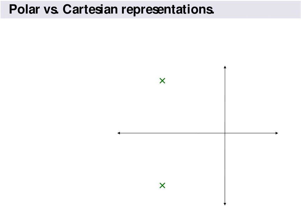
7 Polar vs. Cartesian representations.
8 Polar vs. Cartesian representations. System transfer function : All 4 cases Unless overdamped Cartesian overdamped Significance of the damping ratio : Overdamped Critically damped Underdamped Undamped

9 Polar vs. Cartesian representations. System transfer function : All 4 cases Unless overdamped Cartesian overdamped Significance of the damping ratio : Overdamped Critically damped Underdamped Undamped

10 Polar vs. Cartesian representations. System transfer function : All 4 cases Unless overdamped Cartesian overdamped Significance of the damping ratio : Overdamped Critically damped Underdamped Overdamped case: Undamped

11 Impulse response :

12 Increasing / Fixed Impulse Response.8.6 Amplitude Time (sec)
")
13 Increasing / Fixed Impulse Response.8.6 Amplitude Time (sec)
")
14 Increasing / Fixed Impulse Response.8.6 Amplitude Time (sec)
")
15 Increasing / Fixed Impulse Response.8.6 Amplitude Time (sec)
")
16 Increasing / Fixed. Impulse Response Amplitude Time (sec)
")
17 Increasing / Fixed. Impulse Response Amplitude Time (sec)
")
18 Increasing / Fixed. Impulse Response Amplitude Time (sec)
")
19 Increasing / Fixed. Impulse Response Amplitude Time (sec)
")
20 Increasing / Fixed 6 Impulse Response 5 4 Amplitude Time (sec)
 5-5 -")
21 Increasing / Fixed 6 Impulse Response 5 4 Amplitude Time (sec)
22 Increasing / Fixed 6 Impulse Response 5 4 Amplitude Time (sec)
23 Increasing / Fixed 6 Impulse Response 5 4 Amplitude Time (sec)
24 Increasing / Fixed 5 Impulse Response 4 3 Amplitude Time (sec)
25 Increasing / Fixed 5 Impulse Response 4 3 Amplitude Time (sec)
26 Increasing / Fixed 5 Impulse Response 4 3 Amplitude Time (sec)
27 Increasing / Fixed 5 Impulse Response 4 3 Amplitude Time (sec)
28 Second order step response Underdamped and Undamped output +j5 zeta= time sec. +j5 zeta= j5 zeta= 5 time sec. time sec. time sec..+j output +j.5 zeta=.998 +j.5 zeta= j.5 zeta=.+j time sec. time sec. time sec. time sec.
29 Higher frequency oscillations Faster response Slower response Unstable Lower frequency oscillations
30 Less damping More damping Unstable
31 Second order step response Time specifications
32 Second order step response Time specifications..4 Steady state value. Time to reach first peak (undamped or underdamped only). % of in excess of. Time to reach and stay within % of. Time to rise from % to 9% of
33 Second order step response Time specifications. Steady state value. More generally, if the numerator is not, but some :
34 Second order step response Time specifications. Peak time. Therefore, is the time of the occurrence of the first peak :
Second Order Systems
 Second Order Systems Second Order Equations Standard Form G () s = τ s K + ζτs + 1 K = Gain τ = Natural Period of Oscillation ζ = Damping Factor (zeta) Note: this has to be 1.0!!! Corresponding Differential
Slide 1 / 26. Inductance. 2011 by Bryan Pflueger
 Slide 1 / 26 Inductance 2011 by Bryan Pflueger Slide 2 / 26 Mutual Inductance If two coils of wire are placed near each other and have a current passing through them, they will each induce an emf on one
Finance 30220 Solutions to Problem Set #3. Year Real GDP Real Capital Employment
 Finance 00 Solutions to Problem Set # ) Consider the following data from the US economy. Year Real GDP Real Capital Employment Stock 980 5,80 7,446 90,800 990 7,646 8,564 09,5 Assume that production can
! n. Problems and Solutions Section 1.5 (1.66 through 1.74)
") Problems and Solutions Section.5 (.66 through.74).66 A helicopter landing gear consists of a metal framework rather than the coil spring based suspension system used in a fixed-wing aircraft. The vibration
Problems and Solutions Section.5 (.66 through.74).66 A helicopter landing gear consists of a metal framework rather than the coil spring based suspension system used in a fixed-wing aircraft. The vibration
Understanding Poles and Zeros
 MASSACHUSETTS INSTITUTE OF TECHNOLOGY DEPARTMENT OF MECHANICAL ENGINEERING 2.14 Analysis and Design of Feedback Control Systems Understanding Poles and Zeros 1 System Poles and Zeros The transfer function
3.2 Sources, Sinks, Saddles, and Spirals
 3.2. Sources, Sinks, Saddles, and Spirals 6 3.2 Sources, Sinks, Saddles, and Spirals The pictures in this section show solutions to Ay 00 C By 0 C Cy D 0. These are linear equations with constant coefficients
Structural Dynamics, Dynamic Force and Dynamic System
 Structural Dynamics, Dynamic Force and Dynamic System Structural Dynamics Conventional structural analysis is based on the concept of statics, which can be derived from Newton s 1 st law of motion. This
Let s examine the response of the circuit shown on Figure 1. The form of the source voltage Vs is shown on Figure 2. R. Figure 1.
 Examples of Transient and RL Circuits. The Series RLC Circuit Impulse response of Circuit. Let s examine the response of the circuit shown on Figure 1. The form of the source voltage Vs is shown on Figure.
1.2 Second-order systems
 1.2. SECOND-ORDER SYSTEMS 25 if the initial fluid height is defined as h() = h, then the fluid height as a function of time varies as h(t) = h e tρg/ra [m]. (1.31) 1.2 Second-order systems In the previous
Chapter 30 Inductance
 Chapter 30 Inductance - Mutual Inductance - Self-Inductance and Inductors - Magnetic-Field Energy - The R- Circuit - The -C Circuit - The -R-C Series Circuit . Mutual Inductance - A changing current in
Review of First- and Second-Order System Response 1
 MASSACHUSETTS INSTITUTE OF TECHNOLOGY DEPARTMENT OF MECHANICAL ENGINEERING 2.151 Advanced System Dynamics and Control Review of First- and Second-Order System Response 1 1 First-Order Linear System Transient
Step response of an RLC series circuit
 School of Engineering Department of Electrical and Computer Engineering 332:224 Principles of Electrical Engineering II Laboratory Experiment 5 Step response of an RLC series circuit 1 Introduction Objectives
Technical Guide No. 100. High Performance Drives -- speed and torque regulation
 Technical Guide No. 100 High Performance Drives -- speed and torque regulation Process Regulator Speed Regulator Torque Regulator Process Technical Guide: The illustrations, charts and examples given in
Soil Dynamics Prof. Deepankar Choudhury Department of Civil Engineering Indian Institute of Technology, Bombay
 Soil Dynamics Prof. Deepankar Choudhury Department of Civil Engineering Indian Institute of Technology, Bombay Module - 2 Vibration Theory Lecture - 8 Forced Vibrations, Dynamic Magnification Factor Let
Case Studies on Paper Machine Vibration Problems
 Case Studies on Paper Machine Vibration Problems Andrew K. Costain, B.Sc.Eng. Bretech Engineering Ltd., 70 Crown Street, Saint John, NB Canada E2L 3V6 email: andrew.costain@bretech.com website: www.bretech.com
2.6 The driven oscillator
 2.6. THE DRIVEN OSCILLATOR 131 2.6 The driven oscillator We would like to understand what happens when we apply forces to the harmonic oscillator. That is, we want to solve the equation M d2 x(t) 2 + γ
ACOUSTIC CAVITIES DESIGN PROCEDURES
 ACOUSTIC CAVITIES DESIGN PROCEDURES A. Santana Jr. a, M. S. Silva b, P. T. Lacava. b, and L. C. S. Góes b a Instituto de Aeronáutica e Espaço Divisão de Sistemas Espaciais CP. 12228-94, São José Campos,
12.4 UNDRIVEN, PARALLEL RLC CIRCUIT*
 + v C C R L - v i L FIGURE 12.24 The parallel second-order RLC circuit shown in Figure 2.14a. 12.4 UNDRIVEN, PARALLEL RLC CIRCUIT* We will now analyze the undriven parallel RLC circuit shown in Figure
VCO Phase noise. Characterizing Phase Noise
 VCO Phase noise Characterizing Phase Noise The term phase noise is widely used for describing short term random frequency fluctuations of a signal. Frequency stability is a measure of the degree to which
AN11160. Designing RC snubbers
 AN60 Rev. 25 April 202 Application note Document information Info Keywords Abstract Content RC snubber, commutation, reverse recovery, leakage inductance, parasitic capacitance, RLC circuit and damping,
Simple Vibration Problems with MATLAB (and Some Help from MAPLE) Original Version by Stephen Kuchnicki
 Original Version by Stephen Kuchnicki") Simple Vibration Problems with MATLAB (and Some Help from MAPLE) Original Version by Stephen Kuchnicki December 7, 29 Contents Preface ix 1 Introduction 1 2 SDOF Undamped Oscillation 3 3 A Damped SDOF
Simple Vibration Problems with MATLAB (and Some Help from MAPLE) Original Version by Stephen Kuchnicki December 7, 29 Contents Preface ix 1 Introduction 1 2 SDOF Undamped Oscillation 3 3 A Damped SDOF
Hemodynamic Monitoring: Principles to Practice M. L. Cheatham, MD, FACS, FCCM
 SUMMARY HEMODYNAMIC MONITORING: FROM PRINCIPLES TO PRACTICE Michael L. Cheatham, MD, FACS, FCCM Director, Surgical Intensive Care Units Orlando Regional Medical Center Orlando, Florida Fluid-filled catheters
Vibration Course Enhancement through a Dynamic MATLAB Graphic User Interface
 Vibration Course Enhancement through a Dynamic MATLAB Graphic User Interface Elizabeth K. Ervin 1 [Weiping Xu 2 ] Abstract From the string of a guitar to the radio wave, vibration occurs all the time and
10.450 Process Dynamics, Operations, and Control Lecture Notes - 11 Lesson 11. Frequency response of dynamic systems.
 Lesson. Frequency response of dynamic systems..0 Context We have worked with step, pulse, and sine disturbances. Of course, there are many sine disturbances, because the applied frequency may vary. Surely
The simulation of machine tools can be divided into two stages. In the first stage the mechanical behavior of a machine tool is simulated with FEM
 1 The simulation of machine tools can be divided into two stages. In the first stage the mechanical behavior of a machine tool is simulated with FEM tools. The approach to this simulation is different
Inrush Current. Although the concepts stated are universal, this application note was written specifically for Interpoint products.
 INTERPOINT Although the concepts stated are universal, this application note was written specifically for Interpoint products. In today s applications, high surge currents coming from the dc bus are a
VCO K 0 /S K 0 is tho slope of the oscillator frequency to voltage characteristic in rads per sec. per volt.
 Phase locked loop fundamentals The basic form of a phase locked loop (PLL) consists of a voltage controlled oscillator (VCO), a phase detector (PD), and a filter. In its more general form (Figure 1), the
Power System review W I L L I A M V. T O R R E A P R I L 1 0, 2 0 1 3
 Power System review W I L L I A M V. T O R R E A P R I L 1 0, 2 0 1 3 Basics of Power systems Network topology Transmission and Distribution Load and Resource Balance Economic Dispatch Steady State System
Oscillations. Vern Lindberg. June 10, 2010
 Oscillations Vern Lindberg June 10, 2010 You have discussed oscillations in Vibs and Waves: we will therefore touch lightly on Chapter 3, mainly trying to refresh your memory and extend the concepts. 1
Sensor Performance Metrics
 Sensor Performance Metrics Michael Todd Professor and Vice Chair Dept. of Structural Engineering University of California, San Diego mdtodd@ucsd.edu Email me if you want a copy. Outline Sensors as dynamic
Current Loop Tuning Procedure. Servo Drive Current Loop Tuning Procedure (intended for Analog input PWM output servo drives) General Procedure AN-015
 General Procedure AN-015") Servo Drive Current Loop Tuning Procedure (intended for Analog input PWM output servo drives) The standard tuning values used in ADVANCED Motion Controls drives are conservative and work well in over 90%
Servo Drive Current Loop Tuning Procedure (intended for Analog input PWM output servo drives) The standard tuning values used in ADVANCED Motion Controls drives are conservative and work well in over 90%
Part IB Paper 6: Information Engineering LINEAR SYSTEMS AND CONTROL Dr Glenn Vinnicombe HANDOUT 3. Stability and pole locations.
 Part IB Paper 6: Information Engineering LINEAR SYSTEMS AND CONTROL Dr Glenn Vinnicombe HANDOUT 3 Stability and pole locations asymptotically stable marginally stable unstable Imag(s) repeated poles +
Spring Simple Harmonic Oscillator. Spring constant. Potential Energy stored in a Spring. Understanding oscillations. Understanding oscillations
 Spring Simple Harmonic Oscillator Simple Harmonic Oscillations and Resonance We have an object attached to a spring. The object is on a horizontal frictionless surface. We move the object so the spring
Dynamic Stability. Chapter 5. 5.1 Mathematical Background. 5.1.1 An Introductory Example
 Chapter 5 Dynamic Stability These notes provide a brief background for the response of linear systems, with application to the equations of motion for a flight vehicle. The description is meant to provide
Equivalent Spring Stiffness
 Module 7 : Free Undamped Vibration of Single Degree of Freedom Systems; Determination of Natural Frequency ; Equivalent Inertia and Stiffness; Energy Method; Phase Plane Representation. Lecture 13 : Equivalent
TwinCAT NC Configuration
 TwinCAT NC Configuration NC Tasks The NC-System (Numeric Control) has 2 tasks 1 is the SVB task and the SAF task. The SVB task is the setpoint generator and generates the velocity and position control
Engineering Feasibility Study: Vehicle Shock Absorption System
 Engineering Feasibility Study: Vehicle Shock Absorption System Neil R. Kennedy AME40463 Senior Design February 28, 2008 1 Abstract The purpose of this study is to explore the possibilities for the springs
Applications of Second-Order Differential Equations
 Applications of Second-Order Differential Equations Second-order linear differential equations have a variety of applications in science and engineering. In this section we explore two of them: the vibration
Engineering Sciences 22 Systems Summer 2004
 Engineering Sciences 22 Systems Summer 24 BODE PLOTS A Bode plot is a standard format for plotting frequency response of LTI systems. Becoming familiar with this format is useful because: 1. It is a standard
Joints - Rolls-Royce Perspective
 Joints - Rolls-Royce Perspective Dr John Schofield / Dr Jeff Green Joints Workshop April 2009. 2009 Rolls-Royce plc The information in this document is the property of Rolls-Royce plc and may not be copied
7. Beats. sin( + λ) + sin( λ) = 2 cos(λ) sin( )
 + sin( λ) = 2 cos(λ) sin( )") 34 7. Beats 7.1. What beats are. Musicians tune their instruments using beats. Beats occur when two very nearby pitches are sounded simultaneously. We ll make a mathematical study of this effect, using
34 7. Beats 7.1. What beats are. Musicians tune their instruments using beats. Beats occur when two very nearby pitches are sounded simultaneously. We ll make a mathematical study of this effect, using
Physics of Invasive Blood Pressure Monitoring
 Physics of Invasive Blood Pressure Monitoring IM Moxham Medunsa Study: Physics of Invasive Blood Pressure Monitoring Introduction Intra-arterial cannulation allows for continuous, beat-to-beat blood pressure
Physics 231 Lecture 15
 Physics 31 ecture 15 Main points of today s lecture: Simple harmonic motion Mass and Spring Pendulum Circular motion T 1/f; f 1/ T; ω πf for mass and spring ω x Acos( ωt) v ωasin( ωt) x ax ω Acos( ωt)
Using the Impedance Method
 Using the Impedance Method The impedance method allows us to completely eliminate the differential equation approach for the determination of the response of circuits. In fact the impedance method even
Unit - 6 Vibrations of Two Degree of Freedom Systems
 Unit - 6 Vibrations of Two Degree of Freedom Systems Dr. T. Jagadish. Professor for Post Graduation, Department of Mechanical Engineering, Bangalore Institute of Technology, Bangalore Introduction A two
DYNAMIC ANALYSIS ON STEEL FIBRE
 International Journal of Civil Engineering and Technology (IJCIET) Volume 7, Issue 2, March-April 2016, pp. 179 184, Article ID: IJCIET_07_02_015 Available online at http://www.iaeme.com/ijciet/issues.asp?jtype=ijciet&vtype=7&itype=2
Abstract. Cycle Domain Simulator for Phase-Locked Loops
 Abstract Cycle Domain Simulator for Phase-Locked Loops Norman James December 1999 As computers become faster and more complex, clock synthesis becomes critical. Due to the relatively slower bus clocks
Chapter 5. System security and ancillary services
 Chapter 5. System security and ancillary services 1 Introduction Markets for electrical energy can function only if they are supported by the infrastructure of a power system. System should continue to
Aeroelastic Investigation of the Sandia 100m Blade Using Computational Fluid Dynamics
 Aeroelastic Investigation of the Sandia 100m Blade Using Computational Fluid Dynamics David Corson Altair Engineering, Inc. Todd Griffith Sandia National Laboratories Tom Ashwill (Retired) Sandia National
FREQUENCY RESPONSE ANALYZERS
 FREQUENCY RESPONSE ANALYZERS Dynamic Response Analyzers Servo analyzers When you need to stabilize feedback loops to measure hardware characteristics to measure system response BAFCO, INC. 717 Mearns Road
AN-1012: Reverse Recovery Time (T RR ) of the Super Barrier Rectifier TM Applications Department, APD Semiconductor, San Jose CA
 of the Super Barrier Rectifier TM Applications Department, APD Semiconductor, San Jose CA") AN-1012: Reverse Recovery Time (T RR ) of the Super Barrier Rectifier TM Applications Department, APD Semiconductor, San Jose CA There are many elements to a Reverse Recovery Time (T RR ) waveform and
AN-1012: Reverse Recovery Time (T RR ) of the Super Barrier Rectifier TM Applications Department, APD Semiconductor, San Jose CA There are many elements to a Reverse Recovery Time (T RR ) waveform and
Unsteady Pressure Measurements
 Quite often the measurements of pressures has to be conducted in unsteady conditions. Typical cases are those of -the measurement of time-varying pressure (with periodic oscillations or step changes) -the
AN437 Application note
 Application note C snubber circuit design for TIA Introduction When a TIAC controls inductive loads, the mains voltage and the load current are not in phase. To limit the slope of the reapplied voltage
OPERATIONAL AMPLIFIERS. o/p
 OPERATIONAL AMPLIFIERS 1. If the input to the circuit of figure is a sine wave the output will be i/p o/p a. A half wave rectified sine wave b. A fullwave rectified sine wave c. A triangular wave d. A
Tracking GPS Radio Occultation Signals in the Lower Troposphere: CHAMP Observations and Simulation Studies
 GRAS SAF Open Loop Workshop Helsingør, Denmark June 6-8, 2005 DMI Technical Report 05-11 ISSN: 1399-1388 Kent B. Lauritsen and Frans Rubek, editors Tracking GPS Radio Occultation Signals in the Lower Troposphere:
Input and Output Capacitor Selection
 Application Report SLTA055 FEBRUARY 2006 Input and Output Capacitor Selection Jason Arrigo... PMP Plug-In Power ABSTRACT When designing with switching regulators, application requirements determine how
Advantages of Auto-tuning for Servo-motors
 Advantages of for Servo-motors Executive summary The same way that 2 years ago computer science introduced plug and play, where devices would selfadjust to existing system hardware, industrial motion control
PHASOR DIAGRAMS HANDS-ON RELAY SCHOOL WSU PULLMAN, WA. RON ALEXANDER - BPA
 PHASOR DIAGRAMS HANDS-ON RELAY SCHOOL WSU PULLMAN, WA. RON ALEXANDER - BPA What are phasors??? In normal practice, the phasor represents the rms maximum value of the positive half cycle of the sinusoid
Oscillation Monitoring System
 Oscillation Monitoring System Mani V. Venkatasubramanian Washington State University Pullman WA Oscillation Monitoring System IEEE C37.118 Real-time PMU data stream TCP or UDP OpenPDC OMS SQL server OMS
CBS RECORDS PROFESSIONAL SERIES CBS RECORDS CD-1 STANDARD TEST DISC
 CBS RECORDS PROFESSIONAL SERIES CBS RECORDS CD-1 STANDARD TEST DISC 1. INTRODUCTION The CBS Records CD-1 Test Disc is a highly accurate signal source specifically designed for those interested in making
Series AMLDL-Z Up to 1000mA LED Driver
 FEATURES: Click on Series name for product info on aimtec.com Series Up to ma LED Driver Models Single output Model Input Voltage (V) Step Down DC/DC LED driver Operating Temperature range 4ºC to 85ºC
Inductive sensors. Compact, fast, reliable. Edition 2013
 Inductive sensors. Compact, fast, reliable. Edition 2013 Indispensable in all machines Non-contacting, inductive proximity sensors play a major role in automation technology all over the world. For several
HITACHI INVERTER SJ/L100/300 SERIES PID CONTROL USERS GUIDE
 HITACHI INVERTER SJ/L1/3 SERIES PID CONTROL USERS GUIDE After reading this manual, keep it for future reference Hitachi America, Ltd. HAL1PID CONTENTS 1. OVERVIEW 3 2. PID CONTROL ON SJ1/L1 INVERTERS 3
Introduction to Complex Numbers in Physics/Engineering
 Introduction to Complex Numbers in Physics/Engineering ference: Mary L. Boas, Mathematical Methods in the Physical Sciences Chapter 2 & 14 George Arfken, Mathematical Methods for Physicists Chapter 6 The
EE 402 RECITATION #13 REPORT
 MIDDLE EAST TECHNICAL UNIVERSITY EE 402 RECITATION #13 REPORT LEAD-LAG COMPENSATOR DESIGN F. Kağan İPEK Utku KIRAN Ç. Berkan Şahin 5/16/2013 Contents INTRODUCTION... 3 MODELLING... 3 OBTAINING PTF of OPEN
SEMICONDUCTOR lasers with optical feedback have
 IEEE JOURNAL OF QUANTUM ELECTRONICS, VOL. 34, NO. 10, OCTOBER 1998 1979 Dynamics and Linear Stability Analysis in Semiconductor Lasers with Phase-Conjugate Feedback Atsushi Murakami and Junji Ohtsubo,
Degree Production by Level, Sector, and Major
 Degree Production by Level, Sector, and Major Ohio Compared to the U.S., 1980-2005 August 18, 2006 Table of Contents I. Ohio Degree Production Trends by Sector Page 1 Chart 1. Ohio Trends by Degree Level
Rectifier circuits & DC power supplies
 Rectifier circuits & DC power supplies Goal: Generate the DC voltages needed for most electronics starting with the AC power that comes through the power line? 120 V RMS f = 60 Hz T = 1667 ms) = )sin How
Dynamic Analysis of the Dortmund University Campus Sky Train
 Dynamic Analysis of the Dortmund University Campus Sky Train Reinhold Meisinger Mechanical Engineering Department Nuremberg University of Applied Sciences Kesslerplatz 12, 90121 Nuremberg, Germany Abstract
Automatic Gain Control (AGC) in Receivers
 in Receivers") Automatic Gain Control (AGC) in Receivers Iulian Rosu, YO3DAC / VA3IUL http://www.qsl.net/va3iul/ AGC was implemented in first radios for the reason of fading propagation (defined as slow variations in
Automatic Gain Control (AGC) in Receivers Iulian Rosu, YO3DAC / VA3IUL http://www.qsl.net/va3iul/ AGC was implemented in first radios for the reason of fading propagation (defined as slow variations in
Homework #11 203-1-1721 Physics 2 for Students of Mechanical Engineering
 Homework #11 203-1-1721 Physics 2 for Students of Mechanical Engineering 2. A circular coil has a 10.3 cm radius and consists of 34 closely wound turns of wire. An externally produced magnetic field of
Transcutaneous Electrical Nerve Stimulation Device. Operation Manual Read Before Using
 Transcutaneous Electrical Nerve Stimulation Device Operation Manual Read Before Using TABLE OF CONTENTS INTRODUCTION TO TENS INDICATIONS AND CONTRAINDICATIONS WARNINGS PRECAUTIONS/ADVERSE REACTIONS ABOUT
SIESMIC SLOSHING IN CYLINDRICAL TANKS WITH FLEXIBLE BAFFLES
 SIESMIC SLOSHING IN CYLINDRICAL TANKS WITH FLEXIBLE BAFFLES Kayahan AKGUL 1, Yasin M. FAHJAN 2, Zuhal OZDEMIR 3 and Mhamed SOULI 4 ABSTRACT Sloshing has been one of the major concerns for engineers in
SECTION 2 Transmission Line Theory
 SEMICONDUCTOR DESIGN GUIDE Transmission Line Theory SECTION 2 Transmission Line Theory Introduction The ECLinPS family has pushed the world of ECL into the realm of picoseconds. When output transitions
Active Filters. Motivation:
 Active Filters Motivation: Analyse filters Design low frequency filters without large capacitors Design filters without inductors Design electronically programmable filters Imperial College London EEE
Diode Applications. As we have already seen the diode can act as a switch Forward biased or reverse biased - On or Off.
 Diode Applications Diode Switching As we have already seen the diode can act as a switch Forward biased or reverse biased - On or Off. Voltage Rectifier A voltage rectifier is a circuit that converts an
Lecture 8 : Dynamic Stability
 Lecture 8 : Dynamic Stability Or what happens to small disturbances about a trim condition 1.0 : Dynamic Stability Static stability refers to the tendency of the aircraft to counter a disturbance. Dynamic
FUZZY Based PID Controller for Speed Control of D.C. Motor Using LabVIEW
 FUZZY Based PID Controller for Speed Control of D.C. Motor Using LabVIEW SALIM, JYOTI OHRI Department of Electrical Engineering National Institute of Technology Kurukshetra INDIA salimnitk@gmail.com ohrijyoti@rediffmail.com
Positive Feedback and Oscillators
 Physics 3330 Experiment #6 Fall 1999 Positive Feedback and Oscillators Purpose In this experiment we will study how spontaneous oscillations may be caused by positive feedback. You will construct an active
Department of Electrical and Computer Engineering Ben-Gurion University of the Negev. LAB 1 - Introduction to USRP
 Department of Electrical and Computer Engineering Ben-Gurion University of the Negev LAB 1 - Introduction to USRP - 1-1 Introduction In this lab you will use software reconfigurable RF hardware from National
AND9015. A Solution for Peak EMI Reduction with Spread Spectrum Clock Generators APPLICATION NOTE. Prepared by: Apps Team, BIDC ON Semiconductor
 A Solution for Peak EMI Reduction with Spread Spectrum Clock Generators Prepared by: Apps Team, BIDC ON Semiconductor APPLICATION NOTE Introduction This application note will outline Spread Spectrum Clock
Fluid structure interaction of a vibrating circular plate in a bounded fluid volume: simulation and experiment
 Fluid Structure Interaction VI 3 Fluid structure interaction of a vibrating circular plate in a bounded fluid volume: simulation and experiment J. Hengstler & J. Dual Department of Mechanical and Process
Manufacturing Equipment Modeling
 QUESTION 1 For a linear axis actuated by an electric motor complete the following: a. Derive a differential equation for the linear axis velocity assuming viscous friction acts on the DC motor shaft, leadscrew,
Lecture 1-10: Spectrograms
 Lecture 1-10: Spectrograms Overview 1. Spectra of dynamic signals: like many real world signals, speech changes in quality with time. But so far the only spectral analysis we have performed has assumed
Power Supplies. 1.0 Power Supply Basics. www.learnabout-electronics.org. Module
 Module 1 www.learnabout-electronics.org Power Supplies 1.0 Power Supply Basics What you ll learn in Module 1 Section 1.0 Power Supply Basics. Basic functions of a power supply. Safety aspects of working
Controller Design in Frequency Domain
 ECSE 4440 Control System Engineering Fall 2001 Project 3 Controller Design in Frequency Domain TA 1. Abstract 2. Introduction 3. Controller design in Frequency domain 4. Experiment 5. Colclusion 1. Abstract
Shock test severity based on Shock Response Spectrum
 Shock test severity based on Shock Response Spectrum Frans Assink THALES NEDERLAND B.V. AND/OR ITS SUPPLIERS THIS INFORMATION CARRIER CONTAINS PROPRIETARY INFORMATION WHICH SHALL NOT BE USED, REPRODUCED
Unit2: Resistor/Capacitor-Filters
 Unit2: Resistor/Capacitor-Filters Physics335 Student October 3, 27 Physics 335-Section Professor J. Hobbs Partner: Physics335 Student2 Abstract Basic RC-filters were constructed and properties such as
The full wave rectifier consists of two diodes and a resister as shown in Figure
 The Full-Wave Rectifier The full wave rectifier consists of two diodes and a resister as shown in Figure The transformer has a centre-tapped secondary winding. This secondary winding has a lead attached
MAS.836 HOW TO BIAS AN OP-AMP
 MAS.836 HOW TO BIAS AN OP-AMP Op-Amp Circuits: Bias, in an electronic circuit, describes the steady state operating characteristics with no signal being applied. In an op-amp circuit, the operating characteristic
Chapter 2 Introduction to Rotor Dynamics
 Chapter 2 Introduction to Rotor Dynamics Rotor dynamics is the branch of engineering that studies the lateral and torsional vibrations of rotating shafts, with the objective of predicting the rotor vibrations
How To Solve A Linear Dierential Equation
 Dierential Equations (part 2): Linear Dierential Equations (by Evan Dummit, 2012, v. 1.00) Contents 4 Linear Dierential Equations 1 4.1 Terminology.................................................. 1 4.2
Physical Layer, Part 2 Digital Transmissions and Multiplexing
 Physical Layer, Part 2 Digital Transmissions and Multiplexing These slides are created by Dr. Yih Huang of George Mason University. Students registered in Dr. Huang's courses at GMU can make a single machine-readable
Software Defined Radio
 Software Defined Radio GNU Radio and the USRP Overview What is Software Defined Radio? Advantages of Software Defined Radio Traditional versus SDR Receivers SDR and the USRP Using GNU Radio Introduction
Short-time FFT, Multi-taper analysis & Filtering in SPM12
 Short-time FFT, Multi-taper analysis & Filtering in SPM12 Computational Psychiatry Seminar, FS 2015 Daniel Renz, Translational Neuromodeling Unit, ETHZ & UZH 20.03.2015 Overview Refresher Short-time Fourier
Title: Low EMI Spread Spectrum Clock Oscillators
 Title: Low EMI oscillators Date: March 3, 24 TN No.: TN-2 Page 1 of 1 Background Title: Low EMI Spread Spectrum Clock Oscillators Traditional ways of dealing with EMI (Electronic Magnetic Interference)
Σ _. Feedback Amplifiers: One and Two Pole cases. Negative Feedback:
 Feedback Amplifiers: One and Two Pole cases Negative Feedback: Σ _ a f There must be 180 o phase shift somewhere in the loop. This is often provided by an inverting amplifier or by use of a differential
Inductance and Magnetic Energy
 Chapter 11 Inductance and Magnetic Energy 11.1 Mutual Inductance... 11-3 Example 11.1 Mutual Inductance of Two Concentric Coplanar Loops... 11-5 11. Self-Inductance... 11-5 Example 11. Self-Inductance
SGN-1158 Introduction to Signal Processing Test. Solutions
 SGN-1158 Introduction to Signal Processing Test. Solutions 1. Convolve the function ( ) with itself and show that the Fourier transform of the result is the square of the Fourier transform of ( ). (Hints: