Unit 1 INTRODUCTION 1.1.Introduction 1.2.Objectives
|
|
|
- Beatrix Allison
- 10 years ago
- Views:
Transcription
1 Structure 1.1.Introduction 1.2.Objectives 1.3.Properties of Fluids 1.4.Viscosity 1.5.Types of Fluids. 1.6.Thermodynamic Properties 1.7.Compressibility 1.8.Surface Tension and Capillarity 1.9.Capillarity Summary Keywords Exercise Unit 1 INTRODUCTION 1.1.Introduction Fluid mechanics that branch of science which deals with the behavior of the fluids (liquids orgases) at rest as well as in motion. Thus this branch of science deals with the static, kinematics and dynamic aspects of fluids. The study of fluids at rest is called fluid statics. The study of fluids in motion, where pressure forces are not considered, is called fluid kinematics and if the pressure forces are also considered for the fluids in motion, that branch of science is called fluid dynamics. 1.2.Objectives After studying this unit we are able to understand Properties of Fluids Viscosity Types of Fluids. Thermodynamic Properties Compressibility Surface Tension and Capillarity Capillarity

2 1.3.Properties of Fluids Density or Mass Density Density or mass density of a fluid is defined as the ratio of the mass of a fluid to its volume. Thus mass per unit volume of a fluid is called density. It is denoted the symbol p (rho). The unit of mass density in SI unit is kg per cubic meter, i.e. kg/m3. The density of liquids may be considered as constant while that of gases changes with the variation of pressure and temperature. Mathematically, mass density is written as The value of density for water is 1 gm/cm3 or 1000 kg/m3. Specific Weight or Weight Density Specific weight or weight density of a fluid is the ratio between the weights of a fluid to its volume. Thus weight per unit volume of a fluid is called weight density and it is denoted by the symbol w. Specific Volume Specific Volume of a fluid is defined as the volume of a fluid occupied by a unit measure volume per unit mass of fluid is called specific volume. Mathematically, it is expressed as specific volume Thus specific volume is the reciprocal of mass density. It is expressed on m 3 /kg. It is commonly applied to gases

3 Specific Gravity Specific gravity is defined as the ratio of the weight density (or density) of fluid to the weight density (or density) of a standard fluid. For liquids, the standard fluid is taken water and for gases, the standard fluid is taken air. Specific gravity is also called relative density. It is dimension less quantity and is denoted by the symbol S. Problem 1.1. Calculate the specific weight, density and specific gravity of one liter of a liquid which weighs 7 N. Problem 1.2. Calculate the density, specific weight and weight of one liter of petrol of specific gravity = 0.7.

4 1.4.Viscosity Viscosity is defined as the property of a fluid which offers resistance to the movement of one layer of over another adjacent layer of the fluid. When two layers of a fluid a distance dy apart, move one over the other at a different velocities, say u and u+du as shown in Fig. 1.1, the viscosity together with relative velocity causes a shear stress acting between the flid layers Fig.1.1 Velocity variationnear a solid boundary The top layer causes a shear stress on the adjacent lower layer while the lower layer causes a shear stress on the adjacent top layer. This shear stress is proportional to the rate of change of velocity with respect to y. It is denoted by symbol t called Tau.

5 Units of viscosity The units of viscosity is obtained by putting the dimensions of the quantities in equation (1.3) In MKS system, force is represented by kgf and length by meter (m), in CGS system, force is represented by dyne and length by cm and in SI system force is represented by Newton (N) and length by meter (m). Thus for solving numerical problems, if viscosity is given in poise, it must be divided by 98.1 to get its equivalent numerical value in MKS.


6 Note. (i) In SI units second is represented by 's' and not by 'sec'. (ii) If viscosity is given in poise, it must be divided by 10 to get its equivalent numerical value in SI units. Sometimes a unit of viscosity as centipoise is used where The viscosity of water at 20 C is 0.01poise or 1.0centipoise. Kinematic Viscosity It is defined as the ratio between the dynamic viscosity and density of fluid. It is denoted by the Greek symbol (v) called 'nu'. Thus, mathematically, In MKS and SI, the unit of kinematic viscosity is metre 2 /sec or m 2 /sec while in CGS units it is written as cm 2 /s. In CGS units, kinematic viscosity is also known stoke.
 called 'nu'.")

7 Newton's Law of Viscosity It states that the shear stress (T) on a fluid element layer is directly proportional to the rate of shear strain. The constant of proportionality is called the co-efficient of viscosity. Mathematically, it is expressed as given by equation (1.2) or as Fluids which obey the above relation are known as Newtonian fluids and the fluids which do no: obey the above relation are called Non-newtonian fluids. Variation of Viscosity with Temperature Temperature affects the viscosity. 'The viscosity of liquids decreases with the increase of temperature while the viscosity of gases increases with the increase of temperature. This is due to reason that in liquids the cohesive forces predominates the molecular momentum transfer, due to closely packed molecules and with the increase in temperature, the cohesive forces decreases with the result of decreasing viscosity. But in case of gases the cohesive force are small and molecular momentum transfer predominates. With the increase in temperature, molecular momentum transfer increases and hence viscosity increases. The relation between viscosity and temperature for liquids gases are: 1.5.Types of Fluids

8 Fig. 1.2 Type of fluids The fluids may be classified into the following five types: (1). Ideal fluid, (2) Real fluid, (3) Newtonian fluid, (4) Non-Newtonian fluid, and (5) Ideal plastic fluid. 1. Ideal Fluid : A fluid, which is incompressible and is having no viscosity, is known as an ideal fluid. Ideal fluid is only an imaginary fluid as al1 the fluids, which exist, hive some viscosity. 2. Real Fluid. A fluid, which possesses viscosity. is known as real fluid. All the fluids, in actual practice., are real fluids. 3. Newtonian Fluid. A real' fluid, in which the shear stress is directly, proportional to the rate of shear strain (or velocity gradient) is known as Newtonian fluid. 4. Non-Newtonian Fluid. A real fluid, in which the shear stress is not proportional to the rate of shear strain (or velocity gradient) is known as a Non-Newtonian fluid. 5. Ideal Plastic Fluid. A fluid,. in which shear stress is more than the yield value and shear stress is proportional -Velocity gradient (&) to the rate of shear strain (or velocity gradient)is, known as d Y ideal plastic fluid. Problem: 1.3. If the velocity distribution over a plate is given by u = 2/3y y 2 - in which u is tile velocity in meter per second at a distance y meter above the plate, determine the shear stress at y = 0 and y = 0.15 m. Take dynamic viscosity of fluid as 8.63 poises.
 is known as Newtonian fluid. 4. Non-Newtonian Fluid.")
9 Problem 1.4. A plate, mm distant from a fixed plate, moves at 60 cm/s and requires a force of 2N per unit area i.e. 2N/m 2 to maintain this speed Determine the fluid viscosity between the plates. Problem 1.5 A flat plate of area 1.5 x lo6 mm2 is pulled with a speed of 0.4 m/s relative to another plate located at a distance of 0.15 mm from it. Find the force and power required to maintain this speed, if the fluid separating them is having viscosity as 1poise

10 Problem 1.6. Determine the intensity of shear of an oil having viscosity = 1 poise. The oil is used for lubricating the clearance between a shaft of diameter 10 cm and its journal bearing. The clearance is 1.5 mm and the shaft rotates at 150 r.p.m. Problem 1.7. Calculate the dynamic viscosity of an oil, which is used for lubrication between a square plate of size 0.8 m x 0.8 m and an inclined plane with angle of inclination 3(P as shown in Fig The weight of the square plate is 300 N and it slides down the inclined plane with a uniform velocity of 0.3 m/s. The thickness of oil film is 1.5 mm.


11 1.6.Thermodynamic Properties Fluids consist of liquids or gases. But gases are compressible fluids and hence thermodynamic properties play an important role. With the change of pressure and temperature, the gases undergo large variation in density. The relationship between pressure (absolute), specific volume and temperature (absolute) of a gas is given by the equation of state as Dimension of R. the gas constant R depends upon the particular gas. The dimension of R is obtained from equation (1.5) as
, specific volume and temperature (absolute) of a gas is given by the equation of")
12 Isothermal Process. If the changes in density occurs at constant temperature, the process is called isothermal and relationship between (p) and density (P) is given by Adiabatic Process. If the change in density occurs with no heat exchange to and may the gas, the process is called adiabatic. And if no heat is generates within the gas due to friction, the relationship between pressure and density is given by Where k = Ratio of specific heat of a gas at constant pressure and constant volume = 1.4 for air Universal Gas Constant. Let m = Mass of a gas in kg V = Volume of gas of mass m p = Absolute pressure T = Absolute temperature Then, we have Where R = Gas constant. Equation (1.8) can be made universal, i.e. applicable to all gases if it is expressed in molebasis. Let n = Number of moles in volume of a gas V = Volume of the gas M= Mass of the gas molecules Mass of a hydrogen atom m = Mass of a gas in kg P Then, we have n x M = m.

13 Substituting the value of m in equation (1.8), we get The product M x R is called universal gas constant and is equal to In MKS units and 8314/kg-mole K in SI units. One kilogram mole is defined as the product of one kilogram mass of the gas and its molecular weight Problem A gas weighs 16 N/m 3 at 25 o C and at an absolute pressure of 0.25 N/mm 2. Determine the gas constant and density of the gas. Sol. Given : Weight density, w = 16 N/m2 Temperature, t = 25 C T=273 +t= =288 o K p = 0.25 N/mm 2 (abs.) = 0.25 x l0 6 N/m 2 = 25 x l0 4 N/m 2 (i) Using relation w = pg, density is obtained as (ii) Using equation (1.5) Problem 1.8.A cylinder of 0.6 m3 in volume contains air at 50 C and 0.3 Nlmm2 absolute pressure. The air is compressed to 0.3 m3. Find (i) pressure inside the cylinder assuming isothermal process and (ii) pressure and temperature assuming adiabatic process. Take k = 1.4.
 Using relation w = pg, density is obtained as (ii) Using equation (1.5) Problem 1.8.A cylinder of 0.6 m3 in volume contains air at 50 C and 0.")
14 Problem 1.9 Calculate the pressure exerted by 5 kg of nitrogen gas at a temperature of 10 C if the volume is 0.4 m 3. Molecular weight of nitrogen is 28. Assume, ideal gas laws are applicable. Sol. Given : Mass of nitrogen =5kg Temperature, t = 10 C.. T = = 283 K Volume of nitrogen, V = 0.4 m3 Molecular weight = 28 Using equation (1.9), we have p = n x M x RT


15 1.7.Compressibility Compressibility is the reciprocal of the bulk modulus of elasticity, K which is defined as the ratio of compressive stress to volumetric strain. Consider a cylinder fitted with a piston as shown in Fig. 1.3 Fig. 1.3 Consider a cylinder fitted with a piston as shown in Fig Let = Volume of a gas enclosed in the cylinder p = Pressure of gas when volume is Let the pressure is increased top + dp, the volume of gas decreases from to - d Then increase in pressure = dp kgf/m 2 Decrease in volume =d Relationship between K and Pressure (p) for a Gas The relationship between bulk modulus of elasticity (K) and pressure for a gas for two different processes of compression are as : (i) For Isothermal Process. Equation (1.6) gives the relationship between pressure (p) and density (P) of a gas as


16 Problem Determine the bulk modulus of elasticity of a liquid, if the pressure of the liquid is Increased from 70 Nlcm 2 to 130 Nlcm 2 The volume of the liquid decreases by 0.15per cent Sol. Given : Initial pressure = 70 N/cm 2 Final pressure = 130 N/cm 2 Therefore dp = Increase in pressure = = 60 N/cm 2 Decrease in volume = 0.15% Problem What is the bulk modulus of elasticity of a liquid which is compressed in a cylinder from Compressibility is given by - -1 a volume of m 3 at 80 N/m 3 pressure to a volume of m 3 at 150N/cm 3 pressure.


17 1.8.Surface Tension and Capillarity Surface tension is defined as the tensile force acting on the surface of a liquid in contact with a gas or on the surface between two immiscible liquids such that the contact surface behaves like a membrane under tension. The magnitude of this force per unit length of the free surface will have the same value as the surface energy per unit area. It is denoted by Greek letter a (called sigma). In MKS units, it is expressed as kgf/m while in SI units as N/m. The phenomenon of surface tension is explained by Fig Consider three molecules A, B, C of a liquid in a mass of liquid. The molecules A is attracted in all directions equally by the surrounding molecules of the liquid. Thus the resultant force acting on the molecule A is zero. But the molecule B, which is situated near the free surface, is acted upon by upward and downward forces which are unbalanced. Thus a net resultant force on molecule B is acting in the downward direction. The molecule C, situated on the free surface of liquid does experience a resultant downward force. All the molecules on the free surface experience a downward force. Thus the free surface of the liquid acts like a very thin film under tension of the surface of the liquid acts as though it is an elastic membrane under tension. Fig.1.4: Surface tension

18 Surface Tension on Liquid Droplet Consider a small spherical droplet of a liquid of radius 'r'. On the entire surface of the droplet, the tensile force due to surface tension will be acting. Let a = Surface tension of the liquid p = Pressure intensity inside the droplet (in excess of the outside pressure intensity) d = Dia. of droplet. Surface Tension on a Hollow Bubble. A hollow bubble like a soap bubble in air his two surfaces in contact with air, one inside and other outside. Thus two surfaces are subjected to surface tension. In such case, we bave Surface Tension on a Jet. Consider a liquid jet of diameter 'd' and length 2' as shown in Fig Fig.1.5: Forces on liquid jet

19 Let p = Pressure intensity inside the liquid jet above the outside pressure a = Surface tension of the liquid. Consider the equilibrium of the semi jet, we have Force due to pressure = p x area of semi jet = p x L x d Force due to surface tension = a x 2L. Equating the forces, we have Problem The surface tension of water in contact with air at 20 C is N/m. The pressure inside a droplet of water is to be 0.02 N/cm2 greater than the outside pressure. Calculate the diameter of the droplet of water. Problem The pressure outside the droplet of water of diameter 0.04 mm is N/cm 2 (atmospheric pressure). Calculate the pressure within the droplet if surface tension k given as N/m of water.


20 1.9.Capillarity Capillarity is defined as a phenomenon of rise or fall of a liquid surface in a small tube relative to the adjacent general level of liquid when the tube is held vertically in the liquid. The rise of liquid surface is known as capillary rise while the fall of the liquid surface is known as capillary depression. It is expressed in terms of cm or mm of liquid. Its value depends upon the specific weight of the liquid, diameter of the tube and surface tension of the liquid. Expression for Capillary Rise Consider a glass tube of small diameter d opened at both ends and is inserted in a liquid, say water. The liquid will rise in the tube above the level of the liquid. Let h = height of the liquid in the tube. Under a state of equilibrium, the weight of liquid of height h is balanced by the force at the surface of the liquid in the tube. But the force at the surface of the liquid in the tube is due to surface tension. Fig.1.6 Capillary rise Let σ = Surface tension of liquid Θ = Angle of contact between liquid and glass tube. The weight of the liquid of height h in the tube =(Area of the tube x h) x p x g =π/4 d 2 x h x p x g.(1.17) Where p = Density of liquid


21 The value of θ between water and clean glass tube is approximately equal to zero and hence cosθ is equal to unity of water is given by Expression for Capillaty Fall. If the glass tube is dipped in mercury, the level of mercury in the tube will be lower than the general level of the outside liquid as shown in Fig Let h = Height of depression in tube. Then in equilibrium, two forces are acting on the mercury inside the tube. First one is due to surface tension acting in the downward direction and is equal to a x πd x cosθ Second force is due to hydrostatic force acting upward and is equal to intensity of pressure at a depth 'h' x Area Problem Calculate the capillary rise in a glass tube of2.5 mm diameter when immersed vertically in (a) water and (b) mercury. Take surface tensions o = N/m for water and O=0.52N/m for mercury in contact with air. The specific gravity mercury is given as 13.6 and angle of contact = 130".
22 Problem Calculate the capillary effect in millimeters in a glass tube of 4 mm diameter, when immersed in (i) water, and (ii) mercury. The temperature of the liquid is 20 C and the values of the surface tension of water and mercury at 20 C in contact with air are N/m and 0.51 N/m respectively. The angle of contact for water is zero that for mercury 1.30". Take density of water at 20 C as equal to 998 kg/m 3. Problem 1.16: The capillary rise in the glass tube is not to exceed 0.2 mm of water. Determine its minimum size, given that surface tension for water in contact with air = N/m.
23 Thus minimum diameter of the tube should be 14.8cm.
24 1.10. Summary In this unit we have studied Properties of Fluids Viscosity Types of Fluids. Thermodynamic Properties Compressibility Surface Tension and Capillarity Capillarity Keywords Viscosity Kinematic Viscosity Ideal Fluid Compressibility Capillarity Real Fluid Newtonian Fluid Non-Newtonian Fluid Ideal Plastic Fluid Exercise 1. Define the following fluid properties Density, Weight density, Specific volume and specific gravity of a fluid. 2. Differentiate between : (i) liquids and gases, (ii) Real fluids and ideal fluids, (iii) Specific weight and specific volume of a fluid. 3. What is the difference between dynamic viscosity and kinematic viscosity? State their units of measurements. 4. Explain the terms: (i) dynamic viscosity and (ii) kinematic viscosity. Give their dimensions. 5. State the Newton's law of viscosity and give examples of its application.
25 6. Enunciate Newton's law of viscosity. Explain the importance of viscosity in fluid motion. What is the effect of temperature on viscosity of water and that of air? 7. Define Newtonian and Non-Newtonian fluids. 8. What do you understand by terms : (i) Isothermal process, ( i i ) Adiabatic process, and (iii) Universal-gas constant. 9, Define compressibility. Prove that compressibility for a perfect gas undergoing isothermal compression is P while for a perfect gas undergoing isentropic compression is WP 10. Define surface tension. Prove that the relationship between surface tension and pressure inside a droplet of liquid in excess of outside pressure is given byp = 4σ/d 11. Explain the phenomenon of capillarity. Obtain an expression for capillary rise of a liquid. 12. Distinguish between ideal fluids and real fluids. Explain the importance of compressibility in fluid flow. 13. Define and explain Newton's law of viscosity. 14. Convert 1 kg/s-m dynamic viscosity in poise. 15. Why does the viscosity of a gas increases with the increase in temperature while that of a liquid deceases with increase in temperature? NUMERICAL PROBLEMS 1. One liter of crude oil weighs 9.6 N. Calculate its specific weight, density and specific gravity. 2. The velocity distribution for flow over a Flat plate is given by u = 3/2.y-y 3/2, where u is the point velocity in meter per second at a distance y meter above the plate. Determine the shear stress at y = 9 cm. Assume dynamic viscosity as 8 poise. 3. A plate, mm distant From a fixed plate, moves at 50 cm/s and requires force of N/m 2 maintain this speed. Determine the fluid viscosity between the plates in the poise. 4. Determine the intensity of shear of an oil having viscosity = 1.2 poise and is used for lubrication in the clearance between a 10 cm diameter shaft and its journal bearing. The clearance is 1.0 mm and shaft rotates at 200 r.p.m. 5. Two plates 2 are placed at a distance of 0.15 mm apart. The lower plate is f i e d while the upper plate having surface area 1.0 m is pulled at 0.3 m/s. Find the force and power required to maintain this speed, if the fluid separating them is having viscosity 1.5 poise. 6. An oil film of thickness 1.5 mm is used for lubrication between a square plate of size 0.9m x 0.9 m and an inclined plane having an angle of inclination 20'. The weight of the square
26 plate is N and it slides down the plane with a uniform velocity of 0.2 m/s. Find the dynamic viscosity of the oil. 7. In a stream of glycerin in motion, at a certain point the velocity gradient is 0.25 meter per sec per meter. The mass density of fluid is kg per cubic meter and kinematic viscosity is 6.30 x 10⁴square meter per second. Calculate the shear stress at the point.
27 Unit 2 BERNOULLI EQUATION AND APPLICATIONS Structure 2.1. Introduction 2.2. Objectives 2.3.Forms of Energy Encountered in Fluid Flow 2.4.Variation in the Relative Values of Various Forms of Energy During Flow 2.5.EULER S Equation of Motion for Flow along a Stream Line 2.6.Bernoulli Equation for Fluid Flow 2.7.Energy Line and Hydraulic Gradient Line 2.8.Volume Flow through a Venturimeter 2.9.Euler and Bernoulli Equation for Flow with Friction Concept and Measurement of Dynamic, Static and Total Head Pitot Tube Solved Problems Summary Keywords Exercise 2.1.Introduction In chapter five flow of ideal fluids was discussed. The main idea was the study of flow pattern. The determination of equal flow paths and equal potential lines was discussed. No attempt was made to determine the numerical value of these quantities. In this chapter the method of determination of the various energy levels at different locations in the flow is discussed. In this process first the various forms of energy in the fluid are identified. Applying the law of conservation of energy the velocity, pressure and potential at various locations in the flow are calculated. Initially the study is limited to ideal flow. However the modifications required to apply the analysis to real fluid flows are identified. The material discussed in this chapter are applicable to many real life fluid flow problems. The laws presented are the basis for the design of fluid flow systems.
28 Energy consideration in fluid flow: Consider a small element of fluid in flow field. The energy in the element as it moves in the flow field is conserved. This principle of conservation of energy is used in the determination of flow parameters like pressure, velocity and potential energy at various locations in a flow. The concept is used in the analysis of flow of ideal as well as real fluids. Energy can neither be created nor destroyed. It is possible that one form of energy is converted to another form. The total energy of a fluid element is thus conserved under usual flow conditions. If a stream line is considered, it can be stated that the total energy of a fluid element at any location on the stream line has the same magnitude. 2.2.Objectives After studying this unit we are able to understand Forms of Energy Encountered in Fluid Flow Variation in the Relative Values of Various Forms of Energy During Flow EULER S Equation of Motion for Flow along a Stream Line Bernoulli Equation for Fluid Flow Energy Line and Hydraulic Gradient Line Volume Flow through a Venturimeter Euler and Bernoulli Equation for Flow with Friction Concept and Measurement of Dynamic, Static and Total Head Pitot Tube 2.3.Forms of Energy Encountered in Fluid Flow Energy associated with a fluid element may exist in several forms. These are listed here and the method of calculation of their numerical values is also indicated. Kinetic Energy This is the energy due to the motion of the element as a whole. If the velocity is V, then the kinetic energy for m kg is given by ( 2.1.1) The unit in the SI system will be Nm also called Joule (J) {(kg m 2 /s 2 )/(kg m/n s 2 )}
29 The same referred to one kg (specific kinetic energy) can be obtained by dividing by the mass m and then the unit will be Nm/kg..(2.1.1b) In fluid flow studies, it is found desirable to express the energy as the head of fluid in m. This unit can be obtained by multiplying equation (6.1.1) by g o /g...(2.1.2) Apparently the unit appears as metre, but in reality it is Nm/N, where the denominator is weight of the fluid in N. The equation in this form is used at several places particularly in flow of liquids. But the energy associated physically is given directly only be equation The learner should be familiar with both forms of the equation and should be able to choose and use the proper equation as the situation demands. When different forms of the energy of a fluid element is summed up to obtain the total energy, all forms should be in the same unit. Potential Energy This energy is due to the position of the element in the gravitational field. While a zero value for KE is possible, the value of potential energy is relative to a chosen datum. The value of potential energy is given by PE = mz g/g o Nm (2.1.3) Where m is the mass of the element in kg, Z is the distance from the datum along the gravitational direction, in m. The unit will be (kg m m/s 2 ) (Ns 2 /kgm) i.e., Nm. The specific potential energy (per kg) is obtained by dividing equation by the mass of the element. PE = Z g/g 0 Nm/kg ( b) This gives the physical quantity of energy associated with 1 kg due to the position of the fluid element in the gravitational field above the datum. As in the case of the kinetic energy, the value of PE also is expressed as head of fluid, Z. PE = Z (g/g o ) (g o /g) = Z m. This form will be used in equations, but as in the case of KE, one should be familiar with both the forms and choose the suitable form as the situation demands.
30 Pressure Energy (Also Equals Flow Energy) The element when entering the control volume has to flow against the pressure at that location. The work done can be calculated referring Fig Fig.2.1: Flow work calculation The boundary of the element of fluid considered is shown by the dotted line, Force = P 1 A, distance to be moved = L, work done = P 1 AL = P 1 mv as AL = volume = mass specific volume, v. flow work = P mv. The pressure energy per kg can be calculated using m = 1. The flow energy is given by FE = P.v = P/ρ, Nm/kg As in the other cases, the flow energy can also expressed as head of fluid. As specific weight γ = ρ g/g o, the equation is written as, (2.1.5) (2.1.5b) It is important that in any equation, when energy quantities are summed up consistent forms of these set of equations should be used, that is, all the terms should be expressed either as head of fluid or as energy (J) per kg. These are the three forms of energy encountered more often in flow of incompressible fluids. Internal Energy This is due to the thermal condition of the fluid. This form is encountered in compressible fluid flow. For gases (above a datum temperature) IE = c v T where T is the temperature above the datum temperature and c v is the specific heat of the gas at constant volume. The unit for internal energy is J/kg (Nm/kg). When friction is significant other forms of energy is converted to internal energy both in the case of compressible and incompressible flow.
31 Electrical and Magnetic Energy These are not generally met with in the study of flow of fluids. However in magnetic pumps and in magneto hydrodynamic generators where plasma flow in encountered, electrical and magnetic energy should also be taken into account. 2.4.Variation in the Relative Values of Various Forms of Energy During Flow Under ideal conditions of flow, if one observes the movement of a fluid element along a stream line, the sum of these forms of energy will be found to remain constant. However, there may be an increase or decrease of one form of energy while the energy in the other forms will decrease or increase by the same amount. For example when the level of the fluid decreases, it is possible that the kinetic energy increases. When a liquid from a tank flows through a tap this is what happens. In a diffuser, the velocity of fluid will decrease but the pressure will increase. In a venturimeter, the pressure at the minimum area of cross section (throat) will be the lowest while the velocity at this section will be the highest. The total energy of the element will however remain constant. In case friction is present, a part of the energy will be converted to internal energy which should cause an increase in temperature. But the fraction is usually small and the resulting temperature change will be so small that it will be difficult for measurement. From the measurement of the other forms, it will be possible to estimate the frictional loss by difference. 2.5.EULER S Equation of Motion for Flow along a Stream Line Consider a small element along the stream line, the direction being designated as s. Fig.2.2: Euler s equation of Motion - Derivation
 where a s is the acceleration along the s direction. This reduces to, (2.3.2) (Note: It will be desirable to add go to the first term for dimensional homogeneity.")
32 The net force on the element are the body forces and surface forces (pressure). These are indicated in the figure. Summing this up, and equating to the change in momentum. PdA {P + ( P/ s} da ρg da ds cos θ = ρ da ds as (2.3.1) where a s is the acceleration along the s direction. This reduces to, (2.3.2) (Note: It will be desirable to add go to the first term for dimensional homogeneity. As it is, the first term will have a unit of N/kg while the other two terms will have a unit of m/s 2. Multiplying by go, it will also have a unit of m/s 2 ). and as cos θ = dz/ds, equation reduces to, (2.3.2 a) For steady flow V/ t = 0. Cancelling s and using total derivatives in place of partials as these are independent quantities. (2.3.3) (Note: in equation also it is better to write the first term as go.dp/ρ for dimensional homogeneity). This equation after dividing by g, is also written as, (2.3.4) which means that the quantity within the bracket remains constant along the flow. This equation is known as Euler s equation of motion. The assumptions involved are: 1. Steady flow 2. Motion along a stream line and 3. Ideal fluid (frictionless) In the case on incompressible flow, this equation can be integrated to obtain Bernoulli equation.
33 2.6.Bernoulli Equation for Fluid Flow Euler s equation as given in can be integrated directly if the flow is assumed to be incompressible The constant is to be evaluated by using specified boundary conditions. The unit of the terms will be energy unit (Nm/kg). In SI units the numerical value of go = 1, kg m/n s2. Equation can also be written as to express energy as head of fluid column. (2.4.2) (γ is the specific weight N/m3). In this equation all the terms are in the unit of head of the fluid. The constant has the same value along a stream line or a stream tube. The first term represents (flow work) pressure energy, the second term the potential energy and the third term the kinetic energy. This equation is extensively used in practical design to estimate pressure/velocity in flow through ducts, venturimeter, nozzle meter, orifice meter etc. In case energy is added or taken out at any point in the flow, or loss of head due to friction occurs, the equations will read as, (2.4.3) where W is the energy added and h f is the loss of head due to friction. In calculations using SI system of units g o may be omitting as its value is unity. Example.1 A liquid of specific gravity 1.3 flows in a pipe at a rate of 800 l/s, from point 1 to point 2 which is 1 m above point 1. The diameters at section 1 and 2 are 0.6 m and 0.3 m respectively. If the pressure at section 1 is 10 bar, determine the pressure at section 2. Using Bernoulli equation in the following form (2.4.2) Taking the datum as section 1, the pressure P 2 can be calculated. V 1 = 0.8 4/π 0.62 = 2.83 m/s, V 2 = 0.8 4/π 0.33 = m/s P 1 = N/m 2, γ = sp. gravity Substituting.
34 Solving, P2 = bar ( N/m2). As P/γ is involved directly on both sides, gauge pressure or absolute pressure can be used without error. However, it is desirable to use absolute pressure to avoid negative pressure values (or use of the term vacuum pressure). Example 2 Water flows through a horizontal venturimeter with diameters of 0.6 m and 0.2 m. The guage pressure at the entry is 1 bar. Determine the flow rate when the throat pressure is 0.5 bar (vacuum). Barometric pressure is 1 bar. Using Bernoulli s equation in the form, and noting Z 1 = Z 2, P 1 = N/m 2 (absolute) P 2 = N/m 2 (absolute), γ = 9810 N/m3 V1 = Q 4/(π 0.602) = 3.54 Q, V2 = Q 4/(π 0.202) = 31.83Q Solving, Q = m 3 /s, V 1 = 1.94 m/s, V 2 = m/s. 2.7.Energy Line and Hydraulic Gradient Line The total energy plotted along the flow to some specified scale gives the energy line. When losses (frictional) are negligible, the energy line will be horizontal or parallel to the flow direction. For calculating the total energy kinetic, potential and flow (pressure) energy are considered. Energy line is the plot of P/γ+ Z + V 2 g 2 along the flow. It is constant along the flow when losses are negligible. The plot of P/γ+ Z along the flow is called the hydraulic gradient line. When velocity increases this will dip and when velocity decreases this will rise. An example of plot of these lines for flow from a tank through a venturimeter is shown in Fig. 2.3 The hydraulic gradient line provides useful information about pressure variations (static head) in a flow. The difference between the energy line and hydraulic gradient line gives the value of dynamic head (velocity head).

35 Fig.: 2.3 Energy and hydraulic gradient lines 2.8.Volume Flow through a Venturimeter Example by Under ideal conditions show that the volume flow through a venturimeter is given where suffix 1 and 2 refer to the inlet and the throat.


36 This is a general expression and can be used irrespective of the flow direction, inclination from horizontal or vertical position. This equation is applicable for orifice meters and nozzle flow meters also. In numerical work consistent units should be used. Pressure should be in N/m 2, Z in m, A in m 2 and then volume flow will be m 3 /s. A coefficient is involved in actual meters due to friction. Fig Euler and Bernoulli Equation for Flow with Friction Compared to ideal flow the additional force that will be involved will be the shear force acting on the surface of the element. Let the shear stress be τ, the force will equal τ 2πr ds (where r is the radius of the element, and A = π r 2 ) Refer Para 2.3 and Fig The Euler equation will now read as ds can also be substituted in terms of Z and θ Bernoulli equation will now read as (taking s as the length) The last term is the loss of head due to friction and is denoted often as h L h f in head of fluid in metre height (check for the unit of the last term). Example A vertical pipe of diameter of 30 cm carrying water is reduced to a diameter of 15cm. The transition piece length is 6 m. The pressure at the bottom is 200 kpa and at the top it is 80 kpa. If frictional drop is 2 m of water head, determine the rate of flow. Considering the bottom as the datum,

37 2.10. Concept and Measurement of Dynamic, Static and Total Head In the Bernoulli equation, the pressure term is known as static head. It is to be measured by a probe which will be perpendicular to the velocity direction. Such a probe is called static probe. The head measured is also called Piezometric head. (Figure 2.5 (a)) The velocity term in the Bernoulli equation is known as dynamic head. It is measured by a probe, one end of which should face the velocity direction and connected to one limb of a manometer with other end perpendicular to the velocity and connected to the other limb of the manometer. (Figure 2.5 (b)) The total head is the sum of the static and dynamic head and is measured by a single probe facing the flow direction. (Figure 2.5 (c)) The location of probes and values of pressures for the above measurements are shown in Fig Fig.2.5: Pressure Measurement Pitot Tube The flow velocity can be determined by measuring the dynamic head using a device known as pitot static tube as shown in Fig The holes on the outer wall of the probe provides the static pressure (perpendicular to flow) and hole in the tube tip facing the stream direction of

38 flow measures the total pressure. The difference gives the dynamic pressure as indicated by the manometer. The head will be h (s 1) of water when a differential manometer is used (s > 1). The velocity variation along the radius in a duct can be conveniently measured by this arrangement by traversing the probe across the section. This instrument is also called pitot static tube. Fig. 2.6: Pitot-Static tube Example : The dynamic head of a water jet stream is measured as 0.9 m of mercury column. Determine the height to which the jet will rise when it is directed vertically upwards. Considering the location at which the dynamic head is measured as the datum and converting the column of mercury into head of water, and noting that at the maximum point the velocity is zero, = Z Z = m Note. If the head measured is given as the reading of a differential manometer, then the head should be calculated as 0.9 (13.6 1) m. Example A diverging tube connected to the outlet of a reaction turbine (fully flowing) is called Draft tube. The diverging section is immersed in the tail race water and this provides additional head for the turbine by providing a pressure lower than the atmospheric pressure at the turbine exit. If the turbine outlet is open the exit pressure will be atmospheric as in Pelton wheel. In a draft tube as shown in Fig. Ex. 2.7, calculate the additional head provided by the draft tube. The inlet diameter is 0.5 m and the flow velocity is 8 m/s. The outlet diameter is 1.2 m. The height of the inlet above the water level is 3 m. Also calculate the pressure at the inlet section.

39 Considering sections 1 and 2 Fig. Ex.2.7 Draft tube Considering tail race level, 2 as the datum, and calculating the velocities Additional head provided due to the use of draft tube will equal 6.16 m of water Note: This may cause cavitation if the pressure is below the vapor pressure at the temperature condition. Though theoretically the pressure at turbine exit can be reduced to a low level, cavitation problem limits the design pressure Solved Problems Problem 6.1 A venturimeter is used to measure the volume flow. The pressure head is recorded by a manometer. When connected to a horizontal pipe the manometer reading was h cm. If the reading of the manometer is the same when it is connected to a vertical pipe with flow upwards and (ii) vertical pipe with flow downwards, discuss in which case the flow is highest. Consider equation As long as h remains the same, the volume flow is the same for a given venturimeter as this expression is a general one derived without taking any particular inclination. This is because

40 of the fact that the manometer automatically takes the inclination into account in indicating the value of (Z1 Z2). Problem 6.2 Water flows at the rate of 600 l/s through a horizontal venturi with diameter 0.5 m and m. The pressure gauge fitted at the entry to the venturi reads 2 bar. Determine the throat pressure. Barometric pressure is 1 bar. Using Bernoulli equation and neglecting losses Problem 6.3 A venturimeter as shown in Fig P. 6.3 is used measure flow of petrol with a specific gravity of 0.8. The manometer reads 10 cm of mercury of specific gravity Determine the flow rate. Using equation 6.6.2
 determine the value of manometer reading, h. Using equation (6.6.2) 2.")
41 = m 3 /s or m 3 /hr or l/s or l/hr or kg/s Problem 6.4 A liquid with specific gravity 0.8 flows at the rate of 3 l/s through a venturimeter of diameters 6 cm and 4 cm. If the manometer fluid is mercury (sp. gr = 13.b) determine the value of manometer reading, h. Using equation (6.6.2) Summary In this unit we have studied Forms of Energy Encountered in Fluid Flow Variation in the Relative Values of Various Forms of Energy During Flow EULER S Equation of Motion for Flow along a Stream Line Bernoulli Equation for Fluid Flow Energy Line and Hydraulic Gradient Line Volume Flow through a Venturimeter Euler and Bernoulli Equation for Flow with Friction Concept and Measurement of Dynamic, Static and Total Head
42 Pitot Tube Keywords Kinetic Energy Potential Energy Internal Energy Pitot Tube 2.1.Exercise Q Fill in the blanks: 1. Kinetic energy of fluid element is due to its. 2. The amount of kinetic energy per kg is given by the expression the unit used being head of fluid. 3. The kinetic energy in the unit Nm/kg is given by the expression. 4. Potential energy of a fluid element is due to its. 5. Potential energy of a fluid element in head of fluid is given by. 6. Potential energy of a fluid element in Nm/kg is given by. 7. Pressure energy or flow energy of a fluid element is given in head of fluid by the expression. 8. Pressure energy or flow energy of a fluid element in the unit Nm/kg is given by the expression 9. Internal energy is due to. 10. In the analysis of incompressible fluid flow, internal energy is rarely considered because. 11. Electrical and magnetic energy become important in the flow of. Q Fill in the blanks: 1. Eulers equation is applicable for flow along a. 2. Bernoulli equation is applicable for flows which are. 3. Bernoulli equation states that the total head. 4. Total head in a steady incompressible irrotational flow is the sum of. 5. In steady flow along a horizontal level as the velocity increases the pressure. 6. The pressure along the diverging section of a venturi.
43 7. Cavitation will occur when the pressure at a point. 8. Draft tube the available head in the case of reaction turbines. 9. Energy line along the flow if there are no losses. 10. Hydraulic grade line represents the sum of along the flow. 11. If a pump supplies energy to the flow the energy line. 12. If there are frictional losses the energy grade line will Q Indicate whether the statement is correct or incorrect. 1. Energy line along the direction of flow will dip if there are losses. 2. When a pump supplies energy to a flow stream, the energy line will decreases by a step. 3. For ideal flows the energy line will slope upward along the flow. 4. If velocity increases, the hydraulic grade line will dip along the flow direction. 5. If the differential manometer reading connected to a venturimeter is the same, the flow will be independent of the position or flow direction. 6. For the same reading of the differential manometer connected to a vertical venturimeter, the flow rate will be larger if flow is downwards. 7. A pitot probe connected perpendicular to flow will indicate the total head. 8. A pitot probe facing the flow will indicate the dynamic head. 9. A pitot probe facing the flow will indicate the total head. 10. A pitot-static tube has probes both facing the flow and perpendicular to flow. 11. Flow will take place along hydraulic gradient. 12. Flow will take place along energy gradient. Q. 2.4 Exercise Problems 2.1. A pipe inclined at 45 to the horizontal converges from 0.2 m dia to 0.1 m at the top over a length of 2 m. At the lower end the average velocity is 2m/s. Oil of specific gravity 0.84 flows through the pipe. Determine the pressure difference between the ends, neglecting losses. If a mercury manometer (specific gravity 13.6) is used to measure the pressure, determine the reading of the manometer difference in m of mercury. Oil fills the limbs over mercury in the manometer. ( N/m2, 0.201m) 2.2. Oil of specific gravity of 0.9 flows through a venturimeter of diameters 0.4 and 0.2 m. A Utube mercury manometer shows a head 0.63 m. Calculate the flow rate. (0.105 m3/s)
44 2.3. Water flows from a reservoir 240 m above the tip of a nozzle. The velocity at the nozzle outlet is 66 m/s. The flow rate is 0.13 m3/s. Calculate (1) the power of the jet. (2) the loss in head due to friction. ( kw, m) 2.4. Water flows in the middle floor tap at 3 m/s. Determine the velocities at the taps in the other two floors shown in Fig. E Fig. E.2.4
45 2.5. Oil flows through a horizontal pipe will line which has a diameter of 0.45 m at the start. After some distance the diameter of reduces to 0.3 m at which point the flow divides into pipes of 0.15 m and m diameter. The velocity at the beginning is 1.8 m/s. The velocity in the pipe line of m dia is 3.6 m/s. If the pressure at the start is 20 m head of oil and the specific gravity of the oil is 0.91 determine the pressure at the fork and also at the end of the two branch pipes. Neglect losses. (V at fork = 4.05 m/s, V0.15 = 8.1 m/s, Pfork = m, P0.15 = m, P0.225 = 19.5 m) 2.6. A nozzle of 25 mm dia. directs a water jet vertically with a velocity of 12 m/s. Determine the diameter of the jet and the velocity at a height of 6 m. (38.25 mm, 5.13 m/s) 2.7. A pipe line is 36 m above datum. The pressure and velocity at a section are 410 kn/m2 and 4.8 m/s. Determine the total energy per kg with reference to the datum. (774.7 Nm.kg) 2.8. The supply head to a water nozzle is 30 m gauge. The velocity of water leaving the nozzle is 22.5 m/s. Determine the efficiency and power that can be developed if the nozzle diameter is 75mm. (84.3%, 25.2 kw) 2.9. The suction pipe of a pump slopes at 1 m vertical for 5 m length. If the flow velocity in the pipe is 1.8 m/s and if the pressure in the pipe should not fall by more than 7 m of water, determine the maximum length. (35.8 m) The pressure at the entry to the pipe line of 0.15 m dia. is 8.2 bar and the flow rate at this section is 7.5 m3/min. The pipe diameter gradually increases to 0.3 m and the levels rises by 3 m above the entrance. Determine the pressure at the location. Neglect losses. (8.14 bar) A tapering pipe is laid at a gradient of 1 in 100 downwards. The length is 300 m. The diameter reduces from 1.2 m to 0.6 m. The flow rate of water is 5500 l/min. The pressure at the upper location is 0.8 bar. Determine the pressure at the lower location. (0.73 bar) A horizontal pipe carrying water is gradually tapering. At one section the diameter is 150 mm and flow velocity is 1.5 m/s. (i) If the drop in pressure is bar at a reduced
 2.14.")
46 section determine the diameter at the section. (ii) If the drop in pressure is 5 kn/m2, what will be the diameter? Neglect losses. (47.6 mm, 100 mm) The diameter of a water jet at nozzle exist is 75 mm. If the diameter at a height of 12 m is 98.7mm, when the jet is directed vertically, determine the height to which the jet will rise. (18 m) Calculate the height to which the jet, issuing at 18.8 m/s will rise when (i) The jet is directed vertically (ii) when it is directed at 45. Also find the horizontal distance travelled in this case. (18 m, 9 m, 9 m) A jet directed at 30 reaches a maximum height of 3 m at a horizontal distance of 18 m. Determine the issuing velocity of the jet. (16.9 m/s) Determine the flow rate of a fluid of specific gravity 0.83 upward in the set up as shown in Fig. E Fig Determine the flow rate and also the pressure at point 2 in the siphon shown in Fig. E Diameter of the pipe is 2.5 cm. (4.2 l/s, 45.1 kpa ab) Fig. E.2.17 Fig. E Neglecting losses, determine the flow rate in the setup shown in Fig. E
47 2.19. Derive an expression for the variation of jet radius r with distance y downwards for a jet directed downwards. The initial radius is R and the head of fluid is H For the venturimeter shown in Fig. E. 2.24, determine the flow rate of water A horizontal pipe divides into two pipes at angles as shown in Fig. E Determine the necessary forces along and perpendicular to the pipe to hold it in place. Assume that these are no losses. Fig. E.2.24 Fig.E.2.25
48 Unit 3 EQUILIBRIUM OF FLOATING BODIES Structure 3.1.Introduction 3.2.Objectives 3.3.Buoyancy 3.4.Center of Buoyancy 3.5.Meta-Center 3.6.Meta-Centeric Height 3.7.Analytical Method for Meta-Centre Height 3.8.Conditions of Equilibrium of a Floating and Sub-Merged Bodies 3.9.Experimental Method of Determination of Metacentric Height Oscillation (Rolling) of a Floating Body Summary Keywords Exercise 3.1. Introduction In this chapter, the equilibrium of the floating and sub-merged bodies will be considered. Thus the chapter will include : 1. Buoyancy, 2. Center of buoyancy, 3. Metacentre, 4. Metacentric height, 5. Analytical method for determining metacentric height, 6. Conditions of equilibrium of a floating and sub-merged body, and 7. Experimental method for metacentric height Objectives After studying this unit we are able to understand
49 Buoyancy Center of Buoyancy Meta-Center Meta-Centeric Height Analytical Method for Meta-Centre Height Conditions of Equilibrium of a Floating and Sub-Merged Bodies Experimental Method of Determination of Metacentric Height Oscillation (Rolling) of a Floating Body 3.3. Buoyancy When a body is immersed in a fluid, an upward force is exerted by the fluid on the body. This upward force is equal to the weight of the fluid displaced by the body and is called the force of buoyancy or simply buoyancy Center of Buoyancy It is defined as the point, through which the force of buoyancy is supposed to act. As the force of buoyancy is a vertical force and is equal to the weight of the fluid displacement by the body, the center of the buoyancy will be the centre of gravity of the fluid displaced. Problem 1 Find the volume of the water displaced and position of center of buoyancy for a wooden block of width 2.5mand of depth 1.5m, when it floats horizontally in water. The density of wooden block is 65kg/m and its length 6.0m.
50
51 Problem 2: A wooden log of 0.6m diameter and 5m length is floating in river water. Find the depth of the wodden log in water when the sp. Gravity of the log is 0.7.

52 Problem 3: A float valve regulates the flow of oil of sp. gr. 0.8 into a cistern. The spherical float is 15 cm in diameter. AOB is a weightless link carrying the float at one end, and a valve at the other end which closes the pipe through which oil flows into the cistern. The link is mounted in a frictionless hinge at O and the angle AOB is 135". The length of OA is 20 cm, and the distance between the centre of the float and hinge is 50 cm. When the flow is stopped A0 will be vertical. The valve is to be pressed on to the seat with a force of 9.81 N to completely stop the flow of oil into the cistern. It was observed that the flow of oil is stopped when the free surface of oil in the cistern is 35 cm below the hinge. Determine the weight of the float.
53 3.5. Meta-Center It is defined as the point about which a body stark oscillating when the body is tilted by a small angle. The meta-centre may also be defined as the point at which the line of action of the force of buoyancy will meet the normal axis of the body when the body is given a small angular displacement. Consider a body float& in a liquid as shown in Fig. 3.1 (a). Let the body is in equilibrium and G is the centre of gravity and B the centre of buoyancy. For equilibrium, both the points lie on the normal axis, which is vertical. Let the body is given a small angular displacement in the clockwise direction as shown in Fig. 3.1 (b). The centre of buoyancy, which is the centre of gravity of the displaced liquid or centre of gravity of the portion Fig. 3.1 Meta-cenre of the body sub-merged in liquid, will now be shifted towards right from the normal axis. Let it is at B 1 as shown in Fig. 3.1 (b). The line of action of the force of buoyancy in this new
54 position, will intersect the normal axis of the body at some point say M. This point M is called Meta-centre Meta-Centeric Height The distance MG, i.e., the distance between the meta-centre of a floating body and the centre of gravity of the body is called meta-centric height Analytical Method for Meta-Centre Height Fig. 3.2 (a) shows the position of a floating body in equilibrium. The location of centre of gravity and centre of buoyancy in this position is at G and B. The floating body is given a small angular displacement in the clockwise direction. This is shown in Fig. 3.2 (b). The new centre of buoyancy is a B1. The vertical line through B l cuts the normal axis at M. Hence M is the meta-centre and GM is meta-centric height. Fig. 3.2: Meta-centre height of a floating body The angular displacement of the body in the clockwise direction causes the wedge-shaped prism BOB 1 on the right of the axis to go inside the water while the identical wedge-shaped prism represented by AOA' emerges out of the water on the left of the axis. These wedges represent a gain in buoyant force on the right-side and a corresponding loss of buoyant force on the left side. The gain is represented by a vertical force df 1 acting through the C.G. of the prism BOB while the loss is represented by an equal and opposite force df B acting vertically downward through the centroid of AOA'. The couple due to these buoyant forces df B, tends to rotate the ship in the counter clockwise direction. Also the moment caused by the

55 displacement of the centre of buoyancy from B to B l is also counter clockwise direction. Thus these two couples must be equal. Couple Due to Wedges. Consider towards the right of the axis a small strip of thickness dx & at a distance x from 0 as shown in Fig The height of strip x x LBOB r = x x 0.

56 Problem 1 A uniform body of size3 m long x2 m wide x1 m deep floats in water. What is the weight of the body if depth of immersion is 0.8 m? Determine the meta-centric height also.
57 Problem 2 A block of wood of specific gravity 0.7 floats in water. Determine the meta-centric height of the block if its size is 2m x Im x 0.8m. The meta-centric height is given by equation (4.4) or Problem 3 A body has the cylindrical upper portion of 3 m diameter and 1.8 m deep. The lower portion is a curved one, which displaces a volume of 0.6 m 3 of water. The centre of buoyancy bf the curved portion is at distance of 1.95 m below the top of the cylinder. The centre of gravity of the whole body is 1.20 m below the top of the cylinder. The total displacement of water is 3.9 tonnes. find themeta-centric height of the body.

58 Sol. Given : Dia. of body = 3.0m Depth of body = 1.8 m Volume displaced by curved portion = 0.6 m3 of water. Let B 1 is the centre of buoyancy of the curved surface and G is center of gravity of the whole body Then CB 1 = 1.95 m CG = 1.20 m Total weight of water displaced by-body = 3.9 tonnes = 3.9 x 1000 = 3900 kgf = 3900 x 9.81 N = N Find meta-centric height of the body. Let the height of the body above the water surface x m. Total weight of water displaced by body = Weight density of water x [Volume of water displaced] = 1000 x 9.81 x [Volume of the body in water] = 9810 [Volume of cylindrical part in water + Volume of curved portion]
 and centre of buoyancy (83 of a body determines the stability of a sub-merged body.")
59 3.8. Conditions of Equilibrium of a Floating and Sub-Merged Bodies A sub-merged or a floating body is said to be stable if it comes back to its original position after a slight disturbance. The relative position of the centre of gravity (G) and centre of buoyancy (83 of a body determines the stability of a sub-merged body. Stability of a Sub-merged Body The position of centre of gravity and centre of buoyancy in case of a completely sub-merged body an fixed. Consider a balloon, which is completely sub-merged in air. k t the lower portion of the balloon contains heavier material, so that its centre of gravity is lower than its
60 centre of buoyancy as shown in Fig. 3.4 (a). Let the weight of the balloon is W. The weight W is acting through G 1 vertically in the downward direction, while the budyant force F B i s acting vertically up, through B For the equilibrium of the balloon W = F B. If the balloon is given an angular displacement in the clockwise direction as shown in Fig. 3.4 (a), then Wand FB constitute a couple acting in the anti-clockwise direction and brings the balloon in the original position, Thus the balloon in the position, shown by Fig. 3.4 (a) is in stable equilibrium. Fig. 3.4: Stabilities of sub-merged bodies (a) Stable Equilibrium When W = FB and point B is above G, the body is said to be in stable equilibrium. (b) Unstable Equilibrium. If W = FB, but the centre of buoyancy (B) is below centre of gravity (G), the body isinunstableequilibrium as shown in Fig. 3.4 (b). A slight displacement to the body, in the clockwise direction, gives the couple due to W and F B also in the clockwise direction. Thus the body does not return to its original position and hence the body is in unstable equilibrium. (c) Neutral Equilibrium. If FB = Wand B and G are at the same point, as shown in Fig. 3.4 (c), the body is said to be in Neutral Equilibrium. Stability of Floating Body The stability of a floating body is determined from the position of Meta-centre (M). In case of floating body, the weight of the body is equal to the weight of liquid displaced. (a) Stable Equilibrium. If the point M is above G, the floating body will be in stable equilibrium as shown in Fig. 3.5 (a). If a slight angular displacement is given to the floating body in the clockwise direction, the centre of buoyancy shifts from B to B 1 such that the vertical line through B1 cuts at M. Then the buoyant force F B through B 1 and weight W
61 through G constitute a couple acting in the anti-clockwise direction and I thus bunging the floating body in the original position. Fig. 3.5: Stability of floating bodies (b) Unstable Equilibrium. If the point M is below G, the floating body will be in unstable equilibrium j as shown in Fig. 3.5 (b). The disturbing couple is acting in the clockwise direction. The couple due to buoyant force F B and W is also acting in the clockwise direction and thus overturning the floating body (c) Neutral Equilibrium. If the point M is at the centre of gravity of the body, the floating body will be in neutral equilibrium. Problem 4 Solid cylinder of diameter 4.0 m has a height of 4.0 m. Find the meta-centric height I I 11 of the cylinder if the specific gravity of the material of cylinder = 0.6 and if is floating in water with its axis vertical. State whether the equilibrium is stable or unstable.

62 - ve sign means that the meta-centre (M) is below the centre of gravity (G). Thus the cylinder is in unstable equilibrium. Ans. Problem Solid cylinder of 10cm diameter and 40cm long, consist of two parts made of different The first part at the base is 1.0 cm long and of specific gravity = 6.0. The other part of the cylinder is made of the material having specific gravity 0.6. State, if it can float vertically in water. Sol. Given : D= 1Ocm, Length, L=40cm, Length of 1st part, L 1 = 1.0 cm Sp. gr., S 1 = 6.0
 1.")
63 Density of 1st part, p l = 6 x 1000 = 6000 kg/m3 Length of 2nd part, 12= = 39.0 cm sp. gr., S2 = 0.6 Density of 2nd part, p2 = 0.6 x 1000 = 600 kg/m3 The cylinder will float vertically in water if its meta-centric height GM is positive. To find meta-centric height, find the location of centre of gravity (G) 1.0 and centre of buoyancy (B) of the combined solid cylinder. The distance of the centre of gravity of the solid cylinder from A is given as AG = [(Weight of 1st part x Distance of C.G. of 1st part from A) + (Weight of 2nd part of cylinder x Distance of C.G. of 2nd part from A)] + [Weight of 1st part + weight of 2nd part

64 Problem A rectangular pontoon 10.0 m long, 7 m broad and i.5 m deep weighs kn. It carries on its upper deek an empty boiler of 5.0 m diameter weighing kn. The centre of gravity of the boiler and the pontoon are at their respective centers along a vertical line. Find the metacentric height. Weight density of sea water is kn/m3.
65 Sol. Given : Dimension of pontoon = 10 x 7 x 2.5 Weight of pontoon, W l = kn Dia. of boiler, D = 5.0m I Weight of boiler, W2 = kn w for sea water = kn/m3 To find the meta-centric height, first determine the common centre of gravity G and.common centre of buoyancy B of the boiler and i A pontoon. Let GI and G2 are the centre of gravities of pontoon and boiler respectively. Then Let h is the depth of immersion. Then Total weight of pontoon and boiler = Weight of sea water displaced or ( ) = w x Volume of the pontoon in water = x L x b x Depth of immersion = x 10 x 7 x h Therefore The distance of the common centre of buoyancy B from A is Meta-centric height is given by GM = I/V - BG Where I = M.O:I of the plan of the body at the water level along y = y

66 = Volume of the body in water =L*b*h =10.0 *7*1.857 Therefore Meta-centric height of both the pontoon and boiler = 0.12 m. Ans. Problem Show that a cylindrical buoy of 1 m diameter and 2.0 m height weighing W will j not float vertically in sea water of dens@ 1030 kg/m3. Find the force necessary in a vertical chain attached t at the centre of base of the buoy that will keep it vertical.
67 As the meta-centric height is ve, the point M lies below G and hence the cylinder will be in unstable equilibrium and hence cylinder will not float vertically. Part II. Let the force applied in a vertical chain attached at the centre of the base of the buoy is T to keep the buoy vertical. Now find the combined position of centre of gravity (G') and centre of buoyancy (B'). For the combined centre of buoyancy, let h' = depth of immersion when the force T is applied.
 due to weight of cylinder and due to tension T in the chain from A")
68 Then Total downward force = Weight of water displaced Or ( T ) = Density of water x g x Volume of cylinder in water The combined centre of gravity (G') due to weight of cylinder and due to tension T in the chain from A is
69 Therefore The force in the chain must be at least N so that the cylindrical buoy can be kept in vertical position. Ans. Problem A solid cone floats in water with its apex downwards. Determine the least apex angle of cone for stable equilibrium. The specific gravity of the material of the cone is given 0.8. Sol. Given : Sp. gr. of cone = 0.8 Density of cone, P = 0.8 x 1000 = 800 kg/m3 Let D = Dia. of the cone d = Dia. of cone at water level 28 = Apex angle of cone H = Height of cone h = Depth of cone in water G = Centre of gravity of the cone B = Centre of buoyancy of the cone r or the cone, the distance of centre of gravity from the apex A is AC = 3/4 height of cone = 3/4H Also AB = 3/4depth of cone in water = 3/4h
70
71 Therefore Apex angle (28) should be at least 31". Ans Experimental Method of Determination of Metacentric Height The meta-centric height of a floating vessel can be determined, provided we know the centre of gravity of the floating vessel. Let w 1 is a known weight placed over the centre of the vessel as shown in Fig. 3.6 (a) and the vessel is floating. Fig. 3.6: Meta-centric height Let W = Weight of vessel including w, G = Centre of gravity of the vessel B = Centre of buoyancy of the vessel The weight w 1 is moved across the vessel towards right through a distance x as shown in Fig. 3.4 (b). The vessel will be tilted. The angle of heel 8 is measured by means of a plumb line and a protractor attached on the vessel. The new centre of gravity of the vessel will shift to G1 as the weight w 1 has been moved towards the right. Also the centre of buoyancy will change to B, as the vessel has tilted. Under equilibrium, the moment caused by the movement of the load wl through a distance x must be equal to the moment caused by the shift of the centre of gravity from G to G 1.Th us
72 Problem A ship 70 m long and 10 m broad has a displacement of W. A weight of kn is moved across the deck through a distance of 6 m The ship is tilted through 6". The moment of inertia of the ship at water-line about its fore and axis is 75% of M.O.I. of the circumscribing rectangle. The centre of buoyancy is 2.25 m below water-line. Find the metacentric height and position of centre of gravity of ship. Specific weight of sea water is 10104N/ m 3. Sol. Given: Length of ship, Breadth of ship, Displacement, L=70m b=10m W = kn Angle of heel, 8 = 6' M.O.I. of ship at water-line = 75% of M.O.I. of circumscribing rectangle w for sea-water Movable weight, = ~ l=m 10.1~04 k N/m3 w 1 = kn Distance moved by w 1, x=6m Centre of buoyancy = 2.25 m below water surface Find (i) Meta-centric height, GM (ii) Position of centre of gravity, G. (i) Meta-centric height, GM is given by equation (4.5)

73 3.10. Oscillation (Rolling) of a Floating Body Consider a floating body, which is tilted through an angle by an overturning couple as shown in Fig Let the over-turning couple is suddenly removed. The body will start oscillating. Thus the body will be in a state of oscillation as if suspended at the meta-centre M. This is similar to the ease of a pendulum. The only force acting on the body is due to the restoring couple due to the weight W of the body from of buoyancy F B

74 Fig. 3.7
75 Therefore Time period of oscillation is given by equation by (4.6) Problem The least radius of gyration of a ship is 8 m and meta-centric height 70 cm. Calculate the time period of oscillation of the ship. Sol. Given : Least radius of gyration, K = 8 m Meta-centric height, GM = 70 cm = 0.70 m The time period of oscillation is given by equation (4.6). Problem The time period of rolling of a ship of weight kn in sea water is 10 seconds. The centre of buoyancy of the dip is 1.5 m below the centre of gravity. Find the radius of gravity of the ship if the moment of inertia of the ship at the water line about fore and aft axis is 1000m 4. Take specific weight of sea water as = N/m3. Sol. Given:
76 Time period, T = 10 sec Distance between centre of buoyancy and centre of gravity, BG = 1.5 m Moment of Inertia, I = m4 Weight, W = kn = x 1000 N Let the radius of gyration =K First calculate the meta-centric height GM, which is given as Summary In this unit we have studied Buoyancy Center of Buoyancy Meta-Center Meta-Centeric Height Analytical Method for Meta-Centre Height Conditions of Equilibrium of a Floating and Sub-Merged Bodies Experimental Method of Determination of Metacentric Height Oscillation (Rolling) of a Floating Body
77 3.12. Keywords Buoyancy Center of Buoyancy Meta-Center Meta-Centeric Height Oscillation Exercise 1. Define the terms 'buoyancy' and 'centre of buoyancy'. 2. Explain the terms 'meta-centre' and 'meta-centric height'. 3. Derive an expression for the meta-centric height of a floating body. 4. What are the conditions of equilibrium of a floating body and a submerged body? 5. How will you determine the meta-centric height of a floating body experimentally? Explain with neat sketch. 6. Select the correct statement :(a) The buoyant force for a floating body passes through the (i) the centre of gravity of the body (ii) centroid of volume of the body (iii) meta-centre of the body (iv) centre of gravity of the submerged part of the body (v) centroid of the displaced volume. 7. A body submerged in liquid is in equilibrium when : (i) its meta-centre is above the centre of gravity (ii) its meta-centre is above the centre of buoyancy (iii) its centre of gravity is above the centre of buoyancy (iv) its centre of buoyancy is above the centre of gravity (v) none of these. 8. Derive an expression for the time period of the oscillation of a floating body in terms of radius of gyration and meta-centric height of the floating body. 9. What do you understand by the hydrostatic equation? With the help ol this equation, derive the expression for the buoyant force acting on a sub-merged.
78 10. Define the terms : meta-centre, centre of buoyancy, meta-centric height, gauge pressure and absolute pressure. 11. With neat sketches, explain the conditions of equilibrium for floating and sub-merged bodies. NUMERICAL PROBLEMS 1. A wooden block of width 2 m, depth 1..5 m and length 4 m floats horizontally in water. Find the volume of water displaced and position of centre buoyancy. The specific gravity of the wooden block is A wooden log of 0.8 m diameter and 6 m length is floating in river water. Find the depth of wooden log in water when the sp. gr. of the wooden log is A stone weighs N in air and N in water. Determine the volume of stone and its specific gravity. 4. A body of dimensions 2.0 m x 1.0 m x 3.0 m weighs 3924 N in water. Find its weight in air. What will be its specific gravity? 5. A metallic body floats at the interface of mercury of sp. gr and water in such a way that 30% of its volume is submerged in mercury and 70% in water. Find the density of the metallic body 6. A body of dimensions 0.5 m x 0.5 m x 1.0 m and of sp. gravity 3.0 is immersed in water. Determine the least force required to lift the body. 7. A rectangular pontoon is 4 m long, 3 m wide and 1.40 m high. The depth of immersion of the pontdon is 1.0 m in sea-water. If the centre of gravity is 0.70 m above the bottom of the pontoon, determine the meta-centric height. Take the density of sea-water as 1030 kghn3. 8. A uniform body of sue 4 m long x 2 m wide x 1 m deep floats in water. What is the weight of the body if depth of immersion is 0.6 m? Determine the meta-centric height also. 9. A block of wood of specific gravity 0.8 floats in water. Determine the meta-centric height of the block if its sue i s 3 m x 2 m x l m 10. A solid cylinder of diameter 3.0 m has a height of 2 m. Find the meta-centric height of the cylinder when it is floating in water with its axis vertical. The sp. gr. of the cylinder is 0.7.
79 11. A body has the cylindrical upper portion of 4 m diameter and 2 m deep. The lower portion is a curved one, which displaces a volume of 0.9 m3 of water. The centre of buoyancy of the curved portion is at a distance of 2.10 m below the top of the cylinder. The centre of gravity of the whole body is 1.50 m below the top of the cylinder. The total displacement of water is 4.5 tonne!. Find the meta-centric height of the body. 12. A solid cylinder of diameter 5.0 m has a height of 5.0 m. Find the meta-centric height of the cylinder if the specific gravity of the material of cylinderis0.7 and it is floating in water with its axis vertical. State whether the equilibrium is stable or unstable. 13. A solid cylinder of 15 cm diameter and 60 cm long, consists of two parts made of different materials. The first part at the base is 1.20 cm long and of specific gravity = 5.0. The other parts of the cylinder is made of the material having specific gravity 0.6. State, if it can float vertically in water. 14. A rectangular pontoon 8.0 m long, 7 m broad and 3.0 m deep weighs kn. It carries on its upper deck an empty boiler of 4.0 m diameter weighing kn. The centre of gravity of the boiler and the pontoon are at their respective centers along a vertical line. Find the metacentric height. Weight density of sea-water is N/m A wooden cylinder of sp. gr. Q6 and circular in cross-section is required to float in oil (sp. gr. 0.8). Find the LID ratio for the cylinder to float with its longitudinal axis vertical in oil where L is the height of cylinder and D is its diameter. 16. Show that a cylindrical buoy of 1.5 m diameter and 3 m long weighing 2.5 tonnes will not float vertically in sea-water of density 1030 kg/m3. Find the force necessary in a vertical chain attached at the centre of the base of the buoy that will keep it vertical. 17. A solid cone floats in water its apex downwards. Determine the least apex angle of wne for stable equilibrium. The specific gravity of the material of the cone is given A ship 60 m long and 12 m broad has a displacement of kn. A weight of kn is moved across the deck through a distance of 6.5 m. The ship is tilted through 5". The moment of inertia of the ship at water line about its force and aft axis is 75% of moment of inertia the circumsaibing rectangle. The centre of buoyancy is 2.75 m below water line. Find the metacentric height and position of centre of gravity of ship. Take specific weight of sea water = N/m 3.
80 19. A pontoon of 1500 tonnes displacement is floating in water. A weight of 20 tonnes is moved through a distance of 6 m across the deck of porltoon, which tilts the pontoon through an angle of 5". Find meta-centric height of the pontoon. 20. Find the time period of rolling of a solid circular cylinder of radius 2.5 m and 5.0 m long. The specific gravity of the cylinder is 0.9 and is floating in water with its axis vertical.
81 Structure 4.1. Introduction 4.2. Objectives 4.3. Classification of Orifices 4.4. Flow Through on Orifice 4.5. Hydraulic Co-efficients Unit 4 FLOW THROUGH ORIFICES 4.6. Experimental Determination of Hydraulic Co-Efficients 4.7. Flow through Large Orifices 4.8. Discharge through Fully Sub-Merged Orifice 4.9. Discharge through Partially Sub-Merged Orifice Time of Emptying a Tank through an Orifice at its Bottom Time of Emptying a Hemisperical Tank Time of Emptying a Circular Horizontal Tank Summary Keywords Exercise 4.1. Introduction Orifice is a small opening of any cross-section (such as circular, triangular, rectangular etc.) on the side or at the bottom of a tank, through which a fluid is flowing. A mouthpiece is a short length of a pipe which is two to three times its diameter in length, fitted in a tank or vessel containing the fluid. Orifices as well as mouthpieces are used for measuring the rate of flow of fluid Objectives After studying this unit we have studied Classification of Orifices Flow Through on Orifice Hydraulic Co-efficients Experimental Determination of Hydraulic Co-Efficients Flow through Large Orifices Discharge through Fully Sub-Merged Orifice Discharge through Partially Sub-Merged Orifice
82 Time of Emptying a Tank through an Orifice at its Bottom Time of Emptying a Hemisperical Tank Time of Emptying a Circular Horizontal Tank 4.3. Classification of Orifices The orifices are classified on the basis of their size, shape, nature of discharge and shape of the upstream edge. The followings are the important classifications: 1. The orifices are classified as small orifice or large orifice depending upon the size of orifice and head of liquid from the centre of the orifice. If the head of liquid from the centre of orifice is more than five times the depth of orifice, the orifice is called small orifice. And if the head of liquids is less than five-times the depth of orifice, it is known as large orifice. 2. The orifices are classified as (i) Circular orifice, (ii) Triangular orifice, (iii) Rectangular orifice and (iv) Square orifice depending upon their cross- sectional areas. 3. The orifices are classified as (i) Sharp-edged orifice and (ii) Bell-mouthed orifice depending upon the shape of upstream edge of the orifices. 4. The orifices are classified as (i) Free discharging orifices and (i) Drowned or Sub-merged orifices depending upon the nature of discharge. The sub-merged orifices are further classified as (a) Fully sub-merged orifices and (b) Partially sub-merged orifices Flow Through on Orifice Consider a tank fitted with a circular orifice in one of its sides as shown in Fig Let H be the head of the liquid above the centre of the orifice. The liquid flowing through the orifice forms a jet of liquid whose area of cross-section is less than that of orifice. The area of jet of fluid goes on decreasing and at a section CC, the area is minimum. This section is approximately at a distance of half of diameter of the orifice. At this section, the streamlines are straight and parallel to each other and perpendicular to the plane of the orifice. This section is called Vena-contracts. Beyond this section, the jet diverges and is attracted in the downward direction by the gravity. Consider two points 1 and 2 as shown in Fig Point 1 is inside I the tank and point 2 at the vena-contracta. Let the flow is steady and at a constant head H. Applying Bernoulli's equation at points 1 and 2.
 It is defined as the")
83 Fig. 4.1 : Tank with an orifice 4.5. Hydraulic Co-efficients The hydraulic co-efficient are, Co-efficient of velocity C v, Co-efficient of contraction C e Coefficient Of discharge C d Co-efficient of Velocity (C v ) It is defined as the ratio between the actual velocity of a jet of liquid at vena-contracta and the theoretical velocity of jet. It is denoted by C v and mathematically, C v is given as The value of C v varies from 0.95 to 0.99 for-different orifices, depending on the shape, size of the oritice and on the head under which flow takes place. Generally the value of C v = 0.98 is taken for sharp-edged orifices. Co-efficient of Contraction (CJ) : It is defined as the ratio of the area of the jet at venacontracta to the area of the orifice. It is denoted by C c.
: It is defined as the ratio of the actual discharge from an orifice to the theoretical discharge from the orifice. It is denoted by C d.")
84 The value of C, varies from 0.61 to 0.69 depending on shape and size of the orifice and head of liquid under which flow takes place. In general, the value of C c may be taken Co-efficient of Discharge (C d ): It is defined as the ratio of the actual discharge from an orifice to the theoretical discharge from the orifice. It is denoted by C d. If Q is actual discharge and Q th is the theoretical discharge then mathematically, C d is given as. The value of C d varies from to For general purpose the value of C d s taken as Problem: The head of water over an orifice of diameter 40 mm is 10 m. Find the actual discharge and actual velocity of the jet at vena-contracta. Take C d = 0.6 and C v = Problem: The head of water over the centre of an orifice of diameter 20 mm is 1 m: The actual discharge through the orifice is 0.85 Web. Find the co-efficient of discharge.

85 4.6. Experimental Determination of Hydraulic Co-Efficients Determination of C d : The water is allowed to flow through an orifice fitted to a tank under a constant head, H as shown in Fig The water is collected in a measuring tank for a known time, t. The height of water in the measuring tank is noted down. Then actual discharge through orifice, Fig.4.2: Value of C d Determination of Co-efficient of Velocity (C V ): Let C-C represents the vena-contracta of a jet I of water coming out from an orifice under constant head H as shown in Fig Consider a liquid particle 1 which is at vena-contracts at any time and takes the position at P along the jet in time 't'
 as Problem: A jet of water, issuing from a sharp-edged vertical orifice under a constant head of 10cm, at a certain point, has the horizontal and vertical co-ordinates measured from the")
86 Determination of Co-efficient of Contraction (Q) The co-efficient of contraction is determined from the equation (7.4) as Problem: A jet of water, issuing from a sharp-edged vertical orifice under a constant head of 10cm, at a certain point, has the horizontal and vertical co-ordinates measured from the vena-contracts as 20cm and 10.5 cm respectively. Find the value of C C Also find the value of C, if C d = Problem: The head of water over an orifice of diameter 100 mm is.i0 m. The water coming out from orifice is collected in a circular tank of diameter 1.5 m. The rise of water level in this tank is 1.0 m in 25 seconds. Also the co-ordinates of a point on the jet, measured from vena-contracta are 4.3 m horizontal and 0.5 m vertical. Find the co-efficient, C d C v and C c


87 Problem: Water discharge at the rate of 98.2 liters/s through a 120 mm diameter vertical sharp-edged orifice placed under a constant head of 10 meters. A point, on the jet, measured from the veena-contracta of the jet has co-ordinates 4.5 meters horizontal and 0.54 meters vertical. Find the co-efficient C v, C c and C d of the orifice.

88 Problem: A 25 mm diameter nozzle discharges 0.76 m3 of water per minute when the head is 60 m. The diameter of the jet is 22.5 mm. Determine : (i) the values of co-efficient C c, C v and C d and (ii) the loss of head due to fluid resistance Flow through Large Orifices If the head of liquid is less than 5 times the depth of the orifice, the orifice is called large orifice. In case of small orifice, the velocity in the entire cross-section of the jet is considered to be constant and discharge can be calculated by Q = C d x a x a 2gh. But in case of a large


89 orifice, the velocity is not constant over the entire cross-section of the jet and hence Q cannot be calculated by Q = Cd x a x 2gh Discharge through Large Rectangular Orifice. Consider a large rectangular orifice in one side of the tank discharging freely into atmosphere under a constant head, H as shown in Fig Let H 1 = height of liquid above top edge of orifice H 2 = height of liquid above bottom edge of orifice b = breadth of orifice d = depth of orifice =Hz -HI C d = co-efficient of discharge. Consider an elementary horizontal ship of depth 'dh' at a depth of 'h' below the free surface of the liquid in the tank as shown in Fig. 4.3 (b). Fig. 4.3: Large rectangular orifice Problem: Find the discharge through a rectangular orifice 2.0 m wide and 1.5 m deep fitted to a ( water tank The water level in the tank is 3.0 m above the top edge of the orifice. Take C d =0.62. Sob Given : Width of orifice, b = 2.0 m

90 Depth of orifice, d = 1.5 m Height of water above top of the orifice, H 1 = 3 m Height of water above bottom edge of the orifice, Problem: A rectangular orifice 0.9 m wide and I.2 m deep is discharging water from a vessel. The top edge of the orifice is 0.6 m below the water surface in the vessel. Calculate the discharge through the orifice if 4 = 0.6 and percentage error if the orifice is treated as a small orifice Discharge through Fully Sub-Merged Orifice Fully sub-merged orifice is one which has its whole of the outlet side sub-merged under liquid so that it discharges a jet of liquid into the liquid of the same kind. It is also called totally drowned orifice. Fig. 4.4 I shows the fully sub-merged orifice. Consider two points (1) and (2), point 1 being in the reservoir On the upstream side of the orifice and point 2 being at the vena-contracta as shown in Fig. 4.4.


91 Fig.4.4: Fully sub-merged orifice Problem: Find the discharging through a fully sub-merged orifice of width 2 m if the difference of water levels on the both the sides of the orifice be 50 cm. The height of water from top and bottom of the orifice are 2.5 m and 2.75 m respectively. Take C d = 0.6.

92 4.9. Discharge through Partially Sub-Merged Orifice Partially sub-merged orifice is one which has its outlet side partially sub-merged under liquid as shown in Fig It is also known as partially drowned orifice. Thus the partially submerged orifice has two portions. The upper portion behaves orifice discharging free while the lower portion behaves as a sub-merged orifice. Only a large orifice can behave as a partially sub-merged orifice. The total discharge Q through partially sub-merged orifice is equal to the discharges through free and the sub-merged portions. Fig.4.5: Partially sub-merged orifice Problem: A rectangular orifice of 2 m width and 1.2 m deep is fitted in one side of a large tank The water level on one side of the orifice is 3m above the top edge of the orifice, while on the other side of the orifice, the water level is 0.5 m below its top edge. Calculate the discharge through the orifice If C d = 0.64.

93 4.10. Time of Emptying a Tank through an Orifice at its Bottom Consider a tank containing some liquid up to a height of H 1. Let an orifice is fitted at the bottom of the tank. It is required to find the time for the liquid surface to fall from the height H 1 to a height H 2. Let A = Area of the tank a = Area of the orifice H 1 = Initial height of the liquid H 2 = Final height of the liquid T = Time in seconds for the liquid to fall from H I to H 2. Fig.4.6(a)

94 4.11. Time of Emptying a Hemisperical Tank Consider a hemispherical tank of Radius R fitted with an orifice of area 'a' at its bottom as shown in Fig The tank contains I some liquid whose initial height is H 1 and in time T, the height of liquid falls to H 2. It is required to find the time T. Fig.4.7: Hemispherical Tank Let at any instant of time, the head of liquid over the orifice is h and at this instant let x be the radius of the liquid surface. Then Area of liquid surface, A = πx 2 and theoretical velocity of liquid = 2gh. Let the liquid level fails down by an amount of dh in time dt. Therefore Volume of liquid leaving Tank in time dt = A x dh =πx 2 x dh (1) Also volume of liquid flowing through orifice = C d x area of orifice x velocity = C d a. 2gh second Therefore volume of liquid flowing through orifice in time dt = cda. 2gh x dt (2)

95 The total time T required to bring the liquid level from HI to Hz is obtained by integrating the above equation between the limits H 1 to H 2. Problem: A hemispherical cistern of 6 m radius is full of water. It is fitted with a 75 mm diameter sharp edged orifice at the bottom. Calculate the time required to lower the level in the cistern by 2 meters. Assume co-efficient of discharge for the orifice as 0.6.

96 Problem: A cylindrical tank is having a hemispherical base. The height of cylindrical portion is 5m and diameter is 4 m. At the bottom of this tank an orifice of diameter 200 mm is fitted Find the time required to completely emptying the tank Take C d = 0.6. Fig. 4.8 The tank is splitted in two portions. 1 st portion is a hemispherical tank and II nd portion is cylindrical tank.

97 4.12. Time of Emptying a Circular Horizontal Tank Consider a circular horizontal tank of length L and radius R, containing liquid up to a height of H 1. Let an orifice of area 'a' is fitted at the bottom of the tank. Then the time required to bring the liquid level from H 1 to H 2 is obtained as: Let at any time, the height of liquid over orifice is 'h' and in time dt, let the height falls by an height of 'dh.' Let at this time, the width of liquid surface =AC as shown in Fig Fig.4.9

98 4.13. Summary In this unit we have studied Classification of Orifices Flow Through on Orifice Hydraulic Co-efficients Experimental Determination of Hydraulic Co-Efficients Flow through Large Orifices Discharge through Fully Sub-Merged Orifice Discharge through Partially Sub-Merged Orifice Time of Emptying a Tank through an Orifice at its Bottom Time of Emptying a Hemisperical Tank Time of Emptying a Circular Horizontal Tank Keywords Hemisperical Tank Orifices
99 Co-Efficients Exercise 1. Define an orifice. 2. Explain the classification of orifices and mouthpieces based on their shape, size and sharpness? 3. What are hydraulic co-efficient? Name them. 4. Define the following co-efficient : (1) Co-efficient of velocity, (ii) Co-efficient of contraction and (iii) Co-efficient of discharge. 5. Derive the expression C d = C v, x C c 6. Define vena-cootracta. 7. Differentiate between a large a d a small orifice. Obtain an expression for discharge through a large rectangular orifice. 8. What do you understand by the terms wholly sub-merged orifice and partially sub-merged orifice? 9. Prove that the expression for discharge through an external mouthpiece is given by Q = 355 x a x v, where a = area of mouthpiece at outlet and, v = velocity of jet of water at outlet. Numerical Problems 1. The head of water over an orifice of diameter 50 mm is 12 m. Find the actual discharge and actual velocity of jet at vena-contracta. Take C d = 0.6 and C v, = The head of water over the centre of an orifice of diameter 30 mm is 1.5 m. The actual discharge through the orifice is 2.35 litres/sec. Find the co-efficient of discharge. 3. A jet of water, issuing from a sharp edged vertical orifice under a constant head of 60 cm, has the horizontal and vertical co-ordinates measured tiom the vena-contracts at a certain point as 10.0 cm and 0.45 cm respectively. Find the value of C,. Also find the value of C, ifcd = the head of water over an orifice of diameter 100 mm is 5 m. The water coming out from orifice is collected in a circular tank of diameter 2 m. The rise of water level in circular tank is.45 m in 30secon8. Also the co-ordinates of a certain point on the jet, measured from vena-contracta are 100 cm horizontal and 5.2 cm vertical. Find the hydraulic coefficient C d, C v, and C c
100 5. A tank has two identical orifices in one of its vertical sides. The upper orifice is 4 m below the water surface and lower one 6 m below the water surface. If the value ofc, for each orifice is 0.98, find the point of inter-section of the two jets. 6. A closed vessel contains water up to a height of 2.0 m and over the water surface there is air having pressure N/cm2 above atmospheric pressure. At the bottom of the vessel there is an orifice of diameter 15 cm. Find the rate of flow of water from orifice. Take C d = A closed tank partially filled with water up to a height of 1 m, having an orifice of diameter 20 mm at the bottom of the tank. Determine the pressure required for a discharge of 3.0 litresls through the orifice. Take Cd = Find the discharge through a rectangular orifice 3.0 m wide and 2 m deep fitted to a water tank. The water level in the tank is 4 m above the top edge of the orifice. Take Cd = TAW m3/s] A rectangular orifice, 2.0 m wide and 1.5 m deep is discharging water from a tank. If the water level in the tank is 3.0 m above the top edge of the orifice, find the discharge through the orifice. Take C d = A rectangular orifice, 1.0 m wide and 1.5 m deep is discharging water from a vessel. The top edge of the orifice is 0.8 m below the water surface in the vessel. Calculate the discharge through the orifice if C d = 0.6. Also calculate the %age error if the orifice is treated as a small orifice. 10. A rectangular orifice, 1.0 m wide and 1.5 m deep is discharging water from a vessel. The top edge of the orifice is 0.8 m below the water surface in the vessel. Calculate the discharge through the orifice if C d = 0.6. Also calculate the %age error if the orifice is treated as a small orifice. 11. Find the discharge through a totally sub-merged orifice of width 2 m if the difference of water levels on both the sides of the orifice be 800mm.The height of water from top and bottom of the orificeare2.5 m and 3 m respectively. Take C d = 0.6 Find the discharge through a totally drowned orifice 1.5 m wide and 1 m deep, if the difference of water levels on both the sides of the orifice be 2.5 m. Take C d = A rectangular orifice of 1.5 m wide and 1.2 m deep is fitted in one side of a large tank. The water level on one side of the orifice is 2 m above the top edge of the orifice, while on the other side of the orifice the water level is 0.4 m below its top edge. Calculate the discharge through the orifice if C d = 0.62
101 13. A circular tank of diameter 3 m contains water up to a height of4 m. The tank is provided with an orifice of diameter 0.4 m at the bottom. Find the time taken by water : (i) to fall from 4 m to 2 m and (ii) for completely emptying the tank. Take C d = A circular tank of diameter 1.5 m contains water up to a height of 4 m. An orifice of 40 mm diameter is provided at its bottom. If C d = 0.62, find the height of water above the orifice after 10 minutes. 15. A hemispherical tank of diameter 4 m contains water upto a height of 2.0 m. An orifice of diameter 50 mm is provided at the bottom. Find the time required by water (i) to fall from 2.0 m to 1.0 m (ii) for completely emptying the tank. Take C d = A hemispherical cistern of 4 m radius is full of water. It is fitted with a 60 mm diameter sharp edged orifice at the bottom. Calculate the time required to lower the level in the cistern by 2 metres. Take C d = 0.6
102 Structure Unit 1 FLOW THROUGH MOUTHPIECES 1.1. Introduction 1.2. Objectives 1.3. Classification of Mouthpieces 1.4. Flow through an External Cylindrical Mouthpiece 1.5. Flow Through a Convergent-Divergent Mouthpiece 1.6. Flow through Internal or Re-Entrant on Borda s Mouthpiece 1.7. Summary 1.8. Keywords 1.9. Exercise 1.1. Introduction An orifice is a small aperture through which the fluid passes. The thickness of an orifice in the direction of flow is very small in comparison to its other dimensions. If a tank containing a liquid has a hole made on the side or base through which liquid flows, then such a hole may be termed as an orifice. The rate of flow of the liquid through such an orifice at a given time will depend partly on the shape, size and form of the orifice. An orifice usually has a sharp edge so that there is minimum contact with the fluid and consequently minimum frictional resistance at the sides of the orifice. If a sharp edge is not provided, the flow depends on the thickness of the orifice and the roughness of its boundary surface too Objectives After studying this unit we have studied Classification of Mouthpieces
 External mouthpiece of (ir) Internal mouthpiece depending upon their position with respect to the tank or vessel to which they are fitted. 2.")
103 Flow through an External Cylindrical Mouthpiece Flow Through a Convergent-Divergent Mouthpiece Flow through Internal or Re-Entrant on Borda s Mouthpiece 1.3. Classification of Mouthpieces 1. The mouthpieces are classified as (r) External mouthpiece of (ir) Internal mouthpiece depending upon their position with respect to the tank or vessel to which they are fitted. 2. The mouthpiece are classified as (1) Cylindrical mouthpiece or (ir) Convergent mouthpiece or (iii) Convergent-divergent mouthpiece depending upon their shapes. 3. The mouthpieces are classified as (i) Mouthpieces running L11 or (ii) Mouthpieces running free, depending upon the nature of discharge at the outlet of the mouthpiece. This classification is only for internal mouthpieces which are known Borda's or Re-entrant mouthpieces. A mouthpiece is said to be running free if the jet of liquid after contraction does not touch the sides of the mouthpiece. But if the jet after contraction expands and fills the whole mouthpiece it is known as running full Flow through an External Cylindrical Mouthpiece A mouthpiece is a short length of a pipe which is two or three times its diameter in length. If this pipe is fitted externally to the orifice, the mouthpiece is called external cylindrical mouthpiece and the discharge through orifice increases. Fig. 1.1: External cylindrical mouthpieces

104 Consider a tank having an external cylindrical mouthpiece of cross-sectional area a 1, attached to one of its sides as shown in Fig The jet of liquid entering the mouthpiece contracts to form a vena-contracta at a section C-C. Beyond this section, the jet again expands and fill the mouthpiece completely. Let H = Height of liquid above the centre of mouthpiece v c, = Velocity of liquid at C-C section mouthpieces. a, = Area of flow at vena-contracts v 1 = Velocity of liquid at outlet a 1 = Area of mouthpiece at outlet C c, = Co-efficient, contraction The jet of liquid from section C-C suddenly enlarges at section (1)-(1). Due to sudden enlargement, there will be loss of head h L * which is given as h L = (v c v 1 ) 2 /2g
105 C c for mouthpiece = 1 as the area of jet of liquid at outlet is equal to the area of mouthpiece at outlet. Thus C d = C c x C v = 1.0 x.855 = Thus the value of C d for mouthpiece is more than the value of C d for orifice, and so discharge through mouthpiece will be more Flow through a Convergent-Divergent Mouthpiece If a mouthpiece converges up to vena-contracta and then diverges as shown in Fig 1.2 that type of mouthpiece is called Convergent-Divergent Mouthpiece. As in this mouthpiece there is no sudden enlargement of the jet, the loss of energy due to sudden enlargement is eliminated. The co-efficient of discharge for this mouthpiece is unity. Let H is the head of liquid over the mouthpiece.
106 Problem: A convergent-divergent mouthpiece having throat diameter of 4.0 cm is discharging water under a constant bead of 2.0 m determine the maximum outer diameter for maximum discharge. Find maximum discharge also. Take H a = 10.3 m of water and H sep = 2.5 m of water (absolute).

107 The discharge, Q in convergent-divergent mouthpiece depends on the area at throat Flow through Internal or Re-Entrant on Borda s Mouthpiece A short cylindrical t u b attached to an orifice in such a way that the tube projects inwardly to a tank, is called an internal mouthpiece. It is also called Re-entrant or Borda's mouthpiece. If the length of the tube is equal to its diameter, the jet of liquid comes out from mouthpiece without touching the sides of the tube as shown in Fig The mouthpiece is known as running free. But if the length of the tube is about 3 times its diameter, the jet comes out with its diameter equal to the diameter of mouthpiece at outlet as shown in Fig The mouthpiece is said to be running full.
108 Fig.1.3 Fig. 1.4 The flow of fluid through mouthpiece is taking place due to the pressure force exerted by the fluid on the entrance section of the mouthpiece. As the area of the mouthpiece is 'a' hence total pressure force on entrance According to Newton's 2nd law of motion, the net force is equal to the rate of change of momentum. Now mass of liquid flowing/sec = p x a, x v, The liquid is initially at rest and hence initial velocity is zero but final velocity of fluid is v c Rate of change of momentum = mass of liquid flowing/sec x [final velocity -initial velocity]

109 Borda s Mouthpiece Running Full. Fig 1.4 shows Borda s mouthpiece running full

110 1.7. Summary In this unit we have studied Classification of Mouthpieces Flow through an External Cylindrical Mouthpiece Flow Through a Convergent-Divergent Mouthpiece
111 Flow through Internal or Re-Entrant on Borda s Mouthpiece 1.8. Keywords Mouthpiece Vena-contracta Convergent Divergent venturimeter 1.9. Exercise 1. Define a mouthpiece What is the difference between the orifice and mouthpiece? 2. Distinguish between : (0 External. mouthpiece and internal mouthpiece, (iq Mouthpiece running free and mouthpiece running full. 3. Obtain in expression for absolute pressure head at vena-contracta for an external mouthpiece. 4. What is a convergent-divergent mouthpiece? Obtain an expression for the ratio of diameters at outlet and at vena-contracta bra convergent-divergent 'mouthpiece' in terms of absolute pressure head at vena-contracta, head of liquid above mouthpiece and atmospheric pressure head. 5. The length of the divergent outlet part in a venturimeter is usually made longer compared with that of the converging inlet part. Why? 6. Justify the statement, "In a convergent-divergent mouthpiece the loss of head is practically eliminated".
112 Unit 2 FLOW THROUGH SIMPLE PIPES Structure 2.1. Introduction 2.2. Objectives 2.3. Loss of Energy in Pipes 2.4. Loss of Energy (or Head) due to Friction 2.5. Minor Energy (Head) Losses 2.6. Hydraulic Gradient and Total Energy Line 2.7. Flow through Syphon 2.8. Flow through Pipes in Series or Flow through Compound Pipes 2.9. Equivalent Pipe Flow through Parallel Pipes Flow through Branched Pipes Power Transmission through Pipes Flow through Nozzles Water Hammer in Pipes Summary Keywords Exercise 2.1. Introduction In the next chapters, laminar flow and turbulent flow have been discussed. We have seen that when the Reynold number is less than 2000 for pipe flow, the flow is known as laminar flow whereas when the Reynol'd number is more than 4000, the flow is known as turbulent flow. In this chapter, the turbulent flow of fluids through pipes running full will be' considered. If the pipes are partially full as in the case of sewer lines, the pressure inside the pipe is same and equal to atmospheric pressure. Then the flow of fluid in the pipe is not under pressure. This case will be taken in the chapter of flow of water through open channels. Here we will consider flow of fluids through pipes under pressure only.

113 2.2. Objectives After studying this unit we have studied Loss of Energy in Pipes Loss of Energy (or Head) due to Friction Minor Energy (Head) Losses Hydraulic Gradient and Total Energy Line Flow through Syphon Flow through Pipes in Series or Flow through Compound Pipes Equivalent Pipe Flow through Parallel Pipes Flow through Branched Pipes Power Transmission through Pipes Flow through Nozzles Water Hammer in Pipes 2.3. Loss of Energy in Pipes When a fluid is flowing through a pipe the fluid experiences some resistance due to which some of the energy of fluid is lost. This loss of energy is classified as: 2.4. Loss of Energy (or Head) due to Friction (a) Darcy-Weisbach Formula. The loss of head (or energy) in pipes due to friction is calculated from Darcy-Weisbach equation which has been derived in chapter 10 and is given by where h f = loss of head due to friction f = Co-efficient of friction which is a function of Reynold number
114 (b) Chezy's Formula for loss of head due to friction in pipes. Equation (11.4) is known as Chezy's formula. Thus the loss of head due to friction in pipe from Chezy's formula can be obtained if the velocity of flow through pipe and also the value of C is known. The value of m for pipe is always equal to d/4. Problem: Find the /wad lost due to friction in a pipe of diameter 300 mm and length 50 m, through which water is flowing at a velocity of 3 m/s using (i) Darcy formula, (ii) Chezy's formula for which C = 60. Take v for water = 0.01 stoke. Sol. Given: Dia. of pipe, d = 300 mm = 0.30 m Length of pipe, L=50m Velocity of flow, V= 3 m/s
 as where 'f' = co-efficient of friction is a function of Reynold number, R e (ii) Chezy's Formula U. sing equation (11.")
115 Chezy's constant, C = 60 Kinematic viscosity, v = 0.01 stoke = 0.01 cm2/s = 0.01 x 10- m2/s. (i) Darcy Formula is given by equation (11.1) as where 'f' = co-efficient of friction is a function of Reynold number, R e (ii) Chezy's Formula U. sing equation (11.4) Problem Find the diameter of a pipe of length 2000 m when the rate of flow of water through the pipe is 200 liters/s and the head lost due to friction is 4 m. Take the value of C = 50 in Chezy's formulae.

116 Problem.A crude oil of kinematic viscosity 0.4 stoke is flowing through a pipe of diameter 300 mm at the rate of 300 liters per sec. Find the head lost due to friction for a length of 50 m of the pipe. Problem An oil of sp. gr. 0.7 is flowing through a pipe of diameter 300 mm at the rate of 500 liters/s. Find the had lost due to friction and power required to maintain the flow for a length of 1000 m Take v =.29 stokes.
 includes the following cases : 1. Loss of head due to sudden enlargement, 2. Loss of head due to sudden contraction, 3.")
117 2.5. Minor Energy (Head) Losses The loss of head or energy due to friction in a pipe is known as major loss while the loss of energy due to change of velocity of the following fluid in magnitude or direction is called minor loss of energy. The minor loss of energy (or head) includes the following cases : 1. Loss of head due to sudden enlargement, 2. Loss of head due to sudden contraction, 3. Loss of head at the entrance to a pipe, 4. Loss of head at the exit of a pipe, 5. Loss of head due to an obstruction in a pipe, 6. Loss of head due to bend in the pipe, 7. Loss of head in various pipe fittings. In case of long pipe the above losses are small as compared with the loss of head due to friction and hence they are called minor losses and even may be neglected without serious error. But in case of a short pipe, these losses are comparable with the loss of head due to friction. Loss of head due to sudden enlargement. Consider a liquid flowing through a pipe which has sudden enlargement as shown in Fig Consider-two sections (1)-(1) and (2)-(2) before and after the enlargement.
 takes place due to the formation of these eddies.")
118 Fig. 2.1: Sudden enlargement Due to sudden change of diameter of the pipe from Dl to D2, the liquid flowing from the smaller pipe is not able to follow the abrupt change of the boundary. Thus the flow separates from the boundary and turbulent eddies are formed as shown in Fig. 2.1 The loss of head (or energy) takes place due to the formation of these eddies. Let p = pressure intensity of the liquid eddies on the area (A2 -Al) h e = loss of head due to sudden enlargement Applying Bernoulli's equation to sections 1-1 and 2-2, But z 1 = z 2 as pipe is horizontal Consider the control volume of liquid between section 1-1 and 2-2. Then the force acting on the liquid in the control volume in the direction of flow is given by

119 b s s of Head due to Sudden Contraction. Consider a liquid flowing in a pipe which has a sudden contraction in area as shown in Fig Consider two sections 1-1 and 2-2 before and after, contraction. As the liquid flows from large pipe to smaller pipe, the area of flow goes on decreasing and becomes minimum at a section C-C as shown in Fig This section C-C is called Vena-contracta After section C-C a sudden enlargement of the area takes place. The loss of head due to sudden contraction is actually due to sudden enlargement from Vena-contracts to smaller pipe. Fig.2.2: Sudden Contraction Let A c = h a of flow at section C-C V c = Velocity of flow at section-c-c

120 A 2 = h a of flow at section 2-2 V 2 = Velocity of flow at section 2-2 h c = Loss of head due to sudden contraction. Now h c = actually loss of head due to enlargement from section C-C to section 2-2 and is given by Equation (1 1.5) as Problem: Find the loss of head when a pipe of diameter 200 mm is suddenly enlarged20 a diameter of 400 mm. The rate of flow of water through the pipe is 250 liters/s.

121 Problem: At a sudden enlargement of a water main from 240 mm to 480 mm diameter, the hydraulic gradient rises by I0 mm. Estimate the rate of flow. Problem: The rate of flow of water through a horizontal pipe is 0.25 m 3/ s. The diameter of the pipe which is200 mm is suddenly enlarged to 400 mm The pressure intensity in the smaller pipe is N/cm 3


122 Determine: (i) loss of head due sudden enlargement, (ii) pressure intensity in the large pipe, (ii) power lost due to enlargement. Loss of head at the entrance of a pipe: This is the loss of energy which occurs when a liquid enters a pipe which is connected to a large tank or reservoir this loss is similar to the loss of head due to sudden contraction. This loss depends on the form of entrance. For a sharp edge entrance, this loss is slightly more than a rounded or bell mouthed entrance. In practice the value of loss of head at the entrance (or inlet) of a pipe with sharp cornered entrance is taken = 0.5V 2 /2g- where V = velocity of liquid in pipe.
123 Loss of bead at the exit of pipe: This is the loss of head (or energy) due to the velocity of liquid at outlet of the pipe which is dissipated either in the form of a free jet (if outlet of the pipe is free) or it is lost in the tank or reservoir (if the outlet of the pipe is connected to the tank or reservoir). This loss is equal to V 2 /2g, where Vis the velocity of liquid at the outlet of pipe. This loss is denoted h o Where V = Velocity is the velocity of pipe Loss of head due to an obstruction in a pipe: Whenever there is an obstruction in a pipe, the 1 loss of energy takes place due to reduction of the area of the cross-section of the pipe at the place where obstruction is present. There is a sudden enlargement of the area of flow beyond the obstruction due to which loss of head takes place as shown in Fig Consider a pipe of area of cross-section A having an obstruction as show11 in Fig Fig.2.3: An obstruction in a pipe As the liquid flows and passes through but section 1-1, vena-contracts is formed beyond I section 1-1, after which the stream of liquid widens again and velocity of flow at section 2-2 becomes uniform and equal to velocity, Vin the pipe. This situation is similar to the flow of liquid through I sudden enlargement. Let V c = Velocity of liquid at venil-contracta. Then loss of head due to obstruction = loss of head due to enlargement from vena-contracta to
, we get Loss of Head due to Bend in pipe: When there is any bend in a pipe, the velocity of flow a change due to which the separation of the flow from")
124 section 2-2. Substituting this value of V c in equation (iii), we get Loss of Head due to Bend in pipe: When there is any bend in a pipe, the velocity of flow a change due to which the separation of the flow from the boundary and also formation of eddies takes place. Thus the energy is lost. Loss of head in pipe due to bend is expressed as where h b = loss of head due to bend, V= velocity of flow, k = co-efficient of bend The value of k depends on (i) Angle of bend, (ii) Radius of curvature of bend, (iii) Diameter of pipe Loss of Head in Various Pipe Fittings: The loss of head in the various pipe fittings such as Valves couplings etc. is expressed as Where V= velocity of flow, k = co-efficient of pipe fitting. Problem: Water is flowing through a horizontal pipe of diameter 200 mm at a velocity of 3m/s. A circular solid plate of diameter 150 mm is placed in the pipe to obstruct the flow. Find the loss of head due to obstruction in the pipe if C c = 0.62.

125 Problem: A horizontal pipe line 40 m long is connected to a water tank at one end and discharges freely into the atmosphere at the other end. For the first 25 m of its length from the tank, the pipe is 150 mm diameter and its diameter is suddenly enlarged to 300 mm. The height of water level in the tank is 8 m above the centre of the pipe. Considering all losses of head which occur, determine the rote of flow. Take f =.O1 for both sections of the pipe.

126 Problem: Determine the difference in the elevations between the water surfaces in the two tanks which are connected by a horizontal pipe of diameter 300 mm and length 400 m. The rate of flow of water through the pipe is 300 liters/s. Consider all losses and take the value off = 008.

127 Fig.2.3 Problem: Design the diameter of a steel pipe to carry water having kinematic viscosity v = 10-6 m 2 /s with a mean velocity of 1m/s. The head loss is to be limited to 5 m per 100 m length of pipe. Consider the equivalent sand roughness height of pipe k, = 45x10-4 cm. Assume that the Darcy Weisbach friction factor over the whole range of turbulent flow can be expressed as Where D = Diameter of pipe and Re = Reynolds number.
 becomes as L.H.S. = 0.08 (44.58 x 0.08 1) 3 = 0.08 (2.5664) 3 = 1.352 This is less than the R.H.S. Hence value of D lies between 0.1 and 0.08. (iii) Let D = 0.")
128 The equation (ii) is solved by hit and trial method. (i) Let D = 0.1 m, then L.H.S. of equation (ii) Becomes as L.H.S. = 0.1(44.58x0.1-1) 3 = = This is more than the R.H.S. (ii) Let D = 0.08 m, then L.H.S. of equation (ii) becomes as L.H.S. = 0.08 (44.58 x ) 3 = 0.08 (2.5664) 3 = This is less than the R.H.S. Hence value of D lies between 0.1 and (iii) Let D = 0.085, then L.H.S. of equation (ii) becomes as L.H.S. = (44.58 x ) 3 = This value is slightly less than R.H.S. Hence increase the value of D slightly. (iv) Let D = m, then L.H.S. of equation (ii) becomes as L.H.S. = (44.58 x ) 3 = This value is nearly equal to R.H.S..'. Correct value of D = m. Ans

129 Problem: A pipe line AB of diameter 300 mm and of length 400 m carries water at the rule of 50 liters/s The flow takes place from A to B where point B is 30 meters above A. Find the pressure at A if the pressure at B is 19.62N/cm 2 Take f =.008. Applying Bernoulli's equations at points A and B and taking datum line passing through A, we have 2.6. Hydraulic Gradient and Total Energy Line The concept of hydraulic gradient line and total energy line is very useful in the study of flow of fluids through pipes. They are defined as: Hydraulic Gradient Line: It is defined as the line which gives the sum of pressure head (p/w) and datum head (z) of a flowing fluid in a pipe with respect to some reference line or it is the line which is obtained by joining the top of all vertical ordinates, showing the pressure head (p/w) of a flowing fluid in a pipe from the centre of the pipe. It is briefly written as H.G.L. (Hydraulic Gradient Line). Total Energy Line: It is defined as the line which gives the sum of pressure head, datum head and kinetic head of a flowing fluid in a pipe with respect to some reference line. It is also defined as the line which is obtained by joining the tops of all vertical ordinates showing
. Fig. 2.4 (a) Total Energy Line (T.E.L.). Consider three points, A, B and C on the free surface of water in the tank at the inlet of the pipe and at the outlet of the pipe respectively as shown in Fig.")
130 the sum of pressure head and kinetic head from the centre of the pipe. It is briefly written as T.E.L. (Total Energy Line). Problem For the problem, draw the Hydraulic Gradient Line (H.G.L.) and Total Energy Line (T.E.L.). Fig. 2.4 (a) Total Energy Line (T.E.L.). Consider three points, A, B and C on the free surface of water in the tank at the inlet of the pipe and at the outlet of the pipe respectively as shown in Fig. 2.4 Let us find total energy at these points, taking the centre of pipe as reference line. Hence total energy line will coincide with free surface of water in the tank. At the inlet of the pipe, it will decrease by h i ( = 0.19 m) from free surface and at outlet of pipe total energy is 0.38 m. Hence in the Fig. 2.4, (i) Point D represents total energy at A (ii) Point E, where DE = hi, represents total energy at inlet of the pipe (iii) Point F, where CF = 0.38 represents total energy at outlet of pipe. Join D to E and E to F. Then DEF represents the total energy line.

131 (b) Hydraulic Gradient Line (H.G.L.). H.G.L. gives the sum of (p/w + z) with reference to the datum line. Hence hydraulic gradient line is obtained by subtracting v 2 /2g from total energy line. At outlet of the pipe, total energy =V 2 /2g. By subtracting V 2 /2g from total energy at this point, we shall get point C, which lies on the Centre line of pipe. From C, draw a line CG parallel to EF. Then CG represents the hydraulic gradient line. Total Energy Line (0 Point A lies on free surface of water. (ii) Take AB = hi = 0.5 m. (iii) From B, draw a horizontal line. Take BL equal to the length of pipe, i.e., L1. From L draw a vertical line downward. (iv) Cut the line LC = h f1 = 6.73 m. (v) Joint the point B to C. From C, take a line CD vertically downward equal to h e = m. (vi) From D, draw DM horizontal and from point F which is lying on the centre of the pipe, draw a vertical line in the upward direction; meeting at M. From M, take a distance ME = h f2 = Join DE. Then 1ine ABCDE represents the total energy line.
 From F, draw a line FI parallel to the line ED. (iv) Join the point H and I. Then the line GHIF represents the hydraulic gradient line (H.G.L.). Problem:.")
132 Fig. 2.5 Hydraulic Gradient Line (H.G.L.) (i) From B, take BG = - 2g = 1.0 m. (ii) Draw the line GH parallel to the line BC. (iii) From F, draw a line FI parallel to the line ED. (iv) Join the point H and I. Then the line GHIF represents the hydraulic gradient line (H.G.L.). Problem:. For the problem, draw the hydraulic gradient and total energy line.

133 Problem: The rate of flow of water pumped into a pipe ABC, which is 200 m long, is 20 liters/s. The pipe is laid on an upward slope of 1 in 40. The length of the portion AB is 100 m and its diameter 100 mm, while the length of the portion BC is also 100 m but its diameter is 200 mm. The change of diameter at B is sudden. The flow is taking place from A to C where the pressure at A is N/cm 2 and end C is connected to a tank Find the pressure at C and draw the hydraulic gradient and total energy line. Take f =.008

134 Hydraulic gradient and total energy line

135 Pipe AB. Assuming the datum line passing through A, then total energy at A 2.7. Flow through Syphon Syphon is a long bent pipe which is used to transfer liquid from a reservoir at a higher elevation to mother reservoir at a lower level when the two reservoirs are separated by a hill or high level ground as shown m Fig Fig. 2.6 The point C which is at the highest of the syphon is called the summit. As the point C is above the free Surface of the water in the tank A, the pressure at C will be less than atmospheric pressure. Theoretically, the Pressure at C may be reduced to m of water
136 but in actual practice this pressure is only -7.6 m of water or = 2.7 m of water absolute. If the pressure at C becomes less than 2.7 m of water absolute, the Dissolved air and other gases would come out from water and collect at the summit. The flow of water will be Obstructed. Syphon is used in the following cases: 1. To carry water from one reservoir to another reservoir separated by a hill or ridge. 2. To take out the liquid from a tank which is not having any outlet. 3. To empty a channel not provided with any outlet sluice. Problem: A syphon of diameter 200 mm connects two reservoirs having a difference in elevation of 20 m. The length of the syphon is 500 m and the summit is 3.0m above the water level in the upper reservoir. The length of the pipe from upper reservoir to the summit is 100m. Determine the discharge through the siphon and also pressure at the summit. Neglect minor losses. The co-efficient of friction, f =.005. Fig.2.7 If minor losses are neglected then-the loss of head takes place only due to friction. Applying Bernoulli's equation to point A and B,
 to form a pipe line as shown in Fig. 2.")
137 2.8. Flow through Pipes in Series or Flow through Compound Pipes Pipes in series or compound pipes.is defined as the pipes of different lengths and different diameters Connected end to end (in series) to form a pipe line as shown in Fig. 2.8 Fig. 2.8 The discharge passing through each pipe is same. Therefore Q = A 1 V l = A 2 V 2 = A 3 V 3

138 The difference in liquid surface levels is equal to the sum of the total head loss in the pipes. Problem: The difference in water surface levels in two tanks, which are connected by three pipes in series of lengths 300 m, 170 m and 210 m and of diameters 300 mm, 200 mm and 400 mm respectively, is 12 m. Determine the rate of flow of water if co-efficient of friction are.005,.0052 and.0048 respectively, considering: (i) minor losses also (ii) neglecting minor losses. (i) Considering Minor Losses. Let V 1, V 2 and V 3 are the velocities in the l st, 2nd and 3rd pipe respectively From continuity, we have A 1 V l = A 2 V 2 = A 3 V 3

139 2.9. Equivalent Pipe This is defined as the pipe of uniform diameter having loss of head and discharge equal to the loss of head and discharge of a compound pipe consisting of several pipes of different lengths and diameters. The uniform diameter of the equivalent pipe is called equivalent size of the pipe. The length of equivalent pipe is equal to sum of lengths of the compound pipe consisting of different pipes. Let L 1 = length of pipe 1 and d l = dia. L 2 = length of pipe and d 2 = dia. L 3 = length of pipe 3 and d 3 = dia. H = total head loss L = length of equivalent pipe d = diameter of the equivalent pipe Then L=L 1 +L 2 +L 3 Total head loss in the compound pipe, neglecting minor losses

140 Substituting these values in equation (11.14A), we have Equation (11.17) is known as Dupuit's equation. In this equation L = L1 + L2 t L3 and dl, d2 and d3 are known. Hence the equivalent size of the pipe, i.e. value of d can be obtained. Problem: Three pipes of lengths 800 m, 500 m and 400 m and of diameters 500 mm, 400 mm and 300 mm respectively are connected in series. These pipes are to be replaced by n single pipe of length 1700 m. Find the diameter of the single pipe. Sol. Given : Length of pipe 1, L 1 = 800 m and dia., d l = 500 mm = 0.5 m Length of pipe 2, L 2 = 500 m and dia., d 2 = 400 mm = 0.4 m Length of pipe 3, L 3 = 400 m and dia., d 3 = 300 mm = 0.3 m Length of single pipe, L = 1700 m Let the diameter of equivalent single pipe = d

141 2.10. Flow through Parallel Pipes Consider a main pipe which divides into two or more branches as shown in Fig. 2.9 and again join together downstream to form a single pipe, then the branch pipes are said to be connected in parallel. The discharge through the main is increased by connecting pipes in parallel. Fig. 2.9 The rate of flow in the main pipe is equal to the sum of rate of flow through branch pipes. Hence from Fig. 2.9, we have In this, arrangement, the loss of head for each branch pipe is same. Therefore Loss of head for branch pipe 1 = Loss of head for branch pipe 2 Problem: A main pipe divides into two parallel pipes which again forms one pipe as shown in Fig The length and diameter for the first parallel pipe are 2000 m and 1.0 m respectively, while the length and diameter of 2ndparallelpipe are 2000 m and 0.8 m. Find the rate of flow in each parallel pipe, if total flow in the main is 3.0 m 3 /s The co-efficient of friction for each parallel pipe is same and equal to.005.

142 Problem:.A pipe line of 0.6 m diameter is 1.5 km long. To increase the discharge, another line of the same diameter is introduced parallel to the first in the second half of the length. Neglecting minor losses, find the increase in discharge. If 4f = The head at inlet is 300 mm.

143

144 Problem: A pumping plant forces water through a 600 mm diameter main, the friction head being 27 m. In order to reduce the power consumption, it is proposed to lay another main of appropriate diameter along the side of the existing one, so that two pipes may work in parallel for the entire length and reduce the friction head to 9.6m only. Find the diameter of the new main if, with the exception of diameter, it is similar to the existing one in every respect.

145

146 2.11. Flow through Branched Pipes When three or more reservoirs are connected by means of pipes, having one or more junctions, the system is called a branching pipe system. Fig shows three reservoirs at different levels connected to a single junction, by means of pipes which are called branched pipes. The lengths, diameters and co-efficient of fiction of each pipes is given. It is required to find the discharge and direction of flow in each pipe. The basic equations used for solving such problems are: 1. Continuity equation which means the inflow of fluid at the junction should be equal to the outflow of fluid. 2. Bernoulli's equation, and 3. Darcy-Weisbach equation. Fig Also it is assumed that reservoirs are very large and the water surface levels in the reservoirs are constant so that steady conditions exist in the pipes. Also minor losses are assumed very small. The flow from reservoir A takes place to junction D. The flow from junction D is towards reservoirs C. Now the flow from junction D towards reservoir B will take place only when piezometric head at D is more than the piezometric head at B (i.e. Z B ). Let us consider that flow is from D to reservoir B. For flow from A to D from Bernoulli's equation For flow from D to B from Bernoulli's equation
, (ii),( iii)and (iv). Hence unknown can be calculated. Problem: Three reservoirs A, B and C are connected by a pipe system shown in Fig. 2.11.")
147 For flow from D to C from Bernoulli's equation From continuity equation Discharge through AD = Discharge through DB + Discharge through DC There are four unknown i:e V 1,V 2, V 3 and Pd/ρg and there are four equations (i), (ii),( iii)and (iv). Hence unknown can be calculated. Problem: Three reservoirs A, B and C are connected by a pipe system shown in Fig Find the discharge into or from the reservoirs B and C If the rate of flow from reservoirs A is 60litresls. Find the height of water level in the reservoir C. Take f =.006 for all pipes. Fig Applying Bernoulli's equations to point E and D

148 Hence piezometric head at D = But ZB = 38 m. Hence water flows from B to D. Applying Bernoulli's equation to point B and D Problem: Three reservoirs A, B and Care connected by a pipe system shown in Fig 2.12 The lengths and diameters of pipes 1, 2 and 3 are 800 m, 1000 m, 800 m, and 300 mm, 200 mm and 1.50 mm respectively. Determine the piezometric head at junction D. Take f =.005.

149 The directions of flow in pipes are shown (given) in Fig Applying Bernoulli's equation to A and D Applying Bernoulli s equation to D and B Applying Bernoulli's equation to D and C Fig. 2.12
 the weight of liquid flowing through the pipe and (ii) the total head available at the end of the pipe. Consider a pipe AB connected to a tank as shown in Fig.")
150 2.12. Power Transmission through Pipes Power is transmitted through pipes by flowing water or other liquids flowing through them. The power transmitted depends upon (i) the weight of liquid flowing through the pipe and (ii) the total head available at the end of the pipe. Consider a pipe AB connected to a tank as shown in Fig The power available at the end B of the pipe and the condition for maximum transmission of power will be obtained as mentioned below.

151 Fig. 2.13: Power transmission through pipe Let Fig Power transmission through pipe L = length of the pipe, d = diameter of the pipe, H = total head available at the inlet of pipe, V = velocity of flow in pipe, h f = loss of head due to friction, and f = co-efficient of friction. The head available at the outlet of the pipe, if minor losses are neglected = Total head at inlet -loss of head due to friction Weight o-f water flowing through pipe per sec, W = ρg x volume of water per sec = pg x Area x Velocity
 is the condition for maximum transmission of power.")
152 Condition for Maximum Transmission of Power: The condition for maximum transmission of power is obtained by differentiating equation (11.21) with respect to V and equating the same to zero. Equating (11.23) is the condition for maximum transmission of power. It states that power transmitted through a pipe is maximum when the loss of head due to friction is one-third of the total head at inlet. Maximum Efficiency of Transmission of Power: Efficiency of power transmission through pipe is given by equation (1 1.22) as For maximum power transmission through pipe the condition is given by equation (1 1.23) as Substituting the value of h f in efficiency, we get maximum η, Flow through Nozzles Fig shows a nozzle fitted at the end of a long pipe. The total energy at the end of the pipe consists of pressure energy and kinetic energy. By fitting the nozzle at the end of the pipe, the total energy is converted into kinetic energy. Thus nozzles are used, where higher velocities of flow are required. The examples are: Fig. 2.14: Nozzle fitted to a pipe

153 1. In case of Pelton turbine, the nozzle is fitted at the end of the pipe (called penstock) to increase velocity. 2. In case of the extinguishing fire, a nozzle is fitted at the end of the hose to increase velocity. Let D = diameter of the pipe, L = length of the pipe, Power Transmitted Through Nozzle The Kinetic energy of the jet at the outlet of nozzle =1/2 mv 2

154 Condition for Maximum Power Transmitted Through Nozzle: We know that, The total head at inlet of pipe = total head at the outlet of the nozzle + losses Now from continuity equation, AV = av Substituting the value of V in equation (1 1.27), we get

155 Equation (11.28) gives the condition for maximum power transmitted through nozzle. It states that power transmitted through nozzle is maximum when the head lost due to friction in pipe is one-third the total head supplied at the inlet of pipe. Diameter of Nozzle for maximum Transmission of Power through Nozzle: For maximum Substituting this value of V in equation (i), we get


156 Equation (11.30) gives the ratio of the area of the supply pipe to the area of the nozzle and hence from this equation, the diameter of the nozzle can be obtained. Problem: A nozzle is fitted at the end of a pipe of length 300m and of diameter 100 mm. For the maximum transmission of power through the nozzle, find the diameter of nozzle. Take f =.009. Problem: The head of water at the inlet of a pipe 2000m long and 500mm diameter is 60m. A nozzle of diameter 100 mm -at its outlet is fitted to the pipe. Find the velocity of water at the outlet of the nozzle if f =.O1 for the pipe. The velocity at outlet of nozzle is given by equation (1 1.25) as

157 2.14. Water Hammer in Pipes Consider a long pipe AB as shown in Fig connected at one end to a tank containing water at a height of H from the centre of the pipe. At the other end of the pipe, a valve to regulate the flow of water is provided. When the valve is completely open, the water is flowing with a velocity, V in the pipe. If now the valve is suddenly closed, the momentum of the flowing water will be destroyed and consequently a wave of high pressure will be set up. This wave of high pressure will be transmitted along the pipe with a velocity equal to the velocity of sound wave and may create noise called knocking. Also this wave of high pressure has the effect of hammering action on the walls of the pipe and hence it is also known as water hammer. Fig. 2.15: Water Hammer The pressure rise due to water hammer depends upon: (i) the velocity of flow of water in pipe, (ii) the length of pipe, (ii) time taken to close the valve, (iii) Elastic properties of the material of the pipe. The following cases of water hammer in pipes will be considered:

158 The valve is closed gradually in time 't' seconds and hence the water is brought from initial velocity V to zero velocity in time seconds. If p is the intensity of pressure wave produced due to closure, of the valve, the force due to pressure wave, Sudden Closure of Valve and Pipe is Rigid. Equation (11.31) gives the relation between increase of pressure due to water hammer in pipe and the time required to close the valve. If t = 0, the increase in pressure will be infinite. But from experiments, it is observed that the increase in pressure due to water hammer is finite, even for a very rapid closure of valve. Thus equation (11.31) is valid only for (i) Incompressible fluids and (ii) when pipe is rigid. But when a wave of high pressure is created, the liquids get compressed to some extent and also pipe material gets stretched. For a sudden closure of valve the valve of t is small and hence a wave of high pressure is created] the following two cases will be considered: (i) Sudden closure of valve and pipe is rigid, and (ii) Sudden closure of valve and pipe is elastic. Consider a pipe AB in which water is flowing as shown in Fig Let the pipe is rigid and valve fitted at the end B is closed suddenly. Let A = Area of cross-section of pipe AB, L = Length of pipe,

159 V = Velocity of flow of water through pipe, p = Intensity of pressure wave produced, K = Bulk modulus of water. When the valve is closed suddenly, the kinetic energy of the flowing water is converted into strain energy of water if the effect of friction is neglected and pipe wall is assumed perfectly rigid. Equating loss of kinetic energy to gain of strain energy Sudden Closure of Valve and Pipe is Elastic: Consider the pipe AB in which water is flowing as shown in Fig Let the thickness 't' of the pipe wall is small compared to the diameter D of the pipe and also let the pipe is elastic. Let E = Modulus of Elasticity of the pipe material, 1/m = Poisson's ratio for pipe material, p = Increase of pressure due to water hammer, t = Thickness of the pipe wall, D = Diameter of the pipe. When the valve is closed suddenly, a wave of high pressure of intensity p will be produced in the water. Due to this high pressure p, circumferential and longitudinal stresses in the pipe wall will be produced. Let f i = longitudinal stress in pipe
 due to Friction")
160 f c = circumferential stress in pipe, Summary In this unit we have studied Loss of Energy in Pipes Loss of Energy (or Head) due to Friction Minor Energy (Head) Losses Hydraulic Gradient and Total Energy Line
161 Flow through Syphon Flow through Pipes in Series or Flow through Compound Pipes Equivalent Pipe Flow through Parallel Pipes Flow through Branched Pipes Power Transmission through Pipes Flow through Nozzles Water Hammer in Pipes Keywords Friction Minor Energy Hydraulic Gradient Syphon Equivalent Pipe Water Hammer Exercise 1. How will you determine the loss of head due to friction in pipes by using (i) Darcy Formula and (ii) Chezy's formula? 2. (a) What do you understand by the terms : Major energy loss and minor energy losses in pipes? (b) What do you understand by total energy line, hydraulic gradient line, pipes in series, pipes in parallel and equivalent pipe? 3. (a) Derive an expression for the loss of head due to : (i) Sudden enlargement and (ii) Sudden contraction of a pipe. (b) Obtain expression for head loss in a sudden expansion in the pipe. List all the assumptions made in the derivation. 4. Define and explain the terms (i) Hydraulic gradient line and (ii) total energy line. 5. Show that the loss of head due to sudden expansion in pipe line is a function of velocity head. 6. What is a syphon? On what principle it works? 7. What is a compound pipe? What will be loss of head when pipes are connected in series?
162 8. Explain the terms: (i) Pipes in parallel (ii) Equivalent pipe and (iii) Equivalent size of the pipe. 9. Find an expression for the power transmission through pipes. What is the condition For maximum transmission of power and corresponding efficiency of transmission? 10. Prove that the head lost due to friction is equal to one-third of the total head at inlet for maximum power transmission through pipes or nozzles. 12. Find an expression for the ratio of the outlet area of the nozzle to the area of the pipe for maximum transmission of power. 13. Explain the phenomenon of Water Hammer. Obtain an expression for the rise of pressure when the flowing water in a pipe is brought to rest by closing the valve gradually. 14. Three pipes of different diameters and different lengths are connected in series of make a compound pipe. The ends of this compound pipe are connected with two tanks whose difference of water level is H. If co-efficient of friction for these pipes is same, then derive the formula for the total head loss, neglecting first the minor losses and then including them. 15. For the two cases of flow in a sudden contraction in a pipeline and flow in a sudden expansion in a pipe line, draw the flow pattern, piezometric grade line and total energy line. 16. What do you mean by "equivalent pipe" and "flow through parallel pipes" Numerical Problems 1. Find the head lost due to friction in a pipe of diameter 250 mm and length 60 m, through which water is flowing at a velocity of 3.0 m/s using ( i ) Darcy Formula and (ig Chezy's Formula for which C = 55. Take v for water =.O1 stoke. 2. Find the diameter of a pipe of length 2500 m when the rate of flow of water through the pipe is 0.25 m3/s and head lost due to friction is 5 m. Take C = 50 in Chezy's formula. 3. An oil of Kinematic Viscosity 0.5 stoke is flowing through a pipe of diameter 300 mm at the rate of 320 liters per sec. Find the head lost due to friction for a length of 60 m of the pipe. 4. The discharge through a pipe is 200 litres/s. Find the loss of head when thepipe is suddenly enlarged from 150 mm to 300 mm diameter. 5. The rate of flow of water through a horizontal pipe is 0.3 m3 1 s. The diameter ofthe pipe is suddenly enlarged from 250 mm to 500 mm. The pressure intensity in the smaller pipe is N/cm2. Determine : (i) loss of head due to sudden enlargement, (ii) pressure intensity in the large pipe and (iii) power lost due to enlargement. 6. A horizontal pipe of diameter 400 mm is suddenly contracted to a diameter of 200 mm. The pressure intensities in the large and smaller pipe is given as N/cm2 and
163 N/cm2 respectively. If C, = 0.62, find the loss of head due to contraction. Also determine the rate of flow of water. 7. Water is flowing through a horizontal pipe of diameter 300 mm at a velocity of 4 m/s. A circular solid plate of diameter 200 mm is placed in the pipe to obstruct the flow. If C, = 0.62, find the loss of head due to obstruction in the pipe. 8. Determine the rate of flow of water through a pipe of diameter 10 cm and length 60 cm when one end of the pipe is connected to a tank and other end of the pipe is open to the atmosphere. The height of water in the tank from the centre of the pipe is 5 cm. Pipe is given as horizontal and value off =.01. Consider minor losses.
164 Unit 3 UNIFORM FLOW THROUGH OPEN CHANNELS Structure 3.1.Introduction 3.2.Objectives 3.3.Classification of Flow in Channels 3.4.Discharge through Open Channel by Chezy s Formula 3.5.Empirical Formulae for the Value of Chezy s Constant 3.6.Most Economical Section of Channels 3.7.Non-Uniform Flow Through Open Channels 3.8.Specific Energy and Specific Energy Curve 3.9.Hydraulic Jump or Standing Wave Gradually Varied Flow (G.V.F) Summary Keywords Exercise 3.1.Introduction Flow in open channels is defined as the flow of a liquid with a free surface A. free surface is a surface having constant pressure such as atmospheric pressure. Thus a liquid flowing at atmospheric pressure through a passage is known as flow in open channels. In most of cases, the liquid is taken as water. Hence flow of water through a passage under atmospheric pressure is called flow in open channels. The flow of water through pipes at atmospheric pressure or when the level of water in the pipe is below the top of the pipe is also classified as open channel flow. In case of open channel flow, as the pressure is atmospheric, the flow takes place under the force of gravity which means the flow takes place due to the slop- of the bed of the channel only. The hydraulic gradient line coincides with the free surface of water.
165 3.2.Objectives After studying this unit we have studied Classification of Flow in Channels Discharge through Open Channel by Chezy s Formula Empirical Formulae for the Value of Chezy s Constant Most Economical Section of Channels Non-Uniform Flow Through Open Channels Specific Energy and Specific Energy Curve Hydraulic Jump or Standing Wave Gradually Varied Flow (G.V.F) 3.3.Classification of Flow in Channels The flow in open channel is classified into the following types: 1. Steady flow and unsteady flow, 2. Uniform flow and non-uniform flow, 3. Laminar flow and turbulent flow, and 4. Sub-critical, critical and super critical flow Steady Flow and Unsteady Flow: If the flow characteristics such as depth of flow, velocity of flow, rate of flow at any point in open channel flow do not change with respect to time, the flow is said to be steady flow. Mathematically, steady flow is expressed as where V= velocity, Q = rate of flow and y = depth of flow. If at any point in open channel flow, the velocity of flow, depth of flow or rate of flow changes with respect to time, the flow is said to be unsteady flow. Mathematically, unsteadyflow means Uniform Flow and Non-uniform Flow: If for a given length of the channel, the velocity of flow, depth of flow, slope of the channel and cross-section remain constant, the flow is said to be uniform. On the other hand, if for a given length of the channel, the velocity of flow, depth of flow etc. do not remain constant, the flow is said to be non-uniform flow. Mathematically, uniform and non-uniform flow is written as:
166 Non-uniform flow in open channels is also called varied flow, which is classified in the following two types as : (i) Rapidly varied flow (R.V.F.), and (ii) Gradually varied flow (G.V.F.). (i) Rapidly Varied Flow (R.V.F.). Rapidly varied flow is defined as that flow in which depth of flow changes abruptly over a small length of the channel. As shown in Fig. 3.1 when there is any obstruction in be path of flow of water, the level of water rises above the obstruction and then falls and again rises over a small length of the channel. Thus the depth of flow changes rapidly over a short length of the channel. For this short length of the channel the flow is called rapidly varied flow (R.V.F.). Fig.3.1: Uniform and non-uniform flow (ii) Gradually Varied Flow (G.V.F.). If the depth of flow in a channel changes gradually over a long length of the channel, the flow is said to be gradually varied flow and is denoted by G.V.F. Laminar Flow and Turbulent Flow: The flow is open channel is said to be laminar if the Reynold number (R e ) is less than 500 or 600. Reynold number is case of open channel is defined as: (ii) Gradually Varied Flow (G.V.F.). If the depth of flow in a channel changes gradually over a long length of the channel, the flow is said to be gradually varied flow and is denoted by G.V.F.

167 Sub-critical, Critical and Super Critical Flow:The flow in open channel is said to be subcritical if the Froude number (F e ) is less than 1.0. The Froude number is defined as: where V = Mean velocity of flow D = Hydraulic depth of channel and is equal to the ratio of wetted area to the top width of channel = A/T where T = Top width of channel. Sub-critical flow is also called tranquil or streaming flow. For sub-critical flow, F e < 1.0 The flow is called critical if F e, = 1.0. And if F e > 1.0 the flow is called super critical or shooting or rapid or torrential 3.4.Discharge through Open Channel by Chezy s Formula Consider uniform flow of water in a channel as shown in Fig As the flow is uniform, it means the velocity, depth of flow and area of flow will be constant Tor a given length of the channel Consider sections 1-1 and 2-2. Fig. 3.2: Uniform flow in open channel Let L = Length 01 channel, A = Area of flow of water, i = Slope of the bed, V = Mean velocity of flow of water, P = Wetted perimeter of the cross-section, f = Frictional resistance per unit velocity per unit area. The weight of water between sections 1-1 and 2-2 W = Specific weight of water x volume of water = w x A x L
168 The forces acting on the water between sections 1-1 and 2-2 are: 1. Component of weight of water along the direction of flow, 2. Friction resistance against flow of water, 3. Pressure force at section 1-1, 4. Pressure force at section 2-2. As the depths of water at the sections 1-1 and 2-2 are the same the pressure forces on these 9wo sections I ;Ire same and acting in the opposite direction. Hence they channel each other. In case of uniform flow, the velocity of flow is constant for the given length of the channel. Hence there is no acceleration acting on the water. Hence the resultant force acting in the direction of flow must be zero. Therefore Resolving all forces in the direction of flow, we get Problem: Find the velocity of flow and rate of flow of water through a rectangular channel of 6m wide and 3 m deep, when it is running full. The channel is having bed slope as 1 in Take Chezy s constant C = 55.

169 Problem: Find the slope of the bed of a rectangular channel of width 5m when depth of water is 2m and rate of flow is given as 20 m 3 /s Take Chezy's constant, C = 50. Problem: A flow o f water of 100 liters per second flows down in a rectangular flume of width 600 mm and having adjustable bottom slope. If Chezy's constant C is 56, find the bottom slope necessary for uniform flow with a depth of flow of 300 mm. Also find the conveyance K of the flume

170 Problem Find the discharge through a trapezoidal channel of width 8 m and side slope of I horizontal to 3 vertical. The depth of flow of water is 2.4 m and value of Chezy's constant, C = 50. The slope of the bed of the channel is given I in 4000.
171 Problem:. Find the bed slope of trapezoidal channel of bed width 6 m, depth of water 3 m and side slope of 3 horizontal to 4 vertical, when the discharge through the channel is 30m3/s. Take Chezy's constant, C = 70. Problem: Find the discharge of water through the channel shown in Fig Take the value of Chezy s constant = 60 and slope of the bed as 1 in 2000.


172 Problem: Find the rate of flow of water through a V-shaped channel as shown in Fig Take the value of C = 55 and slope of the bed 1 in Empirical Formulae for the Value of Chezy s Constant
173 Equation (16.4) is know Chezy's formula after the name of a French Engineer, Antoine Chezy who developed this formula in In this equation C is known as Chezy's constant, which is not a dimensionless co-efficient. The dimension of C is Hence the value of C depends upon the system of units. The following are the empirical formulae, after the name of their inventors, used to determine the value of C: Where K = Bazin's constant and depends upon the roughness of the surface of channel, whose values are given in Table 3.1. m = Hydraulic mean depth or hydraulic radius. 2. Ganguillet-Kutter Formula. The value of C is given by in MKS unit as where N = Roughness co-efficient which is known as Kutter's constant, whose value for different surfaces are given in Table 3.2. i = Slope of the bed m = Hydraulic mean depth.
174 Table 3.2 where m = Hydraulic mean depth N = Manning's constant which is having same value as Kutter's constant for the normal range of slope and hydraulic mean depth. The values of N are given in Table 3.2. Problem: Find the discharge through a rectangular channel 2.5 m wide, having depth of water 1.5m and bed slope as 1 in Take the value of k = 2.36 in Bazin's formula.
175 Problem: Find the discharge through a rectangular channel 14 m wide, having depth of water 3 m and bed slope 1 in Take the value of N = 0.03 in the Kutter's formula. Problem: Find the discharge through a rectangular channel of width 2 m, having a bed slope of 4 in The depth of flow is 1.5 m and takes the value of N in Manning's formula as
176 Problem: Find the bed slope of trapezoidal channel of bed width 4m, depth of water 3m and side slope of 2 horizontal to 3 vertical, when the discharge through the channel is 20 m 3 /s Problem: Find the diameter of a circular sewer pipe which is laid at a slope of I in 8000 and carries a discharge of 800 liters/s when flowing half full. Take the value of Manning's N =
177 3.6.Most Economical Section of Channels A section of a channel is said to be most economical when the cost of construction of the channel is minimum. But the cost of construction of a channel depends upon the excavation and the lining. To keep the cost down or minimum, the wetted perimeter, for a given discharge, should be minimum This condition is utilized for determining the dimensions of a economical sections of different form of channels. Most economical section is also called the best section or most efficient section as the discharge, passing through a most economical section of channel fo a given cross-sectional area (A), slope of the bed (i) and a resistance co-efficient, is maximum. But the discharge, Q is given by equation (16.5) as

 with respect to d and equating the same to zero, we get From equations (16.9) and (16.")
178 Hence the discharge Q will be maximum when the wetted perimeter P is minimum. This condition will be used for determining the best section of channel i.e. best dimensions of a channel for a given area. The conditions to be most economical for the following shapes of the charnels will be considered: 1. Rectangular Channel, 2. Trapezoidal Channel, and 3. Circular Channel. Most Economical Rectangular Channel: The condition for most economical section, is that for a given area, the perimeter should be minimum. Consider a rectangular channel as shown in Fig For most economical section, P should be minimum for a given area. Differentiating the equation (iii) with respect to d and equating the same to zero, we get From equations (16.9) and (16.10), it is clear that rectangular channel will be most economical when:
179 Problem: A rectangular channel of width 4 m is having a bed slope of I in Find the maximum discharge through the channel. Take value of C = 50. Discharge will be maximum when the channel is most economical. The conditions for most economical cal rectangular channel are: Problem: A rectangular channel carries water at the rate of 400 liters/s when bed slope is I in I Find the most economical dimensions of the channel if C = 50.
180 Problem: A rectangular channel 4m wide lies depth of water 1.5 m. The slope of the bed of the channel is I in 1000 and value of Chezy 's constant C = 55. It is desired to increase the discharge to a maximum by changing the dimensions of the section for constant area of crosssection, slope of the bed and roughness of the channel. Find the new dimensions of the channel and increase in discharge


181 Most Economical trapezoidal Channe: The trapezoidal section of a channel will be most economical, when its wetted perimeter is minimum Consider a trapezoidal section of channel as shown in Fig. 3.8.
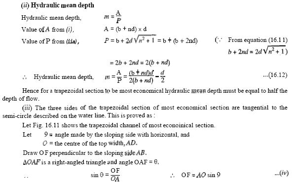
182


183 Thus, if a semi-circle is drawn with Q as centre and radius equal to the depth of flow d, the three sides of most economical trapezoidal section will be tangential to the semi-circle. Hence the conditions for the most economical trapezoidal section are: 3. A semi-circle drawn front 0 with radius equal to depth of flow will touch the three sides of the channel Problem: A trapezoidal channel has side slopes of 1 horizontal to 2 vertical and the slope of the bed is 1 in The area of the section is 40 m2. Find the dimensions of the section if it is most economical. Determine the discharge of the most-economical section if C = 50.


184 Problem: A trapezoidal channel has side slopes of 3 horizontal to 4 vertical and slope of its bed is 1.in Determine the optimum dimensions of the channel, if it is to carry water at 0.5 m 3 /s Take Chezy's constant as 80.
185 Flow through Circular Channel: The flow of a liquid through a circular pipe, when the level of liquid in the pipe is below the top of the pipe is classified as an open channel flow. The rate of flow through circular channel is determined from the depth of flow and angle subtended by the liquid surface at the centre of the circular channel.
186 Problem: Find the discharge through a circular pipe of diameter 3.0 m, if the depth of water in the pipe is 1.0 m and the pipe is laid at a slope of 1 h Take the value of Chery's constant as 70. Most Economical Circular Section: That for a most economical sections the discharge, for a constant cross-sectional area, slope of bed and resistance co-efficient, is maximum. But in case of circular channels, the area of flow cannot be maintained constant. With the change of depth of flow in a circular channel of any radius, the wetted area and wetted perimeter changes. Thus in case of circular channels, for most economical section, two separate conditions are obtained. They are:


187 1. Condition for maximum velocity, and sin Condition for maximum discharge. 1. Condition for Maximum Velocity for Circular Section. Fig show a circular channel through which water is flowing. Where A and P both are function of 0. The value of wetted area A is given by equation (16.17) as

188 where D = diameter of the circular channel. Thus for maximum velocity of flow, the depth of water in the circular channel should be equal to 0.81 Times the diameter of the channel Hydraulic mean depth for maximum velocity is Thus for maximum velocity, the hydraulic mean depth is equal to 0.3 times the diameter of circular channel.

189 2. Condition fur Maximum Discharge for Circular section. The discharge through a channel is given by

190 Where B = Diameter of the circular channel. Thus for maximum discharge through a circular channel the depth of flow is equal to 0.95 times its diameter. 3.7.Non-Uniform Flow Through Open Channels A flow is said to be uniform if the velocity of flow, depth of flow, slope of the bed of the channel and area of cross-section remain constant for a given length of the channel. On the other hand, if velocity of flow, depth of flow area of cross- section and slope of the bed of channel do not remain constant for a given length of pipe, the flow is said to be non-uniform. Non-uniform is further divided into Rapidly Varied Flow (R.V.F.) and gradually varied flow (G.V.F.) depending upon the change of depth of flow over the length of the channel If the depth of flow changes abruptly over a small length of the channel, the flow is said as rapidly varied flow. And if the depth of flow in a channel changes gradually over a long length of channel, the flow is said to be gradually varied flow. 3.8.Specific Energy and Specific Energy Curve The total energy of a flowing liquid per unit weight is given by, Where z = Height of the bottom of channel above datum, h = Depth of liquid, and V= Mean velocity of flow. If the channel bottom is taken as the datum as shown in Fig. 3.15, then the total energy per unit weight of liquid will be,

, the specific energy of a flowing liquid Equation (16.22) gives the variation of specific energy (E) with the depth of flow (h).")
191 The energy given by equation (16.21) is known as specific energy. Hence specific energy of a flowing liquid is defined as energy per unit weight of the liquid with respect to the bottom of the channel. Specific Energy Curve It is defined as the curve which shows the variation of specific energy with Depth of flow It is obtained as: From equation (16.21), the specific energy of a flowing liquid Equation (16.22) gives the variation of specific energy (E) with the depth of flow (h). Hence for a given discharge Q, for different values of depth of flow, the corresponding values of E may be obtained. Then a graph between specific energy (along X- X axis) and depth of flow, h (along Y-Y axis) may be plotted.
192 Fig. 3.16: Specific energy curve Critical Depth: Critical depth is defined as that depth of flow of water at which the specific energy is minimum This is denoted by 'h c '. In Fig. 3.16, curve ACB is a specific energy curve and point C corresponds to the minimum specific energy the depth of flow of water at C is known as critical depth. The mathematical expression for critical depth is obtained by differentiating the specific energy equation (16.22) with respect to, depth of flow and equating the same to zero. But when specific energy is minimum depth is critical and it is denoted by h c. Hence critical depth is
 as Minimum Specific Energy in items of Critical Depth: Specific energy equation is given by equation (16.")
193 Critical Velocity (V c ): The velocity of flow at the critical depth is known as critical velocity. It is denoted by V c. The mathematical expression for critical velocity is obtained from equation (16.23) as Minimum Specific Energy in items of Critical Depth: Specific energy equation is given by equation (16.22) When specific energy is minimum, depth of flow is critical depth and hence above equation becomes as
194 Problem: Find the specific energy of flowing water through a rectangular channel of width 5m when the discharge is 10m 3 /s and depth of water is 3 m. Problem: Find the critical depth and critical velocity of the water flowing through a rectangular channel of width 5m, when discharge is 15m3/s. Problem: The discharge of water through a rectangular channel of width 8m, is 15m 3 /s when depth of flow of water is 1.2 m. Calculate: (i) Specific energy of the flowing water, (ii) Critical depth and critical velocity, (iii) Value of minimum specific energy.
195 Critical Flow: It is defined as that flow at which the specific energy is minimum or the flow corresponding to critical depth is defined as critical flow. Equation (16.24) gives the relation for critical velocity in terms of critical depth as Streaming Flow or Sub-critical Flow or Tranquil Flow. When the depth of flow in a channel is greater than the critical depth (h e,), the flow is said to be sub-critical flow or streaming flow or tranquil flow. For this type of flow the Froude number is less than one i.e., F e < 1.0. Super-critical Flow or Shooting Flow or Torrential Flow: When the depth of flow in a channel is less than the critical depth (h e,), the flow is said to be super-critical flow or shooting flow or torrential flow. For this type of flow the Froude number is greater than one i.e., F e > 1.0. Alternate Depths: In the specific energy curve shown in Fig. 3.16, the point C corresponds to the minimum specific energy and the depth of flow at C is called critical depth. For any other value of the specific energy, there are two depths, one greater than the critical depth and other smaller than the critical depth. These two depths for a given specific energy are called the alternate depths. These depths are shown as h 1 and h 2 in Fig Or the depths conesp6nding to points G and H in Fig are called alternate depths. Condition for Maximum Discharge for a given value of Specific Energy:The specific energy (E) at any section of a channel is given by equation (16.21) as
196 3.9.Hydraulic Jump or Standing Wave Consider the flow of water over a dam as shown in Fig The height of water at the section 1-1 is small. As we move towards downstream, the height or depth of water increases rapidly over a short length of the channel. This is because at the section 1-1, the flow is a shooting flow as the depth of water at section Fig.3.17: Hydraulic Jump 1-1 is less than critical depth. Shooting flow is Un-unstable type of flow and does not continue on the downstream side. Then this shooting will convert itself into a streaming or tranquil flow and hence depth of water will increase. This sudden increase of depth of water is called a hydraulic jump or a standing wave. Thus hydraulic jump is defined as "The rise of water level, which takes place due to the transformation of the unstable shooting flow (Supercritical) to the stable streaming flow (sub-critical flow)." When hydraulic jump takes place, a loss of energy due to eddy formation and turbulence occurs. Expression for Depth of Hydraulic Jump: Before deriving an expression for the depth of Hydraulic jump, the following assumptions are made:
197 1. The flow is uniform and pressure distribution is due to hydrostatic before and after the jump. 2. Losses due to friction on the surface of the bed of the channel are small and hence neglected. 3. The slope of the bed of the channel is small, so that the component of the weight of the fluid in the direction of flow is negligibly small. Consider a hydraulic jump formed in a channel of horizontal bed as shown in Fig Consider two sections 1-1 and before and after hydraulic jump. Fig. 3.18: Hydraulic Jump Let d l = Depth of flow at section 1-1, d 2 = Depth of I-low at section 2-2, V l = Velocity of flow at section 1-1, V 2 = Velocity of flow at section 2-2, Z l = Depth of centroid of area at section 1-1 below free surface Z 2 = Depth of centroid of area at section 2-2 below free surface, A l = Area of cross-section at section 1-1, and A 2 = Area of cross-section at section 2-2. Consider unit width of the channel. The forces acting on the mass of water between sections 1-1 and 2-2 are (i) Pressure force, P1 on section 1-1, (ii) Pressure force, P2 on section 2-2, (iii) Frictional force on the floor of the channel, which assumed to be negligible.
198 Net force acting on the mass of water between sections 1-1 and 2-2 But from momentum principle, the net force acting on a mass of fluid must be equal to the rate of change of momentum in the same section. :. Rate of change of momentum in the direction of force = mass of water per sec x change of velocity in direction of force Now mass of water per second = p x discharge per unit width x width = p x q x 1 = pqm 3 /s Change of velocity in the direction of force = (V l - V 2 ) [as net force is acting from right to left, the change of velocity should be taken from right to left and Hence is equal to (V l - V 2 )] :. Rate of change of momentum in the direction of force = ρq (V l - V 2 )...(iii) Hence according to momentum principle, the expression given by equation (i) is equal to the expression given by equation (iii)
199 Expression for loss of Energy due to Hydraulic Jump as mentioned in earlier That when hydraulic jump takes place, a loss of energy due to eddies formation and turbulence occurs. This loss of energy is equal to the difference of specific energies at sections 1-1 and 2-2. Or loss of energy due to hydraulic jump, But from equation (vi)
200 Length of Hydraulic Jump: This is defined as the length between the two sections where one section is taken before the hydraulic jump and the second section is taken immediately after the jump. For a rectangular channel from experiments, it has been found equal to 5 to 7 times the height of the hydraulic jump. Problem: The depth of flow of water, at a certain section of a rectangular channel of 4 m wide, is 0.5m. This discharge through the channel is 16m 3 /s. If a hydraulic jump takes place on the downstream side, find the depth of flow after the jump.
201 3.10. Gradually Varied Flow (G.V.F) If the depth of flow in a channel changes gradually over a long length of the channel, the flow is said to be gradually varied flow and is denoted by G.V.F. Equation of Gradually Varied Flow: Before deriving an equation for gradually varied flow, the following assumption are made: 1. The bed slope of the channel is small, 2. The flow is steady and hence discharge Q is constant, 3. Accelerative effect is negligible and hence hydrostatic pressure distribution prevails over channel cross-section. 4. The energy correction factor, a is unity, 5. The roughness co-efficient is constant for the length of the channel and it does not depend on the depth of flow, 6. The formulae such as Chezy's formula, Manning's formula, which are applicable, to the uniform flow are also applicable to the gradually varied flow for determining the slope of energy line. 7. The channel is prismatic Consider a rectangular channel having gradually varied flow. The depth of flow is gradually decreasing in the direction of flow. Let Z = height of bottom of channel above datum h = depth of flow, V = mean velocity of flow, i b = slope of the channel bed, i e = slope of the energy line, b = width of channel, and Q = discharge through the channel.
202
203 This is also called the slope of the free water surface Thus: Problem: Find the rate of change of depth of water in a rectangular channel of 10rn wide and 1.5m deep, when the water is flowing with a velocity of 1m/s. The flow of water through the channel of bed slope 1 in 4000, is regulated in such way that energy line is having a slope of

204 Problem: Find the slope of the free water surface in a rectangular channel of width20 m, having depth of PO& 5 m. The discharge through the channel is 50 m3/s. The bed of the channel is having a slope of 1 in Take t h y l u e of Chezy 's constant, C = 60. Back: Water Curve and Affux. On the upstream side of the dam, the depth of water will be rising. If there had not been any obstruction (such as dam) in the path of flow of water in the channel, the depth of water would have been constant as shown by dotted line parallel to the bed of the channel in Fig Due to obstruction, the water level rises and it has maximum depth from the bed at some section.
205 Let h 1 = depth of water at the point, where the water starts rising up, and h 2 = maximum height of rising water from bed. Then (h 2 h 1 ) = Affux. Thus affux is defined as the maximum increase in water level due to obstruction in the path of flow of water. The profile of the rising water on the upstream side of the dam is called backwater curve. The distance along the bed of the channel between the section where water starts rising to the section where water is having maximum height is known as length of back water curve. Expression for the Length of Back Wader Curve: Consider the flow of water through a channel in which depth of water is rising. Let the two sections 1-1 and 2-2 are at such a distance that the distance between them represents the length 0f back water curve. Let h 1 = depth of flow at section 1-1, V 1 = velocity of flow at section 1-1, h 2 = depth of flow at section 2-2, Fig.3.20: Length of back water curve
206 Equation (16.34) is used to calculate the length of back water curve. 'The value of i e (slope of energy line) is calculated either by Manning's formula or by Chezy's formula. The mean values of velocity, depth of flow, hydraulic mean depth etc. are used between sections 1-1 and 2-2 for calculating the value of i e Problem: Determine the length of the back water curve caused by an affux: of 2.0m in a rectangular channel of width 40m and depth 2.5m. The slope of the bed is given as 1 in Take Manning's N =.03.

207
208 3.11. Summary In this unit we have studied Classification of Flow in Channels Discharge through Open Channel by Chezy s Formula Empirical Formulae for the Value of Chezy s Constant Most Economical Section of Channels Non-Uniform Flow Through Open Channels Specific Energy and Specific Energy Curve Hydraulic Jump or Standing Wave Gradually Varied Flow (G.V.F) Keywords Uniform flow Steady flow Unsteady flow Laminar flow Turbulent flow Open Channels Energy Curve Gradually Varied Flow Hydraulic Jump Exercise 1. What do you understand by 'Flow in open channel? 2. Differentiate between: (i) Uniform flow and non-uniform flow, (ii) Steady and unsteady flow, (iii) Laminar and turbulent flow and (iv) Critical, sublgitica1 and super-critical flow in a open channel. 3. Explain the terms (i) Rapidly varied flow and (ii) Gradually varied flow. 4. Derive an expression for the discharge through a channel by Chezy's formula. 5. Explain the term: (i) Slope of the bed, (ii) Hydraulic mean depth and (iii) Wetted perimeter. 6. (a) What are the empirical formulae for determining the value of Chezy's constant? (b) What is the relation between Manning's constant and Chezy's constant.
209 7. State the following formulae for the values of C:- (I) Bazin's formulae, (ii) Kutter's formula and (iii) Manfling's formula. 8. (a) Define the term most economical section of a channel. What are the conditions for the rectangular channel of the best section? (b) What is meant by an economical section of a channel? 9. Prove that for the trapezoidal channel of most economical section : (i) Half of top width = Length of one of the slopping sides (ii) Hydraulic mean depth = 15 depth of flow. 10. (a) Derive the condition for the best side slope of the most economical trapezoidal channel. (b) Find the side slope in a trapezoidal section of maximum efficiency which will carry the same flow as a half square section of the same area. 11. Prove that for a channel of circular section, the depth of flow, d = 0.81 D for maximum velocity, and = 0.95 D for maximum discharge, Where D = Diameter of circular channel, d = depth of flow. 12. Explain the terms: Specific energy of a flowing liquid, minimum specific energy, critical depth, critical velocity and alternate depths as applied to non-uniform flow. 13. What is specific energy curve? Draw specific energy curve, and then derive expressions for critical depth and critical velocity. 14. (a) Derive an expression for critical depth and critical velocity. (b) Define critical depth in an open channel in as many ways as you can. 15. Derive the condition for maximum discharge for a given value of specific energy. 16. Explain the term hydraulic jump. Derive an expression for the depth of hydraulic jump in terms of the upstream Froude number. 17. Derive an expression for the variation of depth along the length of the bed of the channel for gradually varied flow in an open channel. State clearly all the assumptions made. 18. Find an expression for loss of energy head for a hydraulic jump. Numerical Problems 1. Find the velocity of flow and rate of flow of water through a rectangular channel of 5 m wide and 2 m deep, when it is running full. The channel is having bed slope of 1 in Take Chezy's constant C = A flow of water of 150 liters per second flows down in a rectangular flume of width 70 cm and having adjustable bottom slope. If Chezy's constant C is 60, find the bottom slope necessary for uniform flow with a depth of flow of 40 cm. Also find the conveyance K of the flume.
210 3. Find the discharge through a trapezoidal channel of width 6 m and side slope of 1 horizontal to 3 vertical. The depth of flow of water is 3 m and Chezy's constant, C = 60. The slope of the bed of the channel is given 1 in SOW. 4. Find the rate of flow of water through a V-shaped channel having total angle between the sides as 60". Take the value of C = 50 and slope of h e bed 1 in The depth of flow is 6 m. 5. Find the discharge through a rectangular channel 3 m wide, having depth of water 2 m and bed slope as 1 in Take the value of K = 2.36 in Bazin's formula. 6. Find the discharge through the rectangular channel given in the above question, taking the value of N = in Manning's form? 7. Find the bed slo e of trapezoidal channel of bed width 3 m, depth of watet 2.5 m and side slope of 2 horizontal to 3 vertical, when the discharge through the channel is 16 m3/s. Taking the value of N = 0.03 in Manning's formula 8. Find the diameter of a circular sewer pipe which is laid at a slope of 1 in 1OOOO and carries a discharge of 1000 liters/s when flowing half full. Take the value of Manning's N = A rectangular channel carries water at the rate of 500 liters/s when bed slope is 1 is Find the most economical dimensions of the channel if C = A trapezoidal channel has side slopes of 1 horizontal to 2 vertical and the slope of the bed is 1 in The area of the section is 42 m2. Find the dimensions of the section if it is most economical. Determine the discharge of the most economical section if C = A trapezoidal channel with side slopes of 1 to 1 has to be designed to convey 9 m3/s at a velocity of 1.5 m/s so that the amount of concrete lining for the bed and sides is the minimum. Calculate the area of lining required for one meter length of canal. 12. A power canal of trapezoidal section has to be excavated through hard clay at the least cost. Determine the dimensions of the channel given, discharge equal to 15 m3/s, bed slope 1 : 2000 and Manning's,N = Find the discharge through a circular pipe of diameter 4.0 m, if the depth of water in the pipe is 1.33 m and pipe is laid at a slope of 1 in Take the value of Chezy's constant = Water is flowing through a circular channel at the rate of 5d0 liters/s. The depth of water in the channel is 0.7 times the diameter and the slope of the bed of the channel is 1 in Find the diameters of the circular channel if the value of Manning's, N =.015.
211 15. The rate of flow of water through a circular channel of diameter 0.8 m is 200 liters/s. Find the slope of the bed of the channel for maximum velocity. Take C = Determine the maximum discharge of water through a circular channel of diameter 2.0 m when the bed slope of the channel is 1 in Take C = The discharge of water through a rectangular channel of width 6 m, is 18 m3/s when depth of flow of water is 2 m. Calculate: (9 specific energy of the flowing water, (iq critical depth and critical velocity and (ii9 value of minimum specific energy. 18. The specific energy for a 6 m wide rectangular channel is to be 5 kg-m/kg. If the rate of flow of water through the channel is 24 m2/s determine the alternate depths of flow.
212 Unit 4 VISCOUS FLOW Structure 4.1.Introduction 4.2.Objectives 4.3.Flow of Viscous Fluid through Circular Pipe 4.4.Flow of Viscous Fluid between two Parallel Plates 4.5.Kinetic Energy Correction and Momentum Correction Factors 4.6.Power Absorbed in Viscous Flow 4.7.Loss of Head Due to Friction in Viscosity Flow 4.8.Movement of Piston in Dash-Pot 4.9.Methods of Determination of Coefficient of Viscosity Summary Keywords Exercise 4.1.Introduction This chapter deals with the flow of fluids which are viscous and flowing at very low velocity. At low velocity the fluid moves in layers. Each layer of fluid slides over the adjacent layer. Due to relative velocity between two layers the velocity gradient du/dy exists and hence a shear stress t = µ du/dy acts on the layers. 'The following cases will be considered' in this chapter: 1. Flow of viscous fluid through circular pipe. 2. Flow of viscous fluid between two parallel plates. 3. Kinetic Energy correction and momentum correction factors. 4. Power absorbed in viscous flow through (a) Journal Bearings, (b) Foot-step Bearings, and (c) Collar Bearings.
213 4.2.Objectives After studying this unit we have studied Flow of Viscous Fluid through Circular Pipe Flow of Viscous Fluid between two Parallel Plates Kinetic Energy Correction and Momentum Correction Factors Power Absorbed in Viscous Flow Loss of Head Due to Friction in Viscosity Flow Movement of Piston in Dash-Pot Methods of Determination of Coefficient of Viscosity 4.3.Flow of Viscous Fluid through Circular Pipe For the flow of viscous fluid through circular pipe, the velocity distribution across a section, the ratio of maximum velocity to average velocity, the shear stress distribution and drop of pressure for a given length is to be determined. The flow through the circular pipe will be viscous or laminar, if the Reynolds number (Re*) is less than The expression for Reynold number is given by Where p = Density of fluid flowing through pipe, V = Average velocity of fluid, D= Diameter of pipe and p = Viscosity of fluid. Fig.4.1: Viscous flow through a pipe Consider a horizontal pipe of radius R. The viscous fluid is flowing from left to right in the pipe as shown in Fig. 4.1 (a). Consider a fluid element of radius r, sliding in a cylindrical fluid element of radius (r + dr).

214 Let the length of fluid element be Ax. If 'p' is the intensity of pressure on the face AB, then the intensity of pressure on face CD will be p + - Ax. Then the forces acting on the fluid element are: 3. the sheer force, t x 2πr x on the surface of fluid element. As there is no acceleration, hence the summation of all forces in the direction of flow must be zero i.e. The shear stress t across a section varies with 'r' as dp/dx across a section is constant. Hence shear stress distribution across a section is linear as shown in Fig. 4.2 (2). Fig.4.2: Shear stress and velocity distribution across a section
 across the section is obtained by considering the flow through a circular ring element of radius r and thickness dr as shown in Fig. 4.1 (b).")
215 The average velocity, U, is obtained by dividing the discharge of the fluid acmss the section by the area of the pipe (πr 2 ). The discharge (Q) across the section is obtained by considering the flow through a circular ring element of radius r and thickness dr as shown in Fig. 4.1 (b). The fluid flowing per second through this elementary ring
216 Problem: A crude oil of viscosity 0.97poise and relative density 0.9 is flowing through a horizontal circular pipe of diameter 100mm and of length 10 m. Calculate the difference of pressure at the two ends of the pipe, if 100kg of the oil is collected in a tank in 30 seconds.

217 For laminar or viscous flow, the Reynolds number (Re) is less than Let us calculate the-reynolds number for this problem. Problem: An oil of viscosity 0.1Ns/m 2 and relative density 0.9 is flowing through a circular pipe of diameter 50 mm and of length 300 m. The rate of flow of fluid through the pipe is 3.5 liters/s. Find the pressure drop in a length of 300 m and also the shear stress at the pipe wall.
218 Problem: A laminar flow is taking place in a pipe of diameter of 200 mm. The maximum velocity is 1.5m/s. Find the mean velocity and the radius at which this occurs. Also calculate the velocity at 4cm from the wall of the pipe.
219 Problem: Crude oil of µ = 1.5poise and relative density 0.9 flows through a 20 mm diameter vertical pipe. The pressure gauges fixed 20 m apart read N/cm 2 and N/cm 2 as shown in Fig Find the direction and rate of flow through the pipe.
220
 the pressure gradient (b) the average velocity and (c) Reynold number of the flow.")
221 Problem: A fluid of viscosity 0.7N/m 2 and specific gravity 1.3 is flowing through a circular pipe of diameter 100 mm. The maximum shear stress at the pipe wall is given as N/m 2 find (a) the pressure gradient (b) the average velocity and (c) Reynold number of the flow. Problem: What power is required per kilometer of a line to overcome the viscous resistance to the flow of glycerin through a horizontal pipe of diameter 100 mm at the rate of 10 liters/s? Take p = 8 poise and kinematic viscosity (v) = 6.0 stokes.

222 4.4.Flow of Viscous Fluid between two Parallel Plates In this case also, the shear stress distribution, the velocity distribution across a section; the ratio of maximum velocity to average velocity and difference of pressure head for a given length of parallel plates, are to be calculated. Fig.4.6: viscous flow between two parallel plates
223 For steady and uniform flow, there is no acceleration and hence the resultant force in the direction of flow is zero. (I) Velocity Distribution TO obtain the velocity distribution across a section, the value of shear stress t = µ(du/dy) from Newton's law of viscosity for laminar flow is substituted in equation (9.6). Integrating the above equation w.r.t. y, we get Where C 1 and C 2 are constants of integrations Their values are obtained from the two boundary conditions that is (i) at y=o, u=o (ii) at y=t, u=o In the above equation, µ, dp/ax and t are constant. It means u varies with the Square of y. Hence equation ax (9.9) is an equation of a parabola. Hence velocity distribution across a section of the parallel plate is parabolic. This velocity distribution is shown in Fig. 4.7(a).
224 Fig.4.7: Velocity distribution and shear stress distribution across a section of parallel plates (ii) Ratio of Maximum Velocity to Average Velocity. The velocity is maximum when y = t/2. Substituting this value in equation (9.9), we get The average velocity, U, is obtained by dividing the discharge (Q) across the section by the area of the section (t x 1). And the discharge Q is obtained by considering the rate of flow of fluid through the strip of thickness dy and integrating it. The rate of flow through strip is (iii) Drop of Pressure head for a given Length. From equation (9.11), we have Integrating this equation w.r.t x, we get
 into Problem: Calculate : (a) the pressure gradient along flow, (b) the average")

225 (iv) Shear Stress Distribution it is obtained by substituting the value of u from equation (9.9) into Problem: Calculate : (a) the pressure gradient along flow, (b) the average velocity, and (c) the discharge for an oil of viscosity 0.02 N/m 2 flowing between two stationary parallel plates 1m wide maintained 10mm apart. The velocity midway between the plates is 2m/s.

226 Problem: Determine (a) the pressure gradient, (b) the shear stress at the two horizontal parallel plates and (c) the discharge per meter width for the laminar flow of oil with a maximum velocity of 2m/s between two horizontal parallel fired plates which are 100 mm apart. Given p = N/m 2. Problem: An oil of viscosity 10poise flows between two parallel fixed plates which are kept at a distance of 50mm apart. Find the rate of flow of oil between the plates if the drop of pressure in a length of 1.2m be 0.3N/cm 3. The width of the plates is 200 mm.
227 Problem: Water at 15 Cflows between two large parallel plates at a distance of 1.6 mm apart Determine (a) the maximum velocity (b) the pressure dropper unit length and (c) the shear stress at the walls of the plates if the average velocity is 0.2m/s. The viscosity of water at 15 C is given as 0.01 poke 4.5.Kinetic Energy Correction and Momentum Correction Factors Kinetic Energy correction factor is defined as the ratio of the kinetic energy of the flow per second based on actual velocity across a section to the kinetic energy of the flow per second based on average velocity across the same section. It is denoted by a. Hence mathematically, Momentum Correction Factor It is defined as the ratio of momentum of the flow per second based on actual velocity to the momentum of the flow per second based on average velocity across a section. It is denoted by β. Hence mathematically
228 Problem: Show that the momentum correction factor and energy correction factor for laminar flow through a circular pipe are 4/3 and 2.0 respectively. Sol. (i) Momentum Correction Factor or β The velocity distribution through a circular pipe for laminar flow at any radius r is given by equation (9.3) Consider an elementary area da in the form of a ring at a radius r and of width dr, then Fig.4.9 Rate of fluid flowing through the ring = dq = velocity x area of ring element = u x b r d r Momentum of the fluid through ring per second = mass x velocity = p x dq x u = ρ x 2πrdr x u x u = 2πρu 2 rdr Therefore total actual momentum of the fluid per second across the section Substituting the value of u from (I),

229

230 Total actual kinetic energy of flow per second 4.6.Power Absorbed in Viscous Flow For the lubrication of the machine parts, oil is used. Flow of oil is bearings are an example of viscous flow. If highly viscous oil is used for lubrication of bearings, it will offer great resistance and thus a greater I power loss will take place. But if light oil is used, a required film between the rotating part and stationary I metal surface will not be possible. Hence, the
231 wear of the two surfaces will take place. Hence an.oil of correct viscosity should be used for 1ubrication the power required to overcome the viscous resistance in the following cases will be determined: 1. Viscous resistance of Journal Bearings, 2. Viscous resistance of Foot-step Bearings, 3. Viscous resistance of Collar Bearings. Viscous Resistance of Journal Bearings Consider a shaft of diameter D rotating in a journal bearing. The clearance between the shaft and journal bearing is filled with viscous oil. The oil film in contact with the shaft rotates as the same speed as that of shaft while the oil film in contact with journal bearing is stationary. Thus the viscous resistance will be offered by the oil to the rotating shaft. Let N = speed of shaft in r.p.m. t = thickness of oil film L = length of oil film As the thickness of oil film is very small, the velocity distribution in the oil film can be assumed as linear.

232 Therefore Torque required overcoming the viscous resistance, Therefore power absorbed in overcoming the viscous resistance Problem: A shaft having a diameter of 50 mm rotates centrally in a journal bearing having a diameter of mm and length 100 mm. The angular space between the shaft and the bearing is filled with oil having viscosity of 0.9poise. Determine the power absorbed in the bearing when the speed of rotation is 60 r.p.m. Problem: A shaft of 100 mm, diameter rotates at 60 r.p.m. in a 200 mm long bearing. Taking that the two surfaces are uniformly separated by a distance of 0.5 mm and taking linear velocity distribution in the lubricating oil having dynamic viscosity of 4 centipoises, find the power absorbed in the bearing.

233 Problem: A shaft of diameter 0.35 m rotates at 200 r.p.m. inside a sleeve 100 mm long. The dynamic viscosity of lubricating oil in the2 mm gap between sleeve and shaft is 8poises Calculate the power lost in the bearing. Problem: A sleeve, in which a shaft of diameter 75 mm, is running at 1200 r.p.m., is having a radial clearance of 0.1 mm. Calculate the torque resistance if the length of sleeve is 100 mm and the space is filled with oil of dynamic viscosity 0.96poise.

234 Viscous Resistance of Foot-Step Bearing: Fig shows the foot-step bearing, in which a vertical shaft is rotating. An oil film between the bottom surface of the shaft and bearing is provided, to reduce the wear and tear. The viscous resistance is offered by the oil to the shaft. In this case the radius of the surface of the shaft in contact with oil is not constant as in the case of the journal bearing. Hence, viscous resistance in foot-step bearing is calculated by considering an elementary circular ring of radius r and thickness dr as shown in Fig Fig.4.11: Foot-step bearing Let N = speed of the shaft t = thickness of oil film R = radius of the shaft Area of the elementary ring = 2πrdr Now shear stress is given by Where Vis the tangential velocity of shaft at radius r and is equal to Therefore Shear force on the ring = df = t x area of elementary ring Torque required overcoming the viscous resistance,

235 Total torque required to overcome the viscous resistance, Problem: Find the torque required to rotate a vertical shaft of diameter 100 mm at 750 r.p.m. The lower end of the shaft rests in a foot-step bearing. The end of the shaft and surface of the hearing are both flat and are separated by an oil film of thickness 0.5 mm. The viscosity of the oil is given 1.5poise. Problem: Find the power required to rotate a circular disc of diameter 200 mm at 1000 r.p.m. The circular disc has a clearance of 0.4mm from the bottom flat plate and the clearance contains oil of viscosity 1.05 poise. Thickness of oil film, t = 0.4 mm = m
236 The power required to rotate the disc is given by equation (9.20) or Viscous Resistance of Collar Bearing Fig shows the collar bearing, where the face of the collar is separated from bearing surface by an oil film of uniform thickness. Let N = Speed of the shaft in r.p.m. R 1 = Internal radius of the collar R 2 = Eaernal radius of the collar t = Thickness of oil film. Fig.4.12: Collar bearing Consider an elementary circular ring of radius 'r' and width dr of the bearing surface. Then the torque (62") required to overcome the viscous resistance on the elementary circular ring is the same as given by equation (9.19A) or Therefore total torque, required to overcome the viscous resistance, on the whole collar is Power absorbed in overcoming viscous resistance Problem: A collar bearing having external and internal diameters 150 mm and 100 mm respectively is used to take the thrust of a shift. An oil film of thickness 0.25 mm is maintained between the collar surface and the bearing. Find the power lost in overcoming the viscous resistance when the shaft rotates at 300 r.p.m. Take p = 0.91 poise.
237 Problem: The external and internal diameters of a collar bearing are 200 mm and 150 mm respectively. Between the collar surface and the bearing, an oil film of thickness 0.25 mm and of viscosity 0.9poise, is maintained. Find the torque and the power lost in overcoming the viscous resistance of the oil when the shaft is running at 250 r.p.m.
 is Problem: Water is flowing through a 200mm diameter pipe with coefficient of friction f=0.04 the sheer stress at a point 40mm from the pipe axis is 0.")
238 4.7.Loss of Head Due to Friction in Viscosity Flow The loss of pressure head, h f in a pipe of diameter D 1 in which a viscous fluid of viscosity µ is flowing with a velocity is given by Hagen Poiseuille formula i.e. by equation (9.6) is Problem: Water is flowing through a 200mm diameter pipe with coefficient of friction f=0.04 the sheer stress at a point 40mm from the pipe axis is N/cm 2. Calculate the shear stress at the pipe wall.

239 Problem: A pipe of diameter 20 cm and length 10' m is laid at a slope of1 in 200. An oil of sp. gr. 0.9 and viscosity 1.5poke is pumped up at the rate of 20 liters per second. Find the head lost due to friction. Also calculate the power required to pump the oil. As the Reynold number is less than 2000, the flow is viscous. The co-efficient of friction for viscous flow is given by equation (9.23) as Due to slope of pipe 1 in 200, the height through which oil is to be raised by pump = Slope x Length of pipe


240 4.8.Movement of Piston in Dash-Pot V is the velocity of piston or the velocity of oil in dash-pot in contact with piston. The rate of flow of oil in dash-pot Rate of flow through clearance = velocity through clearance x area of clearance = u x d3 x t Due to continuity equation, rate of flow through clearance must be equal to rate of flow through dash-pot.
241 Problem: An oil dash-pot consists of a piston moving in a cylinder having oil. This arrangement is used to damp out the vibrations. The piston falls with uniform speed and covers 5cm in 100 seconds. If an additional weight of 1.36 N is placed on the top of the piston it falls through 5 cm in 86 seconds with uniform speed the diameter of the piston is 7.5 cm and its length is I0 cm. The clearance between the piston and the cylinder is 0.12 cm which is uniform throughout. Find the viscosity of oil.
242 4.9.Methods of Determination of Coefficient of Viscosity The following are the experimental methods of determining the co-efficient of viscosity of a liquid: 1. Capillary tube method, 2. Falling Sphere resistance method, 3. By Rotating cylinder method, and 4. Orifice Type Viscometer. The apparatus used for determining the viscosity of a liquid is called viscometer. Capillary Tube Method: In capillary tube method, the viscosity of a liquid is calculated by measuring the pressure difference for a given length of the capillary tube. The Hagen Poiseuille law is used for calculating viscosity. Fig.4.14: Capillary tube viscometer Fig shows the capillary tube viscometer. The liquid whose viscosity is to be determined is filled in a constant head tank. The liquid is maintained at constant temperature and is allowed to pass through the capillary tube from the constant head tank. Then, the liquid is collected in a measuring tank for a given time. Then the rate of liquid collected in the tank per second is determined. The pressure head 'h' is measured at a point far away from the tank as shown in Fig Then h = Difference of pressure head for length L. The pressure at outlet is atmospheric,

243 Let D = Diameter of capillary tube, L = Length of tube for which difference of pressure head is known, p = Density of fluid, µ = Coefficient of viscosity. Falling Sphere Resistance Method Theory: This method is based on Stoke's law, according to which the drag force, F on a small sphere moving with a constant velocity, U through a viscous fluid of viscosity. µ for viscous conditions is given by Fig.4.15: Falling sphere resistance method When the sphere attains a constant velocity U, the drag force is the difference of between the weight of sphere and buoyant force acting on it.
244 Hence in equation (9,26), the values of d, U, p, and ρf are known and hence the viscosity of liquid can be determined. Method: Thus this method consists of a tall vertical transparent cylindrical tank, which is filled with the liquid whose viscosity is to be determined. This tank is surrounded by another transparent tank to keep the temperature of the liquid in the cylindrical tank to be constant. A spherical ball of small diameter d is placed on the surface of liquid. Provision is made to release the drop this ball. After a short distance of travel, the ball attains a constant velocity. The time to travel a known vertical distance between two fixed marks on the cylindrical tank is noted to calculate the constant velocity U of the ball. Then with the known values of d, p, pf the viscosity y of the fluid is calculated by using equation (9.26). Rotating Cylinder Method This method consists of two concentric cylinders of radii R 1 and R 2 as shown in Fig The narrow space between the two cylinders is filled with the liquid whose viscosity is to be determined. The inner cylinder is held stationary by means of a tensional spring while outer cylinder is rotated at constant angular speed w. The torque T acting on the inner cylinder is measured by the torque on the inner cylinder must be equal and opposite to the torque applied on the outer cylinder.

245 Fig.4.16: Rotating cylinder viscometer The torque applied on the outer cylinder is due to viscous viscous resistance provided by liquid in the annular space and at the bottom of the inner cylinder. Tangential velocity of liquid layer in contact with outer cylinder will be equal to the tangential velocity of outer cylinder. Velocity of liquid layer with outer cylinder = ω x R 2 Velocity of liquid layer with inner cylinder = 0 Velocity gradient over the radial distance (R2 - R1) The torque T I on the inner cylinder due to shearing action of the liquid in the annular space is If the gap between the bottom of the two cylinders is 'h', then the torque applied on inner cylinder (T 2 ) is given by equation (9.19) as
.")
246 Where T = torque measured by the strain of the torsional spring, R 1, R 2 = radii of inner and outer cylinder, h = clearance at the bottom of cylinders, H = height of liquid in annular space, µ = co-efficient of viscosity to be determined. Hence the value of p can be calculated from equation (9.27). Orifice Type Vbcometer In this method, the time taken by a certain quantity of the liquid whose viscosity is to be determined, to flow through a short capillary tube is noted down. The co-efficient of viscosity is then obtained by comparing with the co-efficient of viscosity of a liquid whose viscosity is known or by the use conversion factors. Viscometers such as Saybolt, Red wood or Engler are usually used. The principle for all the three viscometer is same. In the United Kingdom Redwood viscometer is used while in U.S.A.;Saybolt viscometer is commonly used. Fig shows that Saybolt viscometer, which consists of a tank at the bottom of which a short capillary tube is fitted. In this tank the liquid whose viscosity is to be determined is filled. This tank is surrounded by another tank, called constant temperature bath. The liquid is allowed to flow through capillary tube at a standard temperature. The time taken by 60 C.C. of the liquid to flow through the capillary tube is noted down. The initial height of liquid in the tank is previously adjusted to a standard height. From the time measurement, the kinematic viscosity of liquid is known from the relation, Where A = 0.24, B = 190, t =time noted in seconds, v = kinematic viscosity in stokes.

247 Fig.4.17: Saybolt viscometer Problem: The viscosity of an oil of sp. gr. 0.9 is measured by a capillary tube of diameter 50 mm. The difference of pressure head between two points 2 m apart is 0.5 m of water. The mass of oil collected in a measuring tank is 60 kg in 100 seconds. Find the viscosity of oil. Problem: A capillary tube of diameter 2 mm and length 100 mm is used for measuring viscosity of a liquid. The difference of pressure between the two ends of the tube is N/cm2 and the viscosity of liquid is 0.25poke. Find the rate of flow of liquid through the tube.

248 Problem: A sphere of diameter 2 mm falls 150 mm in 20 seconds in a viscous liquid. The density of the sphere is 7500 kg/m3 and of liquid is 900 kg/m3. And the co-efficient of viscosity of the liquid Summary In this unit we have studied Flow of Viscous Fluid through Circular Pipe Flow of Viscous Fluid between two Parallel Plates Kinetic Energy Correction and Momentum Correction Factors Power Absorbed in Viscous Flow Loss of Head Due to Friction in Viscosity Flow
249 Movement of Piston in Dash-Pot Methods of Determination of Coefficient of Viscosity Keywords Viscous Fluid Circular Pipe Parallel Plates Kinetic Energy Friction Piston Exercise

250
251 Unit 1 WATER WHEELS Structure 1.1. Introduction 1.2. Objectives 1.3. Turbines 1.4. General Layout of a Hydro-Electrical Power Plant 1.5. Definitions of Heads and Efficiencies of a Turbine 1.6. Classification of Hydraulic Turbines 1.7. Pelton Wheel (or Turbine) 1.8. Velocity Triangles and Work done for Pelton Wheel 1.9. Summary Keywords Exercise 1.1. Introduction Hydraulic machines are defined as those machines which convert either hydraulic energy (energy possessed by water) into mechanical energy (which is further converted into electrical energy) or mechanical energy into hydraulic energy. The hydraulic machines, which convert the hydraulic energy into Mechanical energy, are called turbines while the hydraulic machines which convert the mechanical energy into hydraulic energy are called pumps. Thus the study of hydraulic machines consists of study of turbines and pumps Turbines consists of mainly study of Pelton turbine, Francis Turbine and Kaplan Turbine while pumps consist of study of centrifugal pump and reciprocating pumps Objectives After studying this unit we are able to understand Turbines General Layout of a Hydro-Electrical Power Plant Definitions of Heads and Efficiencies of a Turbine Classification of Hydraulic Turbines Pelton Wheel (or Turbine) Velocity Triangles and Work done for Pelton Wheel
252 1.3. Turbines Turbines are defined as the hydraulic machines which convert hydraulic energy into mechanical energy. This mechanical energy is used in running an electric generator which is directly coupled to the shaft of the turbine. Thus the mechanical energy is convert electrical energy. The electric power which is obtained from the hydraulic energy (energy of water) is known as Hydro-electric power. At present the generation of hydro-electric power is the cheapest as compared by the power generated by other sources such as oil, coal etc General Layout of a Hydro-Electrical Power Plant Fig. 1.1 shows a general lay-out of a hydro-electric power plant which consists of : (i) A dam constructed across a river to store water. (ii) Pipes of large diameters called penstocks, which carry water under pressure from the storage reservoir to the turbines. These pipes are made of steel or reinforced concrete. (iii) Turbines having different types of vanes fitted to the wheels. (iv) Tail race, which is a channel which carries water away from the turbines after the water has worked on the turbines. The surface of water in the tail race is also known as tail race Definitions of Heads and Efficiencies of a Turbine 1. Gross Head. The difference between the head race level and tail race level when no water is flowing is known as Gross Head. It is denoted by 'H,' in Fig Net Head. It is also called effective head and is defined as the head available at the inlet of the turbine. When water is flowing from head race to the turbine, a loss of head due to friction between the water and penstocks occurs. Though there are other losses also such as loss due to bend, pipe fittings, loss at the entrance of penstock etc., yet they are having all small magnitude as compared to head loss due to friction between penstocks and water than net heat on turbine is give by..(1.1
 Hydraulic Efficiency, η h (b) Mechanical Efficiency, η m, (c) Volumetric Efficiency, η v and (d) Overall Efficiency, η θ (a) Hydraulic Efficiency (η h ).")
253 Fig.1.1: Layout of a Hydro-electric Power Plant 3. Efficiencies of a Turbine. The followings are the important efficiencies of a turbine. (a) Hydraulic Efficiency, η h (b) Mechanical Efficiency, η m, (c) Volumetric Efficiency, η v and (d) Overall Efficiency, η θ (a) Hydraulic Efficiency (η h ). It is defined as the ratio of power given by water to the runner of a turbine (runner is a rotating pan of a turbine and on the runner vanes are fixed) to the power supplied by the water at the inlet of the turbine. The power at Be inlet of the turbine is more and this power goes on decreasing as the water flows over the vanes of the turbine due to hydraulic losses as the vanes are not smooth. Hence the power delivered to the runner of the turbine will be less-than the power available at the inlet of the turbine. Thus, mathematically, the hydraulic efficiency of a turbine is written as

 to the power delivered to the runner is defined as mechanical efficiency. Hence, mathematically, it is written as.")
254 The relation (1.2 B) is only used when the flowing fluid is water. If the flowing fluid is other than the water, then relation (1.2 A) is used. (b) Mechanical Efficiency (η m ). The power delivered by water to the runner of a turbine is transmitted to the shaft of the turbine. Due to mechanical losses, the power available at the shaft of the turbine is less than the power delivered to the runner of a turbine. The ratio of the power available at the shaft of the turbine (known as S.P. or B.P.) to the power delivered to the runner is defined as mechanical efficiency. Hence, mathematically, it is written as..(1.3) (c) Volumetric Efficiency (q,). The volume of the water striking the runner of a turbine is slightly less than the volume of the water supplied to the turbine. Some of the volume of the water is discharged to the tail race without striking the runner of the turbine. Thus the ratio of the volume of the water actually striking the runner to the volume of water supplied to the turbine is defined as volumetric efficiency. It is written as (1.4) (6) Overall Efficiency (η o ). It is defined as the ratio of power available at the shaft of the turbine to the power supplied by the water at the inlet of the turbine. It is written as:
255 Where P = Shaft Power...(1.6) 1.6. Classification of Hydraulic Turbines The hydraulic turbines are classified according to the type of energy available at the inlet of the turbine, direction of flow through the vanes, head at the inlet of the turbine and specific speed of the turbines. Thus the followings are the important classification of the turbines: If at the inlet of the turbine, the energy available is only kinetic energy, the turbine is known as impulse turbine. As the water flows over the vanes, the pressure is atmospheric from inlet to outlet of the turbine. If at the inlet of the turbine, the water possesses kinetic energy as well as pressure energy, the turbine is known as reaction turbine. As the water flows through the runner, the water is under pressure and the pressure energy goes on changing into kinetic energy. The runner is completely enclosed in an air-tight casing and the runner and casing is completely full of water. If the water flows along the tangent of the runner, the turbine is known at tangential flow turbine. If the water flows in the radial direction through the runner, the turbine is called radial flow turbine. If the water flows from outwards to inwards, radially, the turbine is Known as inward radial flow turbine, on the other hand, if water flows radially from inwards to outwards, the turbine is known as outward radial flow turbine. If the water flow through the runner along the direction parallel to the axis of rotation of the runner, the turbine is called axial flow turbine. If the water flows through the runner in the radial direction but
256 leaves in the direction parallel to the axis of rotation of the runner, the turbine is called mixed flow turbine Pelton Wheel (or Turbine) The Pelton wheel or Pelton turbine is a tangential flow impulse turbine. The water strikes the bucket along the tangent of the runner. The energy available at the inlet of the turbine is only kinetic energy. The pressure at the inlet and outlet of the turbine is atmosphere. This turbine is used for high heads and is named after L.A. Pelton, an American Engineer. Fig. 1.1 shows the lay-out of hydro-electric power plant in which the turbines Pelton wheel. The water from the reservoir flows through the penstocks at the outlet of which a nozzle is fitted. The nozzle increases the kinetic energy of the water flowing through the penstock. At the outlet of the nozzle, the water comes out in the form of a jet and strikes the buckets (vanes) of the runner. The main parts of the Pelton turbine are: 1. Nozzle and flow regulating arrangement (spear) 2. Runner and buckets 3. casing 4. Breaking jet. 1. Nozzle and Flow Regulating Arrangement. The amount of water striking the buckets (vanes) of the runner is controlled by providing n spear in the nozzle as shown in Fig The spear is a conical needle which is operated either by a hand wheel or automatically in an axial direction depending upon the size of the unit. When the spear is pushed forward into the nozzle the amount of water striking the runner is reduced. On the other hand, if the spear is pushed back, the amount of water striking the runner increases. Fig.1.2: Nozzle with a spear to regulate flow 2. Runner with Buckets. Fig. 1.3 shows the runner of a Pelton wheel. It consists of a circular disc on the periphery of which a number of buckets evenly spaced are fixed. The shape of the buckets is of a double hemispherical cup or bowl. Each bucket is divided into two symmetrical parts by a dividing wall which is known as splitter.
257 Fig.1.3: Runner of a pelton wheel The jet of water strikes on the splitter. The splitter divides the jet into two equal parts and the jet comes out at the outer edge of the bucket. The buckets are shaped in such a way that the jet gets deflected through 160" or 170". The buckets are made of cast iron, cast steel bronze or stainless steel depending upon the head at the inlet of the turbine. 3. Casing. Fig. 1.4 shows a Pelton turbine with a casing. The function of the casing is to prevent the splashing of the water and to discharge water to tail race. It also acts as a safeguard against accidents. It is made of cast iron or fabricated steel plates. The casing of the Pelton wheel does not perform any hydraulic function. Fig.1.4: Pelton Turbine
258 4. Breaking Jet. When the nozzle is completely closed by moving the spear in the forward direction, the amount of water striking the runner reduces to zero. But the runner due to inertia goes on revolving for a long time. To stop the runner in a short time, a small nozzle is provided which directs the jet of water on the back of the vanes. This jet of water is called breaking jet Velocity Triangles and Work done for Pelton Wheel Fig. 1.5 shows the shape of the vanes or buckets of the Pelton wheel. The jet of water from the nozzle strikes the bucket it the splitter, which splits up the jet into two parts. These parts of the jet, glides over the inner surfaces and comes out at the outer edge. Fig. 1.5 (b) shows the section of the bucket at z-z. The splitter is the inlet tip and outer edge of the bucket is the outlet tip of the bucket. The inlet velocity triangle is drawn at the splitter and outlet velocity triangle is drawn at the outer edge of the bucket, by the same method.
259 Equation (18.14) states that hydraulic efficiency of a Pelton wheel will be maximum when the velocity of the wheel is half the velocity of the jet of water at inlet. The expression for maximum efficiency will be obtained by substituting the value of u =V 1 /2 in equation (18.13).

260 Points to be remembered for Pelton Wheel (vii) Number of Jets. It is obtained by dividing the total rate of flow through the turbine by the rate of flow of water through a single jet. Problem: A Pelton wheel has a mean bucket spec$ of 10 meters per second with a jet of water flowing at the rate of 700 liters/s under a head of 30 meters. The buckets deflect the jet through an angle of 160 o. Calculate the power given by water to the runner and the hydraulic efficiency of the turbine. Assume co-efficient of velocity as 0.98.
261 Problem: A Pelton wheel is to be designed for the following specification: Shaft power = 11,772 kw; Head = 380 meters ; Speed = 750 r.p.m. ; Overall efficiency = 86% Jet diameter is not to exceed one-sixth of the wheel diameter. Determine: (0 The wheel diameter, (ii) The number of jets required, and (iii) Diameter of the jet.
262 Problem: The penstock supplies water from a reservoir to the Pelton wheel with a gross head of 500 m. One-third of the gross head is lost in friction in the penstock The rate of flow of water through the nozzle fitted at the end of the penstock is 2.0 m3/s. The angle of deflection of the jet is 165". Determine the power given by the water to the runner and also hydraulic efficiency of the Pelton wheel. Take speed ratio = 0.45 and C v = 1.0.

263 Problem: A Pelton wheel is having a mean bucket diameter Of 1 m and is running at 1000 r.p.m. The net head on the Pelton wheel is 700 m. If the side clearance angle is 1.5" and discharge through nozzle is 0.1 m 3 /s find: (i) Power available at the nozzle, and (ii) Hydraulic efficiency ofthe turbine.
264 1.9. Summary Turbines General Layout of a Hydro-Electrical Power Plant Definitions of Heads and Efficiencies of a Turbine Classification of Hydraulic Turbines Pelton Wheel (or Turbine) Velocity Triangles and Work done for Pelton Wheel Keywords Pelton Velocity Turbines Mechanical efficiency Volumetric efficiency Casing Exercise 1. What is Turbines? 2. Explain the general layout of a Hydro-Electrical Power Plant. 3. Explain the classification of Hydraulic Turbines
265 Structure Unit 2 Centrifugal Pumps 2.1. Introduction 2.2. Objectives 2.3. Main Parts of a Centrifugal Pump 2.4. Work Done by the Centrifugal Pump or by Impeller on Water 2.5. Definition of Heads and Efficiencies of a Centrifugal Pumps 2.6. Minimum Speed for Starting a Centrifugal Pump 2.7. Multistage Centrifugal Pumps 2.8. Specific Speed of a Centrifugal Pump(Ns) 2.9. Model Testing of Centrifugal Pumps Priming of a Centrifugal Pump Characteristic Curves of Centrifugal Pumps Summary Keywords Exercise 2.1. Introduction The hydraulic machines which convert the mechanical energy into hydraulic energy are called pumps. The hydraulic energy is in the form of pressure energy. If the mechanical energy is converted into pressure energy by means of centrifugal force acting on the fluid, the hydraulic machine is called centrifugal pump. The centrifugal pump acts as a reversed of an inward radial flow reaction turbine. This means that the flow in centrifugal pumps is in the radial outward directions. The centrifugal pump works on the principle of forced vortex flow which means that when a certain mass of liquid is rotated by an external torque, the rise in pressure head of the rotating liquid takes place. The rise in pressure head at any point of the rotating liquid is proportional to the square of tangential velocity of the liquid at that point..
266 Thus at the outlet of the impeller where radius is more, the rise in pressure head will be more and the liquid will be discharged at the outlet with a high pressure head. Due to this high pressure head, the liquid can be lifted to a high level Objectives After studying this unit we have studied Main Parts of a Centrifugal Pump Work Done by the Centrifugal Pump or by Impeller on Water Definition of Heads and Efficiencies of a Centrifugal Pumps Minimum Speed for Starting a Centrifugal Pump Multistage Centrifugal Pumps Specific Speed of a Centrifugal Pump(Ns) Model Testing of Centrifugal Pumps Priming of a Centrifugal Pump Characteristic Curves of Centrifugal Pumps 2.3. Main Parts of a Centrifugal Pump The followings are the main parts of a centrifugal pump: 1. Impeller. 2. Casing. 3. Suction pipe with a foot valve and a strainer. 4. Delivery pipe. All the main parts of the centrifugal pump are shown in Fig Impeller. The rotating part of a centrifugal pump is called 'impeller'. It consists of a series of backward curved vanes. The impeller is mounted on a shaft which is connected to the shaft of an electric motor. 2. Casing The casing of a centrifugal pump is similar to the casing of a reaction turbine. It is an air-tight passage surrounding the impeller and is designed in such a way that the kinetic energy of the water discharged at the outlet of the impeller is converted into pressure energy before the water leaves the casing and enters the delivery pipe. The following three types of the casings are commonly adopted (a) Volute casing as shown in Fig. 2:l. (b) Vortex casing as shown in Fig. 2.2 (a).

267 (c) Casing with guide blades as shown in Fig. 2.2 (b). (a) Volute Casing. Fig. 2.1 shows the volute casing, which surrounds the impeller. It is of spiral type in which area of flow increases gradually. The increase in area of flow decreases the velocity of flow. The decrease in velocity increases the pressure of the water flowing through the casing It has been observed that in case of volute casing, the efficiency of the pump increases slightly as a large amount of energy is lost due to the formation of eddies in this type of casing. Fig.2.1: Main parts of a centrifugal pump (b) Vortex Casing. If-a circular chamber is introduced between the casing and the impeller as shown in Fig. 2.2 (a), the casing is known as Vortex Casing. By introducing the circular chamber, the loss of energy due to the formation of eddies is reduced to a considerable extent. Thus the efficiency of the pump is more than the efficiency when only volute casing is provided. (c) Casing with Guide B1ades. This casing is shown in Fig. 2.2 (b) in which the impeller is surrounded by a series of guide blades mounted or a ring which is known as diffuser. The guide vanes are designed in which a way that the water from the impeller enters the guide vanes without stock. Also the area of the guide vanes increases, thus reducing the velocity of flow through guide vanes and consequently increasing the pressure of water. The water from

268 the guide vanes then passes through the surrounding casing which is in most of the cases concentric with the impeller as shown in Fig. 2.2 (b). 3. Suction Pipe with a Foot-valve and a Strainer. A pipe whose one end is connected to the inlet of the pump and other end dips into water in a sump is known as suction pipe. A foot valve which is a non-return valve or one-way type of valve is fitted at the lower end of the suction pipe. The foot valve opens body in the upward direction. A strainer is also fitted at the lower end of the suction pipe. Fig.2.2: Different types of casting 4. Delivery Pipe. A pipe whose one end is connected to the outlet of the pump and other end delivers the water at a required height is known as delivery pipe Work Done by the Centrifugal Pump or by Impeller on Water In case of the centrifugal pump, work is done by the impeller on the water. The expression for the work done by the impeller on the water is obtained by drawing velocity triangles at inlet and outlet of the impeller in the same way as for a turbine. The water enters the impeller radially at inlet for best efficiency of the pump, which means the absolute velocity of water at inlet makes an angle of 90" with the directional of motion of the impeller at inlet. Hence angle a = 90" and V w1 = 0. For drawing the velocity triangles, the same notations are used as that for turbines. Fig. 2.3 shows the velocity triangles at the inlet and outlet tips of the vane fixed to an impeller.

269 Fig.2.3: Velocity triangles at inlet and outlet Let N = Speed of the impeller in r.p.m., Dl = Diameter of impeller at inlet, ul = Tangential velocity of impeller at inlet, D2 = Diameter of impeller at outlet, u2 = Tangential velocity of impeller at outlet V1 =Absolute velocity of water at inlet, V r1 = Relative velocity of water at inlet, α. = Angle made by absolute velocity (V 1 ) at inlet with the direction of motion of vane, θ = Angle made by relative velocity (V r1 ) at inlet with the direction of motion of vane, and V2, Vr2, β and 4 are the corresponding values at outlet. As the water enters the impeller radially which means the absolute velocity of water at inlet is in the radial direction and hence angle a = 90" and V w1 = 0. A centrifugal pump is the reverse of a radially inward flow reaction turbine. But in case of a radially inward flow reaction turbine, the work done by the water on the runner per second per unit weight of the water striking per second is given by the equation as Therefore: Work done by the impeller on the water per second per unit weight of water striking per second = - [Work done in case of turbine]
 gives the head imparted to the water by the impeller or energy given by impeller to water per unit weight per second 2.5. Definition of Heads and Efficiencies of a Centrifugal Pumps 1.")
270 Work done by impeller on water per second (1) (2) Where B 1 and B 2 are width of impeller at inlet and outlet and V f1 and V f2 are velocities of flow at inlet and outlet. Equation (1) gives the head imparted to the water by the impeller or energy given by impeller to water per unit weight per second 2.5. Definition of Heads and Efficiencies of a Centrifugal Pumps 1. Suction Head ( h s ). It is the vertical height of the centre line of the centrifugal pump above the water. Surface in the tank or pump from which water is to be lifted as shown in Fig This height is also called suction lift and is denoted by h s. 2. Delivery Head (h d ). The vertical distance between the centre line of the pump and the water surface in the tank to which water is delivered is known as delivery head. This is denoted by 'h d '. 3. Static Head (H s ). The sum of suction head and delivery head is known as static head. This is represented by 'H s ' and is written as H s = h s +h d..(19.3) 4. Manometric Head (HJ). The manometric head is defined as the head against which a centrifugal pump has to work. It is denoted by 'H m '. It is given by the following expressions : (a) H m, = Head imparted by the impeller to the water - Loss of head in the pump.(3(

271 where h s = Suction head, hd = Delivery head, h fs = Frictional head loss in suction pipe, h fd = Frictional head loss in delivery pipe, and V d = Velocity of water in delivery pipe. 5. Efficiencies of a Centrifugal Pump. In case of a centrifugal pump, the power is transmitted from the shaft of the electric motor to the shaft of the pump and then to the impeller. From the impeller, the power is given to the water. Thus power is decreasing from the shaft of the pump to the impeller and then to the water. The followings are the important efficiencies of a centrifugal pump: (a) Manometric Efficiency (η man ) The ratio of the manometric head to the head imparted by the impeller to the water is known as manometric efficiency. Mathematically, it is written as The power at the impeller of the pump is more than the power given to the water at outlet of the pump. The ratio of the power given to Water at outlet of the pump to the power available at the impeller, is known as 'manometric efficiency.

272 (b) Mechanical Efficiency (η m ). The power at the shaft of the centrifugal pump is more than the power available at the impeller of the pump. The ratio of the power available at the impeller to the power at the shaft of the centrifugal pump is known as mechanical efficiency. It is written as (c) Overall Efficiency (η o ) It is defined as the ratio of power output of the pump to the power input to the Dump. The power output of the pump in kw Problem: The internal and external diameters of the impeller of a centrifugal pump are 200 mm and 400 mm respectively. The pump is running at 1200 r.p.m. The vane angles of the impeller at inlet and outlet are 20" and 30" respectively. The water enters the impeller radially and velocity of flow is constant. Determine the work done by the impeller per unit weight of water. Sol. Given :

273 Internal diameter of impeller, Dl = 200 mm = 0.20 m External diameter of impeller, D2 =400 mm = 0.40 m Speed, N = 1200 r.p.m. Vane angle at inlet, 8 = 20" Vane angle at outlet, Ø = 30" Water enters radially* means, a = 90" and V w1 = 0 Velocity of flow, V f1 = V f2 Tangential velocity of impeller at inlet and-outlet are, Fig.2.4 Problem: A centrifugal pump is to discharge m3/s at a speed of 1450 r.p.m. against a head of 25 m. The impeller diameter is 250 mm, its width at outlet is 50 mm and manometric efficiency is 75%. Determine the vane angle at the outerperiphery of the impeller.

274 Sol. Given : Discharge, Q = m3/s Speed, N = 1450 r.p.m. Head, H m =25m Diameter at outlet, D 2 = 250 mm = 0.25 m Width at outlet,- B 2 = 50 mm = 0.05 m Manometric efficiency, η man = 75% = Let vane angle at outlet = Ø Tangential velocity of impeller at outlet, Fig.2.5 Problem: A centrifugal pump delivers water against a net head of 14.5 meters and a design speed of 1000 r.p.m The vanes are curved back to an angle of 30" with the periphery. The

275 impeller diameter is 300 mm and outlet width 50 mm. Determine the discharge of the pump if manometric efficiency is 95%. Sol. Given : Net head, H, = 14.5 m Speed, N = 1000 r.p.m. Vane angle at outlet, Q = 30" Impeller diameter means the diameter of the impeller at outlet.: Diameter, D2 = 300 mm = 0.30 m Outlet width, B2= 50mm=0.05m Manometric efficiency, qmm = 95% = 0.95 Tangential velocity of impeller at outlet, Problem: Centrifugal pump having outer diameter equal to two times the inner diameter and running at 1000 r.p.m. works against a total head of 40 m. The velocity of flow through the impeller is constant and equal to 2.5 m/s. The vanes are set back at an angle of 40" at outlet. If the outer diameter of the impeller is 500 mm and width at outlet is 50 mm, determine (i) Vane angle at inlet, (ii) Manolaetric efficiency and (iii) Work done by impeller on barer per second. Sol. Given : Speed, N = 1000 r.p.m.

276 Head, H m =40m Velocity of flow, V f1 = V f2 = 2.5 m/ s Vane angle at outlet, Ø = 40" Outer dia. of impeller, D 2 = 500 mm = 0.50 m (iii) Manometric efficiency (η man ). Using equation previous, we have Problem: The outer diameter of an impeller of a centrifugal pump is 400 mm and outlet width 50 mm. The pump is running at 800 r.p.m. and is working against a total head of 15 m. The vanes angle at outlet is 40" and manometric efficiency is 75%. Determine: (i) velocity of flow at outlet, (ii) velocity of water leaving the vnne, and
 discharge. Fig.")
277 (iii)angle made by the absolute velocity at outlet with the direction of motion at outlet, and (iv) discharge. Fig.2.7

278 Problem: A centrifugal pump is running at 1000 r.p.m. The outlet vane angle of the impeller is 45" and velocity off low at outlet is 2.5 m/s. The discharge through the pump is 200 litersls when the pump Is working against a total head of 20 m. If the manometric efficiency of the pump is 80%, determine : (i) the diameter* of the impeller, and (ii) the width of the impeller at outlet. Sol. Given : Speed, N = 1000 r.p.m. Outlet vane angle, Ø = 45" Velocity of flow at outlet, V f2 = 2.5 m/s Discharge, Q = 200 liters/s = 0.2 m 2 /s Head, H m =20m Manometric efficiency, η man = 80% = 0.80 From outlet velocity triangle, we have Fig.2.8

279 Substituting the value of V w2 from equation (i) in (ii), we get (u )u 2 = ~ u u = 0 which is a quadratic equation in u2 and its solution is Problem: Show that the pressure rise in the impeller of a centrifugal pump when frictional and other losses in the impeller are neglected is given by where V fl and V f2 are velocity of flow a$ inlet and outlet, u2 = tangential velocity of impeller at outlet, and $ = vane angle at outlet. Sol. Let suffix 1 represents the values at the inlet and suffix 2 represents the values at the outlet of the impeller. Applying Bernoulli's equation at the inlet and outlet of the impeller and neglecting losses from inlet to outlet, Total energy at inlet = Total energy at outlet - Work done by impeller on water

280 2.6. Minimum Speed for Starting a Centrifugal Pump If the pressure rise in the impeller is more than or equal to mandmetnc head (H m ), the centrifugal pump will start delivering water. Otherwise, the pump will not discharge any water, though the impeller is rotating. When impeller is rotating, the water in contact with the impeller is also rotating. This is the case of forced vortex. In case of forced vortex, the centrifugal head or head due to pressure rise in the impeller where. ω r2 = Tangential velocity of impeller at outlet = u 2 and ω r1 = Tangential velocity of impeller at inlet = u 1

281 Problem: The diameters of an impeller of a centrifugal pump at inlet and outlet are 30 cm and 60 cm respectively. Determine the minimum starting speed of the pump if it works against a head of 30 m. Sol. Given : Dia. of impeller at inlet, D 1 = 30 cm = 0.30 m Dia. of impeller at outlet, D 2 = 60 cm = 0.60 m Head, H 1 = 30 cm Let the minimum starting speed = N

282 Problem : The diameters of an impeller of a centrifugal pump at inlet and outlet are 30 cm and 60 cm respectively. The velocity of flow at outlet is 2.0 m/s and the vanes are set back at an angle of 4Y at the outlet. Determine the minimum starting speed of the pump if the manometric efficiency is 70%. Sol. Given : Diameter at inlet, D 1 = 30 cm= 0.30m Diameter at outlet, D 2 = 60 cm = 0.60 m Velocity of flow at outlet, V f2 = 2.0 m/s Vane angle at outlet, Ø = 45" Manometric efficiency, η man = 70% = Let the minimum starting speed, = N. For velocity triangle at outlet, we have Problem: A Centrifugal pump with 1.2 m diameter rum at 200 r.p.m. and pumps 1880 liter/s, I the average lift being 6 m. The angle which the vanes make at ex12 with the tangent to the impeller is 26" and the radial velocity of flow is 2.5 m/s. Determine the manometric efficiency and the least speed to start pumping 1 against a head of 6 m, the inner diameter of the impeller being 0.6 m.

")
283 2.7. Multistage Centrifugal Pumps If a centrifugal pump consists of two or more impellers, the pump is called a multistage centrifugal pump. The impellers may be mounted on the same shaft or of different shafts. A multistage pump is having the following two important functions 1. To produce a high head, and 2. To discharge a large quantity of liquid If a high head is to be developed, the impellers are connected in series (or on the same shaft) while for discharging large quantity of liquid, the impellers (or pumps) are connected in parallel.

284 Multistage Centrifugal Pumps for High Heads: For developing a high head, a number of impellers are mounted in series or on the same shaft as shown in Fig The water from suction pipe enters the 1 st impeller at inlet and is discharged at outlet with increased pressure. The water with increased pressure from the outlet of the 1 st impel1er.is taken to the inlet of the 2 nd impeller with the help of a connecting pipe as shown in Fig.2.10 At the outlet of the 2 nd impeller, the pressure of water will be more than the pressure of water at the outlet of the 1st impeller. Thus if more impellers are mounted on the same shaft, the pressure at the outlet will be increased further. Fig.2.10: Two-stage pumps with impellers in series Let n = Number of identical impellers mounted on the same shaft, H m = Head developed by each impeller Then total head developed =n x H m The discharge passing through each impeller is same Multistage Centrifugal Pumps for High Discharge. For obtaining high discharge, the pumps should be connected in parallel as shown in Fig

285 Fig.2.11: Pumps in parallel Each of the pumps lifts the water from a common pump and discharges water to a common pipe to which the delivery pipes of each pump is connected. Each of the pump is working against the same head. Let n = Number of identical pumps arranged in parallel. Q = Discharge from one pump. Therefore Total discharge = n x Q Problem: A three stage centrifugal pump has impellers 40 cm in diameter and 2 cm wide at outlet. The vanes are curved back at the outlet at 45' and reduce the circumferential area by 10%. The manometric efficiency is 90% and the overall efficiency is 80%. Determine the head generated by the pump when running at 1000 r.p.m. delivering 50 liters per second. What should be the shaft horsepower?

286 Problem: A four-stage centrifugal pump has four identical impellers, keyed to the same shaft. The shaft is running at 400 r.p.m. and the total manometric head developed by the multistage pump is 40 m. The discharge through the pump is 0.2 m3/s. The vanes of each impeller are having outlet angle as 45". If the width and diameter of each impeller at outlet is 5 cm and 60 cm respectively, find the manometric efficiency.

287 2.8. Specific Speed of a Centrifugal Pump(Ns) The specific speed of a centrifugal pump is defined as the speed of a geometrically similar pump which would deliver one cubic meter of liquid per second against a head of one meter. It is denoted by 'N s '. Expression for specific speed for a pump: The discharge, Q, for a centrifugal pump is given by the relation

288 2.9. Model Testing of Centrifugal Pumps Before manufacturing the large sized pumps, their models which are in completes similarity with the actual pumps (also called prototypes) are made. Tests are conducted 011 the models and performance of the prototypes are predicted. The complete similarity between the model 2nd actual pump (prototype) will exist if the following conditions are satisfied:

289 Problem: A single-stage centrifugal pump with impeller diameter of30 cm rotates at 2000 r.p.m.and lifts 3 m3 of water per second to a height of 30 m with an efficiency of 75%. Find the number of stages and diameter of each impeller of a similar multistage pump to l$5 m3 of water per second to a height of 200 meters when rotating at 1500 r.p.m.

290 Problem: Two geometrically similar pumps are running at the same speed of 1000 r.p.m. One pump has an impeller diameter of 0.30 meter and lifts water at the rate of 20 liters per second against a head of 15 meters. Determine the head and impeller diameter of the other pump to deliver half the discharge Priming of a Centrifugal Pump Priming of a centrifugal pump is defined as the operation in which the suction pipe, casing of the pump and a portion of the delivery pipe up to the delivery valve is completely filled up from outside source with the liquid to be raised by the pump before starting the pump. Thus the air from these parts of the pump is removed and these parts are filled with the liquid to be pumped. The work done by the impeller per unit weight of liquid per sec is known as the head generated by the pump. Equation (1) gives the head generated by the " This equation is independent

291 of the density of the liquid. This means that when pump is running in air, the head generated is in terms of meter of air. If the pump is primed with water, the head generated is same meter of water. But as the density of air is very low, the generated head of air in terms of equivalent meter of water head is negligible and hence the water may not be sucked from the pump. To avoid this difficulty, priming is necessary Characteristic Curves of Centrifugal Pumps Characteristic curve of centrifugal pumps are defined those curves which are plotted from thre results of a number of tests on the centrifugal pump. These curves are necessary to predict the behavior and performance of the pump then the pump is working under different flow rate, head and speed. The followings are the important characteristic curves for pumps : 1. Main characteristic curves, 2. Operating characteristic curves, and 3. Constant efficiency or Muschel curves. Main Characteristic Curves: -2 The main characteristic curves of' centrifugal pump consists of variation of' head (manometric head H m ), power and discharge with respect to speed. For plotting curves of manometric head versus speed, discharged is kept constant. For plotting curves of discharge versus speed, manometric head (H m ) is kept constant. And for plotting curves of power versus speed, the manometric head and discharge are kept constant. Fig shows main characteristic curves of a pump. Fig.2.12: Main characteristic curves of a pump Operating Characteristic Curves: If the speed is kept constant, the variation of manometric head, power and efficiency with respect to discharge gives the operating characteristics of the pump. Fig shows the operating characteristic curves of a pump.

292 Fig.2.13: Operating characteristic curves of a pump Constant Efficiency Curves: For obtaining constant efficiency curves for a pump, the head versus discharge curves and efficiency versus discharge curves for different speeds are used. Fig (a) shows the head versus discharge curves 'for different speeds. The efficiency versus discharge curves for the different speeds are as shown in Fig (b). By combining these curves (H - Q curves and q - Q curves), constant efficiency curves are obtained as shown in Fig. 2.14(a) Fig.2.14: Constant efficiency curves of a pump
293 Cavitations Cavitations is defined as the phenomenon of formation of vapor bubbles of a flowing liquid in a region where the pressure of the liquid falls below its vapor pressure and the sudden collapsing of these vapor bubbles in a region of higher pressure then the vapor bubbles collapse, a very high pressure is created. The metallic surfaces, above which the liquid is flowing, is subjected to these high pressures, which cause pitting action on the surface. Thus cavities are formed on the metallic surface and also considerable noise and vibrations are produced. Cavitations includes formation of vapor bubbles of the flowing liquid and collapsing of the vapor bubbles. Formation of vapor bubbles of the flowing liquid take place only whenever the pressure in any region falls below vapor pressure. When the pressure of the flowing liquid is less than its vapor pressure, the liquid starts boiling and vapor bubbles are formed. These vapor bubbles are carried along with the flowing liquid to higher pressure zones where these vapors condense and bubbles collapse. Due to sudden collapsing of the bubbles on the metallic surface, high pressure is produced and metallic surfaces are subjected to high local stresses. Thus the surfaces are damaged. Precaution against Cavitations: The following precautions should be taken against Cavitations: (i) The pressure of the flowing liquid in any part of the hydraulic system should not be allowed to fall below its vapour pressure. If the flowing liquid is water, then the absolute pressure head should not be below 2.5 m of water. (ii) The special materials or coatings such as aluminum-bronze and stainless steel, which are cavitations resistant materials, should be used. Effects of Cavitations: The followings are the effects of cavitations : (i) The metallic surfaces are damaged and cavities are formed on the surfaces. (ii) Due to sudden collapse of vapor bubble, considerable noise and vibrations are produced. (iii) The efficiency of a turbine decreases due to cavitations. Due to pitting action the surface of the turbine blades becomes rough and the force exerted by water on the turbine blades decreases. Hence the work done by water or output horse power becomes less and thus efficiency decreases. Hydraulic Machines subjected to Cavitations: The hydraulic machines subjected to cavitations are reaction turbines and centrifugal pumps. Thoma's Cavitations Factor for Reaction Turbines. Prof. D. Thomas suggested a dimensionless number, called after his name Thoma's cavitations factor o (sigma), which can

294 be used for determining the region where cavitations takes place in reaction turbines. The mathematical expression for the Thoma's cavitations factor is given by Problem: A Francis turbine has been manufactured to develop horsepower at the head of 81 m and speed 375 r.p.m. The mean atmospheric pressure at the site is 1.03 kgflcm2 and vapor pressure 0.03 kgflcm2. Calculate the maximum permissible height of the runner above


295 the tail water level to ensure cavitations free operation. The critical cavitations factor for Francis turbine is given by Summary In this unit we have studied Main Parts of a Centrifugal Pump Work Done by the Centrifugal Pump or by Impeller on Water Definition of Heads and Efficiencies of a Centrifugal Pumps Minimum Speed for Starting a Centrifugal Pump Multistage Centrifugal Pumps Specific Speed of a Centrifugal Pump(Ns) Model Testing of Centrifugal Pumps
296 Priming of a Centrifugal Pump Characteristic Curves of Centrifugal Pumps Keywords Impeller Casing Suction Head Delivery Head Manometric Head Static Head Mechanical Efficiency Centrifugal Pump Cavitations Exercise 1. Define a centrifugal pump. Explain the working of a single-stage centrifugal pump with sketches. 2. Differentiate between the volute casing and vortex casing for the centrifugal pump. 3. Obtain an expression for the work done by impeller of a centrifugal pump on water per second per unit weight of water. 4. Define the terms suction head, delivery head, static head and manometric head. 5. What do you mean by manometric efficiency, mechanical efficiency and overall efficiency of a centrifugal pump? 6. How will you obtain an expression for the minimum speed for starting a centrifugal pump? 7. What is the difference between single-stage and multistage pumps? Describe multistage pump with (a) impellers in parallel, and (b) impellers in series. 8. Define specific speed of a centrifugal pump. Drive an expression for the same. 9. How does the specific speed of a centrifugal pump differ from that of a turbine? 10. What is priming? Why is it necessary? 11. How the model testing of the centrifugal pumps are made? 12. What do you understand by characteristic curve of a pump? What is the significance of the characteristic curves? 13. Define cavitations. What are the effects of cavitations? Give the necessary precautions against cavitations.
297 14. How will you determine the possibility of the cavitations to occur in the installation of a turbine or a pump? 15. Why are centrifugal pumps used sometimes in series and sometimes in parallel? Draw the following characteristic curves for a centrifugal pump Head, power and efficiency versus discharge with constant speed. 16. Draw and discuss the operating characteristics of a centrifugal pump. 17. (a) What is cavitations and what are its causes? How will you prevent the cavitations in hydraulic machines? (b) What is cavitations? State its effects on the performance of water turbines and also state how to prevent cavitations in water turbines. 18. Briefly state the significance of similarity parameters in hydraulic pumps. 19. With a neat sketch, explain the principle and working of a centrifugal pump. 20. Explain the following terms as they are applied to a centrifugal pump : (i) Static suction lift (ii) static suction head (ii) static discharge head and (iv) total static head.
298 Structure 3.1 Introduction 3.2 Objectives 3.3 Air Lift Pump 3.4 The Gear Wheel Pump Unit 3 PUMPING DEVICES 3.1. Introduction A pump is a device used to move fluids, such as liquids, gases or slurries. A pump displaces a volume by physical or mechanical action. Pumps fall into three major groups: direct lift, displacement, and gravity pumps Objectives After studying this unit we are able to understand 3.3. Air Lift Pump The speed of the driven shaft is decreased by decreasing the velocity of oil, which is allowed to flow from the pump impeller to the turbine runner and then through stationary guide vanes. Due to the decrease in speed at the driven shaft, the torque increases. The Airlift Pump The air lift pump is a device which is used for lifting water from a well or sump by using compressed1 air. The compressed air is made to mix with the water. The density of the mixture of air and water is reduced. The density of this mixture is much less than that of pure water. Hence a very small column of pure water can balance a very long column of air water mixture. This is the principle on which the airlift pump works.

299 Fig.3.1 Air Lift pump Fig. 3.1 shows the air lift pump. The compressed air is introduced through one or more nozzles at the foot of the delivery pipe, which is fixed in the well from which water is to be lifted. In the delivery pipe, a mixture of air and water is formed. The density of this air water mixture becomes very less as compared to the density of pure water. Hence a small column of pure water will balance a very long column of air water mixture. This air water mixture will be discharged out of the delivery pipe, the flow will continue as long as there is supply of compressed air Let h = Height of static water level above the tip of the nozzle, H = Height to which water is lifted above the lip of the nozzle. The (H-h) is known as the useful lift. The best results are obtained if the useful Lift (H- h) is less than the height of static water (h) above the tip of the nozzle. Hence for best results, (H - 11) should be less than h. The air lift pump is not having any moving parts below water level and hence there are no chances of suspended solid particles damaging the pump. This is the main advantage of this pump. Also this pump can raise more water through a bore hole of given diameter than any

300 other pump. But the efficiency of this pump is low as out of the energy expended in compressing the air, only 20 to 40% energy appears in the form of useful water horse-power The Gear-Wheel Pump The gear-pump is a rotary pump in which two gears mesh to provide the pumping action. This type of pump is mostly used for cooling water and pressure oil to be supplied for lubrication to motors, turbines, machine tools etc. Although the gear pump is rotating machinery, yet its action on liquid to be pumped is not dynamic and it merely displaces the liquid from one side to the other. The flow of liquid to be pumped is continuous and uniform. Fig. 2.2 shows the gear pump, which consists of two identical intermeshing gears working in a fine CASING clearance inside a casing. One of the gear is keyed to a driving shaft. The other gear revolves due to driving gear. The space between teeth and the casing is filled with oil. sue+ 4-4 DELIVERY. The oil is carried round between the gears from the suction pipe to the delivery pipe. The mechanical contact between the gears does not allow the flow from inlet to outlet directly. The outer radial tips of the gears and sides of the gear form a part of moving oil. Fig.3.2: Gear wheel pump The oil pushed into the delivery pipe, cannot back into the suction pipe due to the meshing of the gears. The theoretical oil pumped per second is obtained as: Let N ='speed of rotating gear in r.p.m. a = Area enclosed between two success teeth and casing n = Total number of teeth in each gear L = Axial length of teeth Volume of oil discharged per revolution Q = 2 x a x L x Nm 3 Discharge/s = volume of oil per revolution x No. of revolution in one second
301 The actual discharge will be less than the theoretical discharges. Hydraulic Machines- Turbines INTRODUCTION Hydraulic machines are defined as those machines which convert either hydraulic energy (energy possessed by water) into mechanical energy (which is further converted into electrical energy) or mechanical energy into hydraulic energy. The hydraulic machines, which convert the hydraulic energy into Mechanical energy, are called turbines while the hydraulic machines which convert the mechanical energy into hydraulic energy are called pumps. Thus the study of hydraulic machines consists of study of turbines and pumps Turbines consists of mainly study of Pelton turbine, Francis Turbine and Kaplan Turbine while pumps consist of study of centrifugal pump and reciprocating pumps. TURBINES Turbines are defined as the hydraulic machines which convert hydraulic energy into mechanical energy. This mechanical energy is used in running an electric generator which is directly coupled to the shaft of the turbine. Thus the mechanical energy is convert electrical energy. The electric power which is obtained from the hydraulic energy (energy of water) is known as Hydro-electric power. At present the generation of hydro-electric power is the cheapest as compared by the power generated by other sources such as oil, coal etc. GENRAL LAYOUT OF A HYDRO-ELECTRICAL POWER PLANT Fig shows a general lay-out of a hydro-electric power plant which consists of : (i) A dam constructed across a river to store water. (ii) Pipes of large diameters called penstocks, which carry water under pressure from the storage reservoir to the turbines. These pipes are made of steel or reinforced concrete. (iii) Turbines having different types of vanes fitted to the wheels. (iv) Tail race, which is a channel which carries water ;)way from the turbines after the water has worked on the turbines. The surface of water in the tail race is also known as tail race. DEFINITIONS OF HEADS AND EFFICIENCIES OF A TURBINE 1. Gross Head. The difference between the head race level and tail race level when no water is flowing is known as Gross Head. It is denoted by 'H,' in Fig Net Head. It is also called effective head and is defined as the head available at the inlet of the turbine. When water is flowing from head race to the turbine, a loss of head due to

302 friction between the water and penstocks occurs. Though there are other losses also such as loss due to bend, pipe fittings, loss at the entrance of penstock etc., yet they are having all small magnitude as compared to head loss due to friction between penstocks and water than net heat on turbine is give by 3. Efficiencies of a Turbine. The followings are the important efficiencies of a turbine. (a) Hydraulic Efficiency, η h (b) Mechanical Efficiency, η m, (c) Volumetric Efficiency, η v and (d) Overall Efficiency, η θ (a) Hydraulic Efficiency (η h ). It is defined as the ratio of power given by water to the runner of a turbine (runner is a rotating pan of a turbine and on the runner vanes are fixed) to the power supplied by the water at the inlet of the turbine. The power at Be inlet of the turbine is more and this power goes on decreasing as the water flows over the vanes of the turbine due to hydraulic losses as the vanes are not smooth. Hence the power delivered to the runner of the turbine will be less-than the power available at the inlet of the turbine. Thus, mathematically, the hydraulic efficiency of a turbine is written as

303 The relation (18.3 B) is only used when the flowing fluid is water. If the flowing fluid is other than the water, then relation (18.3 A) is used. (b) Mechanical Efficiency (η m ). The power delivered by water to the runner of a turbine is transmitted to the shaft of the turbine. Due to mechanical losses, the power available at the shaft of the turbine is less than the power delivered to the runner of a turbine. The ratio of the power available at the shaft of the turbine (known as S.P. or B.P.) to the power delivered to the runner is defined as mechanical efficiency. Hence, mathematically, it is written as (c) Volumetric Efficiency (q,). The volume of the water striking the runner of a turbine is slightly less than the volume of the water supplied to the turbine. Some of the volume of the water is discharged to the tail race without striking the runner of the turbine. Thus the ratio of the volume of the water actually striking the runner to the volume of water supplied to the turbine is defined as volumetric efficiency. It is written as

304 (6) Overall Efficiency (η o ). It is defined as the ratio of power available at the shaft of the turbine to the power supplied by the water at the inlet of the turbine. It is written as: Where P = Shaft Power. CLASSIFICATIONOF HYDRAULIC TURBINES The hydraulic turbines are classified according to the type of energy available at the inlet of the turbine, direction of flow through the vanes, head at the inlet of the turbine and specific speed of the turbines. Thus the followings are the important classification of the turbines: If at the inlet of the turbine, the energy available is only kinetic energy, the turbine is known as impulse turbine. As the water flows over the vanes, the pressure is atmospheric from inlet to outlet of the turbine. If at the inlet of the turbine, the water possesses kinetic energy as well as pressure energy, the turbine is known as reaction turbine. As the water flows through the runner, the water is under pressure and the pressure energy goes on changing into kinetic
305 energy. The runner is completely enclosed in an air-tight casing and the runner and casing is completely full of water. If the water flows along the tangent of the runner, the turbine is known at tangential flow turbine. If the water flows in the radial direction through the runner, the turbine is called radial flow turbine. If the water flows from outwards to inwards, radially, the turbine is Known as inward radial flow turbine, on the other hand, if water flows radially from inwards to outwards, the turbine is known as outward radial flow turbine. If the water flow through the runner along the direction parallel to the axis of rotation of the runner, the turbine is called axial flow turbine. If the water flows through the runner in the radial direction but leaves in the direction parallel to the axis of rotation of the runner, the turbine is called mixed flow turbine. PELTON WHEEL (OR TURBINE) The Pelton wheel or Pelton turbine is a tangential flow impulse turbine. The water strikes the bucket along the tangent of the runner. The energy available at the inlet of the turbine is only kinetic energy. The pressure at the inlet and outlet of the turbine is atmosphere. This turbine is used for high heads and is named after L.A. Pelton, an American Engineer. Fig shows the lay-out of hydro-electric power plant in which the turbines Pelton wheel. The water from the reservoir flows through the penstocks at the outlet of which a nozzle is fitted. The nozzle increases the kinetic energy of the water flowing through the penstock. At the outlet of the nozzle, the water comes out in the form of a jet and strikes the buckets (vanes) of the runner. The main parts of the Pelton turbine are: 1. Nozzle and flow regulating arrangement (spear), 2. Runner and buckets, 3. casing, and 4. Breaking jet. 1. Nozzle and Flow Regulating Arrangement. The amount of water striking the buckets (vanes) of the runner is controlled by providing n spear in the nozzle as shown in Fig The spear is a conical needle which is operated either by a hand wheel or automatically in an axial direction depending upon the size of the unit. When the spear is pushed forward into the nozzle the amount of water striking the runner is reduced. On the other hand, if the spear is pushed back, the amount of water striking the runner increases.

306 2. Runner with Buckets. Fig shows the runner of a Pelton wheel. It consists of a circular disc on the periphery of which a number of buckets evenly spaced are fixed. The shape of the buckets is of a double hemispherical cup or bowl. Each bucket is divided into two symmetrical parts by a dividing wall which is known as splitter. The jet of water strikes on the splitter. The splitter divides the jet into two equal parts and the jet comes out at the outer edge of the bucket. The buckets are shaped in such a way that the jet gets deflected through 160" or 170". The buckets are made of cast iron, cast steel bronze or stainless steel depending upon the head at the inlet of the turbine. 3. Casing. Fig shows a Pelton turbine with a casing. The function of the casing is to prevent the splashing of the water and to discharge water to tail race. It also acts as a safeguard against accidents. It is made of cast iron or fabricated steel plates. The casing of the Pelton wheel does not perform any hydraulic function.

307 4. Breaking Jet. When the nozzle is completely closed by moving the spear in the forward direction, the amount of water striking the runner reduces to zero. But the runner due to inertia goes on revolving for a long time. To stop the runner in a short time, a small nozzle is provided which directs the jet of water on the back of the vanes. This jet of water is called breaking jet Velocity Triangles and Work done for Pelton Wheel. Fig shows the shape of the vanes or buckets of the Pelton wheel. The jet of water from the nozzle strikes the bucket it the splitter, which splits up the jet into two parts. These parts of the jet, glides over the inner surfaces and comes out at the outer edge. Fig (b) shows the section of the bucket at z-z. The splitter is the inlet tip and outer edge of the bucket is the outlet tip of the bucket. The inlet velocity triangle is drawn at the splitter and outlet velocity triangle is drawn at the outer edge of the bucket, by the same method as explained in Chapter 17.

308
. Points to be remembered for Pelton Wheel (vii) Number of Jets.")
309 Equation (18.14) states that hydraulic efficiency of a Pelton wheel will be maximum when the velocity of the wheel is half the velocity of the jet of water at inlet. The expression for maximum efficiency will be obtained by substituting the value of u =V 1 /2 in equation (18.13). Points to be remembered for Pelton Wheel (vii) Number of Jets. It is obtained by dividing the total rate of flow through the turbine by the rate of flow of water through a single jet.

310 Problem 18.1.A Pelton wheel has a mean bucket spec$ of 10 meters per second with a jet of water flowing at the rate of 700 liters/s under a head of 30 meters. The buckets deflect the jet through an angle of 160 o. Calculate the power given by water to the runner and the hydraulic efficiency of the turbine. Assume co-efficient of velocity as Problem A Pelton wheel is to be designed for the following specification: Shaft power = 11,772 kw; Head = 380 meters ; Speed = 750 r.p.m. ; Overall efficiency = 86% Jet diameter is not to exceed one-sixth of the wheel diameter. Determine: (0 The wheel diameter, (ii) The number of jets required, and (iii) Diameter of the jet.
311

312 Problem 183 The penstock supplies water from a reservoir to the Pelton wheel with a gross head of 500 m. One-third of the gross head is lost in friction in the penstock The rate of flow of water through the nozzle fitted at the end of the penstock is 2.0 m3/s. The angle of deflection of the jet is 165". Determine the power given by the water to the runner and also hydraulic efficiency of the Pelton wheel. Take speed ratio = 0.45 and C v = 1.0.

313 Problem 18.4.A Pelton wheel is having a mean bucket diameter Of 1 m and is running at 1000 r.p.m. The net head on the Pelton wheel is 700 m. If the side clearance angle is 1.5" and discharge through nozzle is 0.1 m 3 /s find: (i) Power available at the nozzle, and (ii) Hydraulic efficiency ofthe turbine.

314
315 Structure 4.1.Introduction 4.2.Objectives 4.3.The Hydraulic Press 4.4.The Hydraulic Accumulator 4.5.Differential Hydraulic Accumulator 4.6.The Hydraulic Intensifier 4.7.The Hydraulic Ram 4.8.The Hydraulic Lift 4.9.The Hydraulic Crane The Fluid or Hydraulic Coupling The Hydraulic Torque Converter Summary Keywords Exercise Unit 4 HYDRAULIC SYSTEMS 4.1.Introduction Fluid system is defined as the device in which power is transmitted with the help of a fluid which may be a liquid (water or oil) or a gas (air) under pressure. Most of these devices are based on the principles of fluid s-t-a-t--ic s and fluid kinematics. In this chapter, the following devices will be discussed 1. The hydraulic press 2. The hydraulic accumulator 3. The hydraulic intensifier 4. The hydraulic ram 5. The hydraulic lift 6. The hydraulic crane 7. The fluid or hydraulic coupling 8. The fluid or hydraulic torque converter 9. The air lift pump 10. The gear-wheel pump.
316 4.2.Objectives After studying this unit we are able to understand The Hydraulic Press The Hydraulic Accumulator Differential Hydraulic Accumulator The Hydraulic Intensifier The Hydraulic Ram The Hydraulic Lift The Hydraulic Crane The Fluid or Hydraulic Coupling The Hydraulic Torque Converter 4.3.The Hydraulic Press The hydraulic press is a device used for lifting heavy weights by the application of a much smaller force. It is based on Pascal's law, which states that the intensity of pressure in a static fluid is transmitted equally in all directions. The hydraulic press consists of two cylinders of different diameters. One of the cylinders is of large diameter and contains a ram, while the other cylinder is of smaller diameter and contains a plunger as shown in Fig The two cylinders are connected by a pipe. The cylinders and pipe contain a liquid through which pressure is transmitted. When a small force F is applied on the plunger in the downward direction, a pressure is produced on the liquid in contact with the plunger. This pressure is transmitted equally in all directions and acts on the ram in the upward direction as shown in Fig The heavier weight placed on the ram is then lifted up. W = Weight to be lifted, F = Force applied on the plunger, A = Area of ram, a = Area of plunger, and p = Pressure intensity produced by force F

317 Fig.4.1: The hydraulic press Due to Pascal's law, the above intensity of pressure will be equally transmitted in all directions. Hence, the pressure intensity at the ram will be = p = F/a. Mechanical Advantage: The ratio of weight lifted to the force applied on the plunger is defined as the mechanical advantage. Mathematically, mechanical advantage is written as Leverage of the Hydraulic Press: If a lever is used for applying force on the plunger, then a force F smaller than F can lift the weight W as shown in Fig The ratio of L/Z is called the leverage of the hydraulic press. Fig.4.2

318 Actual Heavy Hydraulic Press Based on the name of the work required, actual hydraulic pr.ess is different in shape. But all actual hydraulic presses consist of a ram sliding in a cylinder to which high-pressure liquid is forced. Fig. 4.3 shows one of the actual hydraulic press. It consists of a fixed cylinder in which a ram is sliding. To the lower end of the ram, movable plate is attached. As the ram moves up and down, the movable plate attached to the ram also moves up and down between two fixed plates. When any liquid under high pressure is supplied into the cylinder, the ram moves in the downward direction and exerts a force, equal to the product of intensity of pressure supplied and area of the ram, on any material placed between the-lower fixed plate and the moveable plate. Thus the material gets pressed. Fig.4.3: Actual-hydraulic press To bring back the ram in the upward position, the liquid from the cylinder is taken out. Then by the action of the return weights, the ram along with the movable plate will move up. Problem: A hydraulic press has a ram of 300 mm diameter and a plunger of 45 mm diameter. Find the weight lifted by the hydraulic press when the force applied at the plunger is 50 N.

319 Problem: A hydraulic press has a ram of 200 mm diameter and a plunger of 30 mm diameter. It is used for lifting a weight of 3kN. Find the force required at the plunger. Problem: If in the problem 21.5 a lever is used for applying force on the plunger, find the force required at the end of the lever if the ratio l/l is 1/10. Problem : If in the problem 21. I, the stroke of the plunger is 100 mm, find the distance travelled by the weight in 100 strokes. Determine the work done during 100 strokes. Sol. The data given in problem 21.1 :
320 D = 0.30 m,a = m 2, d = m, a = m 2 F = 50 N and W (calculated) = N Stroke of plunger = 100 mm = 0.10 m Number of strokes = 100 Volume of liquid displaced by plunger in one stroke = Area of plunger x Stroke of plunger = a x 0.10 m 3 = x 0.10 = m 3. The liquid displaced by plunger, will enter the cylinder in which ram is fitted and this liquid will move the ram in the upward direction. Let the distance moved by the ram or weight in one stroke. = x m Then volume displaced by ram in one stroke =Area of ram X x=a X x = X x m 3 As volume displaced by plunger and ram is the same, 4.4.The Hydraulic Accumulator The hydraulic accumulator is a device used for storing the energy of a liquid in the form of pressure energy, which may be supplied for any sudden or intermittent requirement. In case of hydraulic lift or hydraulic crane, a large amount of energy is required when lift or crane is moving upward. This energy in supplied from hydraulic accumulator. But when the lift is moving in the downward direction, no large external energy is required and at that time, the energy from the pump is stored in the accumulator. Fig. 4.4 shows a hydraulic accumulator which consists of a fixed vertical cylinder containing a sliding ram. A heavy weight is placed on the ram. The inlet of the cylinder is connected to the pump, which continuously supplies water under pressure to the cylinder. The outlet of the cylinder is connected to the machine (which may be lift or crane etc.) The ram is at the lower most position in the beginning. The pump supplies water under pressure continuously. If the water under pressure is not required by the machine (lift or crane), the water under pressure will be stored in the cylinder. This will raise the ram on which a heavy weight is placed. When the ram is at the uppermost position, the cylinder is full of water and accumulator has stored the maximum amount of pressure energy. When the
321 machine (lift or crane) requires a large amount of energy, the hydraulic accumulator will supply this energy and ram will move in the downward direction. Fig.4.4: The hydraulic accumulator Problem: Determine the length of stroke for an accumulator having a displacement of 115 liters. The diameter of the plunger is 350 mm.
 The capacity of the accumulator, and (ii) Total weight placed on the ram (including the weight of ram).")
322 Problem: The water is supplied at a pressure of 14 N/cm 2 to an accumulator, having a ram of diameter 1.5 m. If the total lift of the ram is 8 m, determine. (i) The capacity of the accumulator, and (ii) Total weight placed on the ram (including the weight of ram). Problem: The total weight (including the self-weight of ram) placed on the sliding ram of a hydraulic accumulator is 40 kn. The diameter of the ram is 500 mm. If the frictional resistance against the movement of the ram is 5% of the total weight, determine the intensity of pressure of water when (i) The ram is moving up with a uniform velocity, and (ii) The ram is moving down with uniform velocity. (i) Intensity of pressure of water when ram is moving up with a uniform velocity When ram is moving up, the frictional resistance is acting opposite to the direction of movement of the ram, i.e., frictional resistance is acting in the downward direction. Weight is also acting in the downward direction.
323 (ii) Intensity of pressure when ram is moving down with a uniform velocity. In this case, the frictional resistance is acting in the upward direction. :. Total force on the ram = Total weight - Frictional resistance = = N :. Pressure intensity (p) - Total force Area = N/ m 2 = Ncm 2 '. Ans. Problem: If in the problem, the stroke of the ram is 10 m and the ram falls through the full stroke in 4 minutes steadily, find the work done by the accumulator per second. If the pump, connected to the inlet of the accumulator, supplies.o1 m 3 /s at the same time determine the work supplied by the pump per second and also power delivered by the accumulator to the hydraulic machine, connected at the outlet of the hydraulic accumulator, when ram is moving downwards.
324 Problem: An accumulator is loaded with 40 kn weight. The ram has a diameter of 30cm and stroke of 6 m. Its friction ma taken as 5%. It takes two min to fall through its full stroke. Find the total work supplied and power delivered to the hydraulic appliance by the accumulator, when 7.5 lit/s is being delivered by a pump, while the accumulator descends with the stated velocity

325 4.5.Differential Hydraulic Accumulator It is a device in which the liquid is stored at a high pressure by a comparatively small load on the ram. It consists of a fixed vertical cylinder of small diameter as shown in Fig The fixed vertical cylinder is surrounded by closely fitting brass bush, which is surrounded by an inverted moving cylinder, having a circular projected collar at the base on which weights are placed. The liquid from the pump is supplied to the fixed vertical cylinder. The liquid moves up through the small diameter of fixed vertical cylinder and then enters the inverted cylinder. The water exerts an upward pressure force on the internal annular area of the inverted moving cylinder, which is loaded at the base. The internal annular area of the inverted moving cylinder is equal to the sectional area of the brass bush. When the inverted moving cylinder moves up, the hydraulic energy is stored in the accumulator. Let p = Intensity of pressure of liquid supplied by pump, a = A m of brass-bush, L =Vertical lift of the moving cylinder, W = Total weight placed on the moving cylinder including the weight of cylinder. Fig.4.5: Differential hydraulic accumulator

326 4.6.The Hydraulic Intensifier The device, used to increase the intensity of pressure of water by means of hydraulic energy available from a large amount of water at a low pressure, is called the hydraulic intensifier. Such a device is needed when the hydraulic machines such as hydraulic press requires water at very high pressure which cannot be obtained from the main supply directly. A hydraulic intensifier consists of a fixed ram through which the water, under a high pressure, flows to the machine. A hollow inverted sliding cylinder, containing water under high pressure, is mounted over the fixed ram. The inverted sliding cylinder is surrounded by another fixed inverted cylinder which contains water from the main supply at a low pressure as shown in Fig Fig.4.6: The hydraulic intensifier A large quantity of water at low at pressure from supply enters the inverted fixed cylinder. The weight of this water presses the sliding cylinder in the downward direction. The water in the sliding cylinder gets compressed due to the downward movement of the sliding cylinder
, A = External area of the sliding cylinder, a = Area of the end of the fixed ram, and p* = Intensity of")
327 and its pressure is thus increased. The high pressure water is forced out of the sliding cylinder through the fixed ram, to the machine as shown in Fig Let p = Intensity of pressure of water from supply to the fixed cylinder (low pressure water), A = External area of the sliding cylinder, a = Area of the end of the fixed ram, and p* = Intensity of the pressure of water in the sliding cylinder (high pressure water). The force exerted by low pressure water on the sliding cylinder in the downward direction = p x A. T force exerted by the high pressure water on the sliding cylinder in the upward direction =p* x a. Equating the upward and downward forces, Problem: The diameters of fixed ram and fixed cylinder of an intensifier are 8 cm and 20 cm respectively. If the pressure of the water supplied to the fixed cylinder is 300 N/cm 2 find, the pressure of the water flowing through the fixed ram. Problem: Tie pressure intensity of water supplied to an intensifier i s 20N/cm 2 while the pressure intensity of water leaving the intensifier is 100 N/cm 2. The external diameter of the sliding cylinder is 20 cm. Find the diameter of the fired ram of the intensifier.
328 4.7.The Hydraulic Ram The hydraulic ram is a pump which raises water without any external power for its operation. When large quantity of water is available at a small height, a small quantity of water can be raised to a greater height with the help of hydraulic ram. It works on the principle of water hammer. Fig.4.7: The hydraulic ram Fig. 4.7 shows the main components of the hydraulic ram. When the inlet valve fitted to the supply pipe is opened, water starts flowing from the supply tank to the chamber, which has two valves at B and C. The va1ve B is called waste valve and valve C is called the delivery valve. The valve C is fitted to an air vessel. As the water is coming into the chamber from supply tank, the level of water rises in the chamber and waste valve B starts moving upward A stage comes, when the waste valve B suddenly closes. This sudden closure of waste valve creates high pressure inside the chamber. This high pressure force opens the delivery valve C. The water from chamber enters the air vessel and compresses the air inside the air vessel. This compressed air exerts force on the water in the air vessel and a small quantity of water is raised to a greater height as shown in Fig When the water in the chamber loses its momentum, the waste valve B opens in the downward direction t and the flow of water from supply tank starts flowing to the chamber and the cycle will be repeated.
329 Let W = Weight of water flowing per second into chamber, w = Weight of water raised per second, h = Height of water in supply tank above the chamber, H = Height of water raised from the chamber. Problem: The water is supplied at the rate of 0.02 m3 per second from a height of 3 m to a Hydraulic ram, which raises m 3 /s to a height of 20 m from the ram. Determine D' Aubuisson's and Rankine's efficiencies of the hydraulic ram.
330 Problem: The water is supplied at the rate of 3000 litres per minute fromp height of 4 m to a hydraulic tam, which raises 300 liters/minute to a height; of 30 m from the ram. The length and diameter of the delivery pipe is 100 m and 70 mm respectively. Calculate the efficiency of the hydraulic ram if the co-efficiency of friction f =.009.
331 4.8.The Hydraulic Lift The hydraulic lift is a device used for carrying passenger or goods from one floor to another in Multi storied building. The hydraulic lifts are of two types, namely, 1. Direct acting hydraulic lift, and 2.Suspended hydraulic lift. Direct Acting Hydraulic Lift: It consists of a ram, i sliding in a fixed cylinder as shown in Fig At the top of the I sliding ram, a cage (on which the persons may stand or goods may - be placed) is fitted. The liquid under pressure flows into the fixed cylinder. This liquid exerts force on the sliding ram, which moves vertically up and thus raises the cage to the required height.
 which is suspended from a wire rope.")
332 The cage is moved in the downward direction, by removing the liquid from the fixed cylinder. Fig.4.8 Suspended Hydraulic Lift: Fig. 4.9 shows the suspended hydraulic lift. It is a modified form of the direct acting hydraulic lift. It consists of a cage (on which persons may stand or goods may be placed) which is suspended from a wire rope. A jigger, consisting of a fixed cylinder, a sliding ram and a set of two pulley blocks, is provided at the foot of the hole of the cage. One of the pulley blocks is movable and the other is a fixed one. The end of the sliding ram is connected to the movable pulley block. A wire rope, one end of which is fixed at A and the other end is taken round all the pulleys of the movable and fixed blocks and finally over the guide pulleys as shown in Fig The cage ( ia suspended from the other end of the rope. The raising or lowering of the cage of the lift is done by the A jigger is explained below.

333 Fig.4.9: Suspended hydraulic lift When water under high pressure is admitted into the fixed cylinder of the jigger, the sliding ram is forced to move towards left. As one end of the sliding ram is connected to the movable pulley block and hence the movable pulley block moves towards the left, thus increasing the distance between two pulley blocks. The wire rope connected to the cage is pulled and the cage is lifted. For lowering the cage, water from the fixed cylinder is taken out. The sliding ram moves towards right and hence movable pulley block also moves towards right. This decreases the distance between two pulley blocks and the cage is lowered due to increased length of the rope. Problem: A hydraulic lift is required to lift a load of 8kN through a height of 10meters, once in every 80 seconds. The speed of the lift is 0.5 m per second. Determine (i) Power required to drive the lift, (ii) Working period of lift in seconds, and (iii) Idle period of the lift in seconds.
334 Problem: A hydraulic lift is required to lift a load of 12 kn through a height of 10 m, once in every 1.75 minutes. The speed of the lift is 0.75m/s During working stroke of the lift, water from a accumulator and the primp at a pressure of 400 N/cm 2 is supplied to the lift. If the efficiency of the pump is 8% and that of lift 75%, find the power required to drive the pump and the minimum capacity of l e accumulator. Neglect friction losses in the pipe.
335
336 4.9.The Hydraulic Crane Hydraulic crane is a device, used for raising or transferring heaving loads. It is widely used in workshops, warehouses and dock sidings. A hydraulic crane consists of a mast, tie, jib, guide pulley and a jigger. The jib and tie are attached to the mast. The jib can be raised or lowered in order to decrease or increase the radius of action of the crane. The mast along with the jib can revolve about a vertical axis and thus the load attached to the rope can be transferred to any place within the area of the crane's action. The jigger, which consists of a movable ram sliding in a fixed cylinder, is used for lifting or lowering the heavy loads. One end of the ram is in contact with water and the other end is connected to a set of movable pulley block. Another pulley block, called the fixed pulley block is attached to the fixed cylinder. The pulley block, attached to the ram, moves up and down while the pulley block, attached to the fixed cylinder, is not having any movement. A wire rope, one end of which is fixed to a movable pulley (which is attached to the sliding ram) is taken round all the pulleys of the two sets of the pulleys and finally passes over the guide pulley,.attached to 'the jib as shown in Fig The other end of the rope is provided with a hook, for suspending the load. Fig.4.10: The hydrauliccrane For lifting the load by the crane, the water under high pressure is admitted into the cylinder of the jigger. This water forces the sliding ram to move vertically up. Due to the movement of the ram in the vertically up direction, the movable pulley block attached to the ram also moves upward. This increases the distance between two pulley blocks and hence the wire passing over the guide pulley is pulled by the jigger. This raises the load attached to the hook.

337 Problem: Find the efficiency of a hydraulic crane, which is supplied 300 liters of water under a pressure of 60N/cm 2 for lifting a weight of 12kN through a height of 11m Problem: The efficiency of a hydraulic crane, which is supplied water under a pressure of 70N/cm 2 for lifting a weight through a height of 10 m, is 60%. If the diameter of the ram is 150 mm and velocity ratio 6, find (i) the weight lifted by the crane, (ii) the volume of water required in liters to 18 the weight.
338 4.10. The Fluid or Hydraulic Coupling The fluid or hydraulic coupling is a device used for transmitting power from driving shaft to drive shaft with the help of fluid (generally oil). There is no mechanical connection between the two shafts. It consists of a radial pump impeller mounted on a driving shaft A and a radial flow reaction turbine mounted on the drive shaft B. Both the impeller and runner are identical in shape and they together form a casing which is completely enclosed and filled with oil. In the beginning, both the shafts A and B are at rest. When the driving shaft a is rotated, the oil starts moving from the inner radius to the outer radius of the pump impeller as shown in Fig The pressure energy and kinetic energy of the oil increases at the outer radius of the pump impeller. This oil of increased energy enters the runner of the reaction turbine at the outer radius of the turbine runner and flows inwardly to the inner radius of the turbine runner. The oil, while flowing through the runner, transfers its energy to the blades of the runner and makes the runner; to rotate. The oil from the runner then flows back into the pump impeller, thus having a continuous circulation. The power is transmitted hydraulically from the driving shaft driven shaft and the driven shaft is free from engine vibrations. The speed of the driven shaft B is always less than the

339 speed of the shaft A, by about 2 per cent. The efficiency of the power transmission by hydraulic coupling is about 98%. This is derived as given below. Fig.4.11: The hydraulic coupling
340 4.11. The Hydraulic Torque Converter The hydraulic torque converted is a device used for transmitting increased torque at the driven shaft. The torque transmitted at the driven shaft may be more or less than the torque available at the driving shaft. The torque at the driven shaft may be increased about five times the torque available at the driving shaft with an efficiency of about 90%. Fig.4.12: Fluid of hydraulic torque convertor As mentioned in fig. 4.8, the power at any shaft is proportional to the product of torque and speed of the shaft. Hence if the torque at the driven shaft is to be increased, the corresponding value of the speed at the same shaft should be decreased. The speed of the driven shaft is decreased by decreasing the velocity of oil, which is allowed to flow from the pump impeller to the turbine runner and then through stationary guide vanes as shown in Fig Due to the decrease in speed at the driven shaft, the torque increases Summary In this unit we have studied The Hydraulic Press The Hydraulic Accumulator Differential Hydraulic Accumulator The Hydraulic Intensifier The Hydraulic Ram The Hydraulic Lift
341 The Hydraulic Crane The Fluid or Hydraulic Coupling The Hydraulic Torque Converter Keywords Hydraulic Accumulator Hydraulic Intensifier Hydraulic Crane Hydraulic Lift Torque Convertor Exercise 1. Explain hydraulic press in detail. 2. What is hydraulic accumulator? Give details on its process. 3. Explain hydraulic Torque converter.
1. Fluids Mechanics and Fluid Properties. 1.1 Objectives of this section. 1.2 Fluids
 1. Fluids Mechanics and Fluid Properties What is fluid mechanics? As its name suggests it is the branch of applied mechanics concerned with the statics and dynamics of fluids - both liquids and gases.
CE 6303 MECHANICS OF FLUIDS L T P C QUESTION BANK PART - A
 CE 6303 MECHANICS OF FLUIDS L T P C QUESTION BANK 3 0 0 3 UNIT I FLUID PROPERTIES AND FLUID STATICS PART - A 1. Define fluid and fluid mechanics. 2. Define real and ideal fluids. 3. Define mass density
Fluid Mechanics: Static s Kinematics Dynamics Fluid
 Fluid Mechanics: Fluid mechanics may be defined as that branch of engineering science that deals with the behavior of fluid under the condition of rest and motion Fluid mechanics may be divided into three
Fluids and Solids: Fundamentals
 Fluids and Solids: Fundamentals We normally recognize three states of matter: solid; liquid and gas. However, liquid and gas are both fluids: in contrast to solids they lack the ability to resist deformation.
XI / PHYSICS FLUIDS IN MOTION 11/PA
 Viscosity It is the property of a liquid due to which it flows in the form of layers and each layer opposes the motion of its adjacent layer. Cause of viscosity Consider two neighboring liquid layers A
CE 204 FLUID MECHANICS
 CE 204 FLUID MECHANICS Onur AKAY Assistant Professor Okan University Department of Civil Engineering Akfırat Campus 34959 Tuzla-Istanbul/TURKEY Phone: +90-216-677-1630 ext.1974 Fax: +90-216-677-1486 E-mail:
Ch 2 Properties of Fluids - II. Ideal Fluids. Real Fluids. Viscosity (1) Viscosity (3) Viscosity (2)
 Viscosity (3) Viscosity (2)") Ch 2 Properties of Fluids - II Ideal Fluids 1 Prepared for CEE 3500 CEE Fluid Mechanics by Gilberto E. Urroz, August 2005 2 Ideal fluid: a fluid with no friction Also referred to as an inviscid (zero viscosity)
Ch 2 Properties of Fluids - II Ideal Fluids 1 Prepared for CEE 3500 CEE Fluid Mechanics by Gilberto E. Urroz, August 2005 2 Ideal fluid: a fluid with no friction Also referred to as an inviscid (zero viscosity)
INTRODUCTION TO FLUID MECHANICS
 INTRODUCTION TO FLUID MECHANICS SIXTH EDITION ROBERT W. FOX Purdue University ALAN T. MCDONALD Purdue University PHILIP J. PRITCHARD Manhattan College JOHN WILEY & SONS, INC. CONTENTS CHAPTER 1 INTRODUCTION
Differential Relations for Fluid Flow. Acceleration field of a fluid. The differential equation of mass conservation
 Differential Relations for Fluid Flow In this approach, we apply our four basic conservation laws to an infinitesimally small control volume. The differential approach provides point by point details of
When the fluid velocity is zero, called the hydrostatic condition, the pressure variation is due only to the weight of the fluid.
 Fluid Statics When the fluid velocity is zero, called the hydrostatic condition, the pressure variation is due only to the weight of the fluid. Consider a small wedge of fluid at rest of size Δx, Δz, Δs
OUTCOME 1 STATIC FLUID SYSTEMS TUTORIAL 1 - HYDROSTATICS
 Unit 41: Fluid Mechanics Unit code: T/601/1445 QCF Level: 4 Credit value: 15 OUTCOME 1 STATIC FLUID SYSTEMS TUTORIAL 1 - HYDROSTATICS 1. Be able to determine the behavioural characteristics and parameters
SURFACE TENSION. Definition
 SURFACE TENSION Definition In the fall a fisherman s boat is often surrounded by fallen leaves that are lying on the water. The boat floats, because it is partially immersed in the water and the resulting
Natural Convection. Buoyancy force
 Natural Convection In natural convection, the fluid motion occurs by natural means such as buoyancy. Since the fluid velocity associated with natural convection is relatively low, the heat transfer coefficient
oil liquid water water liquid Answer, Key Homework 2 David McIntyre 1
 Answer, Key Homework 2 David McIntyre 1 This print-out should have 14 questions, check that it is complete. Multiple-choice questions may continue on the next column or page: find all choices before making
p atmospheric Statics : Pressure Hydrostatic Pressure: linear change in pressure with depth Measure depth, h, from free surface Pressure Head p gh
 IVE1400: n Introduction to Fluid Mechanics Statics : Pressure : Statics r P Sleigh: [email protected] r J Noakes:[email protected] January 008 Module web site: www.efm.leeds.ac.uk/ive/fluidslevel1
Chapter 5 MASS, BERNOULLI AND ENERGY EQUATIONS
 Fluid Mechanics: Fundamentals and Applications, 2nd Edition Yunus A. Cengel, John M. Cimbala McGraw-Hill, 2010 Chapter 5 MASS, BERNOULLI AND ENERGY EQUATIONS Lecture slides by Hasan Hacışevki Copyright
CBE 6333, R. Levicky 1 Review of Fluid Mechanics Terminology
 CBE 6333, R. Levicky 1 Review of Fluid Mechanics Terminology The Continuum Hypothesis: We will regard macroscopic behavior of fluids as if the fluids are perfectly continuous in structure. In reality,
Basic Principles in Microfluidics
 Basic Principles in Microfluidics 1 Newton s Second Law for Fluidics Newton s 2 nd Law (F= ma) : Time rate of change of momentum of a system equal to net force acting on system!f = dp dt Sum of forces
Properties of Fluids
 CHAPTER Properties of Fluids 1 1.1 INTRODUCTION A fluid can be defined as a substance which deforms or yields continuously when shear stress is applied to it, no matter how small it is. Fluids can be subdivided
A drop forms when liquid is forced out of a small tube. The shape of the drop is determined by a balance of pressure, gravity, and surface tension
 A drop forms when liquid is forced out of a small tube. The shape of the drop is determined by a balance of pressure, gravity, and surface tension forces. 2 Objectives Have a working knowledge of the basic
Mercury is poured into a U-tube as in Figure (14.18a). The left arm of the tube has crosssectional
. The left arm of the tube has crosssectional") Chapter 14 Fluid Mechanics. Solutions of Selected Problems 14.1 Problem 14.18 (In the text book) Mercury is poured into a U-tube as in Figure (14.18a). The left arm of the tube has crosssectional area
Chapter 14 Fluid Mechanics. Solutions of Selected Problems 14.1 Problem 14.18 (In the text book) Mercury is poured into a U-tube as in Figure (14.18a). The left arm of the tube has crosssectional area
01 The Nature of Fluids
 01 The Nature of Fluids WRI 1/17 01 The Nature of Fluids (Water Resources I) Dave Morgan Prepared using Lyx, and the Beamer class in L A TEX 2ε, on September 12, 2007 Recommended Text 01 The Nature of
Notes on Polymer Rheology Outline
 1 Why is rheology important? Examples of its importance Summary of important variables Description of the flow equations Flow regimes - laminar vs. turbulent - Reynolds number - definition of viscosity
du u U 0 U dy y b 0 b
 BASIC CONCEPTS/DEFINITIONS OF FLUID MECHANICS (by Marios M. Fyrillas) 1. Density (πυκνότητα) Symbol: 3 Units of measure: kg / m Equation: m ( m mass, V volume) V. Pressure (πίεση) Alternative definition:
High Speed Aerodynamics Prof. K. P. Sinhamahapatra Department of Aerospace Engineering Indian Institute of Technology, Kharagpur
 High Speed Aerodynamics Prof. K. P. Sinhamahapatra Department of Aerospace Engineering Indian Institute of Technology, Kharagpur Module No. # 01 Lecture No. # 06 One-dimensional Gas Dynamics (Contd.) We
HEAT UNIT 1.1 KINETIC THEORY OF GASES. 1.1.1 Introduction. 1.1.2 Postulates of Kinetic Theory of Gases
 UNIT HEAT. KINETIC THEORY OF GASES.. Introduction Molecules have a diameter of the order of Å and the distance between them in a gas is 0 Å while the interaction distance in solids is very small. R. Clausius
Open channel flow Basic principle
 Open channel flow Basic principle INTRODUCTION Flow in rivers, irrigation canals, drainage ditches and aqueducts are some examples for open channel flow. These flows occur with a free surface and the pressure
Fundamentals of Fluid Mechanics
 Sixth Edition. Fundamentals of Fluid Mechanics International Student Version BRUCE R. MUNSON DONALD F. YOUNG Department of Aerospace Engineering and Engineering Mechanics THEODORE H. OKIISHI Department
CO 2 41.2 MPa (abs) 20 C
 20 C") comp_02 A CO 2 cartridge is used to propel a small rocket cart. Compressed CO 2, stored at a pressure of 41.2 MPa (abs) and a temperature of 20 C, is expanded through a smoothly contoured converging nozzle
comp_02 A CO 2 cartridge is used to propel a small rocket cart. Compressed CO 2, stored at a pressure of 41.2 MPa (abs) and a temperature of 20 C, is expanded through a smoothly contoured converging nozzle
CE 3500 Fluid Mechanics / Fall 2014 / City College of New York
 1 Drag Coefficient The force ( F ) of the wind blowing against a building is given by F=C D ρu 2 A/2, where U is the wind speed, ρ is density of the air, A the cross-sectional area of the building, and
FLUID MECHANICS. TUTORIAL No.7 FLUID FORCES. When you have completed this tutorial you should be able to. Solve forces due to pressure difference.
 FLUID MECHANICS TUTORIAL No.7 FLUID FORCES When you have completed this tutorial you should be able to Solve forces due to pressure difference. Solve problems due to momentum changes. Solve problems involving
Lecture 5 Hemodynamics. Description of fluid flow. The equation of continuity
 1 Lecture 5 Hemodynamics Description of fluid flow Hydrodynamics is the part of physics, which studies the motion of fluids. It is based on the laws of mechanics. Hemodynamics studies the motion of blood
Chapter 10. Flow Rate. Flow Rate. Flow Measurements. The velocity of the flow is described at any
 Chapter 10 Flow Measurements Material from Theory and Design for Mechanical Measurements; Figliola, Third Edition Flow Rate Flow rate can be expressed in terms of volume flow rate (volume/time) or mass
Vatten(byggnad) VVR145 Vatten. 2. Vätskors egenskaper (1.1, 4.1 och 2.8) (Föreläsningsanteckningar)
 VVR145 Vatten. 2. Vätskors egenskaper (1.1, 4.1 och 2.8) (Föreläsningsanteckningar)") Vatten(byggnad) Vätskors egenskaper (1) Hydrostatik (3) Grundläggande ekvationer (5) Rörströmning (4) 2. Vätskors egenskaper (1.1, 4.1 och 2.8) (Föreläsningsanteckningar) Vätska som kontinuerligt medium
Vatten(byggnad) Vätskors egenskaper (1) Hydrostatik (3) Grundläggande ekvationer (5) Rörströmning (4) 2. Vätskors egenskaper (1.1, 4.1 och 2.8) (Föreläsningsanteckningar) Vätska som kontinuerligt medium
For Water to Move a driving force is needed
 RECALL FIRST CLASS: Q K Head Difference Area Distance between Heads Q 0.01 cm 0.19 m 6cm 0.75cm 1 liter 86400sec 1.17 liter ~ 1 liter sec 0.63 m 1000cm 3 day day day constant head 0.4 m 0.1 m FINE SAND
OUTCOME 3 TUTORIAL 5 DIMENSIONAL ANALYSIS
 Unit 41: Fluid Mechanics Unit code: T/601/1445 QCF Level: 4 Credit value: 15 OUTCOME 3 TUTORIAL 5 DIMENSIONAL ANALYSIS 3 Be able to determine the behavioural characteristics and parameters of real fluid
Chapter 13 - Solutions
 = Chapter 13 - Solutions Description: Find the weight of a cylindrical iron rod given its area and length and the density of iron. Part A On a part-time job you are asked to bring a cylindrical iron rod
Head Loss in Pipe Flow ME 123: Mechanical Engineering Laboratory II: Fluids
 Head Loss in Pipe Flow ME 123: Mechanical Engineering Laboratory II: Fluids Dr. J. M. Meyers Dr. D. G. Fletcher Dr. Y. Dubief 1. Introduction Last lab you investigated flow loss in a pipe due to the roughness
Lecture 24 - Surface tension, viscous flow, thermodynamics
 Lecture 24 - Surface tension, viscous flow, thermodynamics Surface tension, surface energy The atoms at the surface of a solid or liquid are not happy. Their bonding is less ideal than the bonding of atoms
Dimensional analysis is a method for reducing the number and complexity of experimental variables that affect a given physical phenomena.
 Dimensional Analysis and Similarity Dimensional analysis is very useful for planning, presentation, and interpretation of experimental data. As discussed previously, most practical fluid mechanics problems
= 800 kg/m 3 (note that old units cancel out) 4.184 J 1000 g = 4184 J/kg o C
 4.184 J 1000 g = 4184 J/kg o C") Units and Dimensions Basic properties such as length, mass, time and temperature that can be measured are called dimensions. Any quantity that can be measured has a value and a unit associated with it.
Units and Dimensions Basic properties such as length, mass, time and temperature that can be measured are called dimensions. Any quantity that can be measured has a value and a unit associated with it.
NUMERICAL ANALYSIS OF THE EFFECTS OF WIND ON BUILDING STRUCTURES
 Vol. XX 2012 No. 4 28 34 J. ŠIMIČEK O. HUBOVÁ NUMERICAL ANALYSIS OF THE EFFECTS OF WIND ON BUILDING STRUCTURES Jozef ŠIMIČEK email: [email protected] Research field: Statics and Dynamics Fluids mechanics
Chapter 28 Fluid Dynamics
 Chapter 28 Fluid Dynamics 28.1 Ideal Fluids... 1 28.2 Velocity Vector Field... 1 28.3 Mass Continuity Equation... 3 28.4 Bernoulli s Principle... 4 28.5 Worked Examples: Bernoulli s Equation... 7 Example
Fluid Mechanics Prof. S. K. Som Department of Mechanical Engineering Indian Institute of Technology, Kharagpur
 Fluid Mechanics Prof. S. K. Som Department of Mechanical Engineering Indian Institute of Technology, Kharagpur Lecture - 20 Conservation Equations in Fluid Flow Part VIII Good morning. I welcome you all
A LAMINAR FLOW ELEMENT WITH A LINEAR PRESSURE DROP VERSUS VOLUMETRIC FLOW. 1998 ASME Fluids Engineering Division Summer Meeting
 TELEDYNE HASTINGS TECHNICAL PAPERS INSTRUMENTS A LAMINAR FLOW ELEMENT WITH A LINEAR PRESSURE DROP VERSUS VOLUMETRIC FLOW Proceedings of FEDSM 98: June -5, 998, Washington, DC FEDSM98 49 ABSTRACT The pressure
THE KINETIC THEORY OF GASES
 Chapter 19: THE KINETIC THEORY OF GASES 1. Evidence that a gas consists mostly of empty space is the fact that: A. the density of a gas becomes much greater when it is liquefied B. gases exert pressure
CHAPTER 3: FORCES AND PRESSURE
 CHAPTER 3: FORCES AND PRESSURE 3.1 UNDERSTANDING PRESSURE 1. The pressure acting on a surface is defined as.. force per unit. area on the surface. 2. Pressure, P = F A 3. Unit for pressure is. Nm -2 or
Weight The weight of an object is defined as the gravitational force acting on the object. Unit: Newton (N)
") Gravitational Field A gravitational field as a region in which an object experiences a force due to gravitational attraction Gravitational Field Strength The gravitational field strength at a point in
Gravitational Field A gravitational field as a region in which an object experiences a force due to gravitational attraction Gravitational Field Strength The gravitational field strength at a point in
Lecture 6 - Boundary Conditions. Applied Computational Fluid Dynamics
 Lecture 6 - Boundary Conditions Applied Computational Fluid Dynamics Instructor: André Bakker http://www.bakker.org André Bakker (2002-2006) Fluent Inc. (2002) 1 Outline Overview. Inlet and outlet boundaries.
This chapter deals with three equations commonly used in fluid mechanics:
 MASS, BERNOULLI, AND ENERGY EQUATIONS CHAPTER 5 This chapter deals with three equations commonly used in fluid mechanics: the mass, Bernoulli, and energy equations. The mass equation is an expression of
Practice Problems on Boundary Layers. Answer(s): D = 107 N D = 152 N. C. Wassgren, Purdue University Page 1 of 17 Last Updated: 2010 Nov 22
: D = 107 N D = 152 N. C. Wassgren, Purdue University Page 1 of 17 Last Updated: 2010 Nov 22") BL_01 A thin flat plate 55 by 110 cm is immersed in a 6 m/s stream of SAE 10 oil at 20 C. Compute the total skin friction drag if the stream is parallel to (a) the long side and (b) the short side. D =
BL_01 A thin flat plate 55 by 110 cm is immersed in a 6 m/s stream of SAE 10 oil at 20 C. Compute the total skin friction drag if the stream is parallel to (a) the long side and (b) the short side. D =
Experiment 3 Pipe Friction
 EML 316L Experiment 3 Pipe Friction Laboratory Manual Mechanical and Materials Engineering Department College of Engineering FLORIDA INTERNATIONAL UNIVERSITY Nomenclature Symbol Description Unit A cross-sectional
Homework 9. Problems: 12.31, 12.32, 14.4, 14.21
 Homework 9 Problems: 1.31, 1.3, 14.4, 14.1 Problem 1.31 Assume that if the shear stress exceeds about 4 10 N/m steel ruptures. Determine the shearing force necessary (a) to shear a steel bolt 1.00 cm in
Chapter 27 Static Fluids
 Chapter 27 Static Fluids 27.1 Introduction... 1 27.2 Density... 1 27.3 Pressure in a Fluid... 2 27.4 Pascal s Law: Pressure as a Function of Depth in a Fluid of Uniform Density in a Uniform Gravitational
Chapter 6 Work and Energy
 Chapter 6 WORK AND ENERGY PREVIEW Work is the scalar product of the force acting on an object and the displacement through which it acts. When work is done on or by a system, the energy of that system
PHY121 #8 Midterm I 3.06.2013
 PHY11 #8 Midterm I 3.06.013 AP Physics- Newton s Laws AP Exam Multiple Choice Questions #1 #4 1. When the frictionless system shown above is accelerated by an applied force of magnitude F, the tension
Basic Equations, Boundary Conditions and Dimensionless Parameters
 Chapter 2 Basic Equations, Boundary Conditions and Dimensionless Parameters In the foregoing chapter, many basic concepts related to the present investigation and the associated literature survey were
Fluid Mechanic & Fluid Machine
 Fluid Mechanic & Fluid Machine Contents Chapter Topic Page Chapter-1 Chapter-2 Chapter-3 s s s Problems Pressure and Its Measurements s s s Hydrostatic Forces on Surfaces s s s No 7 8 15 15 20 22 22 24
9. The kinetic energy of the moving object is (1) 5 J (3) 15 J (2) 10 J (4) 50 J
 5 J (3) 15 J (2) 10 J (4) 50 J") 1. If the kinetic energy of an object is 16 joules when its speed is 4.0 meters per second, then the mass of the objects is (1) 0.5 kg (3) 8.0 kg (2) 2.0 kg (4) 19.6 kg Base your answers to questions 9
1. If the kinetic energy of an object is 16 joules when its speed is 4.0 meters per second, then the mass of the objects is (1) 0.5 kg (3) 8.0 kg (2) 2.0 kg (4) 19.6 kg Base your answers to questions 9
3 Work, Power and Energy
 3 Work, Power and Energy At the end of this section you should be able to: a. describe potential energy as energy due to position and derive potential energy as mgh b. describe kinetic energy as energy
FLUID FLOW Introduction General Description
 FLUID FLOW Introduction Fluid flow is an important part of many processes, including transporting materials from one point to another, mixing of materials, and chemical reactions. In this experiment, you
AS COMPETITION PAPER 2008
 AS COMPETITION PAPER 28 Name School Town & County Total Mark/5 Time Allowed: One hour Attempt as many questions as you can. Write your answers on this question paper. Marks allocated for each question
Fundamental Concepts in Fluid Mechanics
 A significant portion of these notes summarizes various sections of Massey, but additional material from other sources is also included. Note that the notes are incomplete; they will be completed during
Lecture 3 Fluid Dynamics and Balance Equa6ons for Reac6ng Flows
 Lecture 3 Fluid Dynamics and Balance Equa6ons for Reac6ng Flows 3.- 1 Basics: equations of continuum mechanics - balance equations for mass and momentum - balance equations for the energy and the chemical
Air Flow Measurements
 ME-EM 30 ENERGY LABORATORY Air Flow Measurements Pitot Static Tube A slender tube aligned with the flow can measure local velocity by means of pressure differences. It has sidewall holes to measure the
Physics 181- Summer 2011 - Experiment #8 1 Experiment #8, Measurement of Density and Archimedes' Principle
 Physics 181- Summer 2011 - Experiment #8 1 Experiment #8, Measurement of Density and Archimedes' Principle 1 Purpose 1. To determine the density of a fluid, such as water, by measurement of its mass when
The Viscosity of Fluids
 Experiment #11 The Viscosity of Fluids References: 1. Your first year physics textbook. 2. D. Tabor, Gases, Liquids and Solids: and Other States of Matter (Cambridge Press, 1991). 3. J.R. Van Wazer et
Gravitational Potential Energy
 Gravitational Potential Energy Consider a ball falling from a height of y 0 =h to the floor at height y=0. A net force of gravity has been acting on the ball as it drops. So the total work done on the
PUMPS STEAM TURBINES BUILDING & FIRE WASTEWATER SERVICE PUMP CLINIC 22 VISCOSITY
 PUMP CLINIC 22 VISCOSITY The viscosity of a fluid is that property which tends to resist a shearing force. It can be thought of as the internal friction resulting when one layer of fluid is made to move
Experiment (13): Flow channel
: Flow channel") Introduction: An open channel is a duct in which the liquid flows with a free surface exposed to atmospheric pressure. Along the length of the duct, the pressure at the surface is therefore constant and
Introduction: An open channel is a duct in which the liquid flows with a free surface exposed to atmospheric pressure. Along the length of the duct, the pressure at the surface is therefore constant and
An Introduction to Fluid Mechanics
 0. Contents of the Course Notes For the First Year Lecture Course: An Introduction to Fluid Mechanics School of Civil Engineering, University of Leeds. CIVE1400 FLUID MECHANICS Dr Andrew Sleigh January
Viscosity. Desmond Schipper Andrew R. Barron. 1 Introduction
 OpenStax-CNX module: m50215 1 Viscosity Desmond Schipper Andrew R. Barron This work is produced by OpenStax-CNX and licensed under the Creative Commons Attribution License 4.0 Abstract This module discusses
State Newton's second law of motion for a particle, defining carefully each term used.
 5 Question 1. [Marks 28] An unmarked police car P is, travelling at the legal speed limit, v P, on a straight section of highway. At time t = 0, the police car is overtaken by a car C, which is speeding
Statistical Mechanics, Kinetic Theory Ideal Gas. 8.01t Nov 22, 2004
 Statistical Mechanics, Kinetic Theory Ideal Gas 8.01t Nov 22, 2004 Statistical Mechanics and Thermodynamics Thermodynamics Old & Fundamental Understanding of Heat (I.e. Steam) Engines Part of Physics Einstein
Forces. Definition Friction Falling Objects Projectiles Newton s Laws of Motion Momentum Universal Forces Fluid Pressure Hydraulics Buoyancy
 Forces Definition Friction Falling Objects Projectiles Newton s Laws of Motion Momentum Universal Forces Fluid Pressure Hydraulics Buoyancy Definition of Force Force = a push or pull that causes a change
Chapter 2. Derivation of the Equations of Open Channel Flow. 2.1 General Considerations
 Chapter 2. Derivation of the Equations of Open Channel Flow 2.1 General Considerations Of interest is water flowing in a channel with a free surface, which is usually referred to as open channel flow.
Pressure. Pressure. Atmospheric pressure. Conceptual example 1: Blood pressure. Pressure is force per unit area:
 Pressure Pressure is force per unit area: F P = A Pressure Te direction of te force exerted on an object by a fluid is toward te object and perpendicular to its surface. At a microscopic level, te force
Physics Notes Class 11 CHAPTER 2 UNITS AND MEASUREMENTS
 1 P a g e Physics Notes Class 11 CHAPTER 2 UNITS AND MEASUREMENTS The comparison of any physical quantity with its standard unit is called measurement. Physical Quantities All the quantities in terms of
Midterm Solutions. mvr = ω f (I wheel + I bullet ) = ω f 2 MR2 + mr 2 ) ω f = v R. 1 + M 2m
 = ω f 2 MR2 + mr 2 ) ω f = v R. 1 + M 2m") Midterm Solutions I) A bullet of mass m moving at horizontal velocity v strikes and sticks to the rim of a wheel a solid disc) of mass M, radius R, anchored at its center but free to rotate i) Which of
Midterm Solutions I) A bullet of mass m moving at horizontal velocity v strikes and sticks to the rim of a wheel a solid disc) of mass M, radius R, anchored at its center but free to rotate i) Which of
Rheological Properties of Topical Formulations
 Rheological Properties of Topical Formulations Hemi Nae, PhD Hydan Technologies, Inc. Key Words Complex Modulus, Creep/Recovery, Dilatant Flow, Dynamic Viscosity, Flow, Flow Curve, Flow Models, Frequency
Pumps: Convert mechanical energy (often developed from electrical source) into hydraulic energy (position, pressure and kinetic energy).
 into hydraulic energy (position, pressure and kinetic energy).") HYDRAULIC MACHINES Used to convert between hydraulic and mechanical energies. Pumps: Convert mechanical energy (often developed from electrical source) into hydraulic energy (position, pressure and kinetic
HYDRAULIC MACHINES Used to convert between hydraulic and mechanical energies. Pumps: Convert mechanical energy (often developed from electrical source) into hydraulic energy (position, pressure and kinetic
Physics 2A, Sec B00: Mechanics -- Winter 2011 Instructor: B. Grinstein Final Exam
 Physics 2A, Sec B00: Mechanics -- Winter 2011 Instructor: B. Grinstein Final Exam INSTRUCTIONS: Use a pencil #2 to fill your scantron. Write your code number and bubble it in under "EXAM NUMBER;" an entry
Pump Formulas Imperial and SI Units
 Pump Formulas Imperial and Pressure to Head H = head, ft P = pressure, psi H = head, m P = pressure, bar Mass Flow to Volumetric Flow ṁ = mass flow, lbm/h ρ = fluid density, lbm/ft 3 ṁ = mass flow, kg/h
Dimensional Analysis
 Dimensional Analysis An Important Example from Fluid Mechanics: Viscous Shear Forces V d t / / / / / / / / / / / / / / / / / / / / / / / / / / / / / / / / / Ƭ = F/A = μ V/d More generally, the viscous
FLUID DYNAMICS. Intrinsic properties of fluids. Fluids behavior under various conditions
 FLUID DYNAMICS Intrinsic properties of fluids Fluids behavior under various conditions Methods by which we can manipulate and utilize the fluids to produce desired results TYPES OF FLUID FLOW Laminar or
Introduction to COMSOL. The Navier-Stokes Equations
 Flow Between Parallel Plates Modified from the COMSOL ChE Library module rev 10/13/08 Modified by Robert P. Hesketh, Chemical Engineering, Rowan University Fall 2008 Introduction to COMSOL The following
Urban Hydraulics. 2.1 Basic Fluid Mechanics
 Urban Hydraulics Learning objectives: After completing this section, the student should understand basic concepts of fluid flow and how to analyze conduit flows and free surface flows. They should be able
VISCOSITY OF A LIQUID. To determine the viscosity of a lubricating oil. Time permitting, the temperature variation of viscosity can also be studied.
 VISCOSITY OF A LIQUID August 19, 004 OBJECTIVE: EQUIPMENT: To determine the viscosity of a lubricating oil. Time permitting, the temperature variation of viscosity can also be studied. Viscosity apparatus
FREESTUDY HEAT TRANSFER TUTORIAL 3 ADVANCED STUDIES
 FREESTUDY HEAT TRANSFER TUTORIAL ADVANCED STUDIES This is the third tutorial in the series on heat transfer and covers some of the advanced theory of convection. The tutorials are designed to bring the
Distinguished Professor George Washington University. Graw Hill
 Mechanics of Fluids Fourth Edition Irving H. Shames Distinguished Professor George Washington University Graw Hill Boston Burr Ridge, IL Dubuque, IA Madison, Wl New York San Francisco St. Louis Bangkok
Physics 1114: Unit 6 Homework: Answers
 Physics 1114: Unit 6 Homework: Answers Problem set 1 1. A rod 4.2 m long and 0.50 cm 2 in cross-sectional area is stretched 0.20 cm under a tension of 12,000 N. a) The stress is the Force (1.2 10 4 N)
WORK DONE BY A CONSTANT FORCE
 WORK DONE BY A CONSTANT FORCE The definition of work, W, when a constant force (F) is in the direction of displacement (d) is W = Fd SI unit is the Newton-meter (Nm) = Joule, J If you exert a force of
Heat Transfer Prof. Dr. Ale Kumar Ghosal Department of Chemical Engineering Indian Institute of Technology, Guwahati
 Heat Transfer Prof. Dr. Ale Kumar Ghosal Department of Chemical Engineering Indian Institute of Technology, Guwahati Module No. # 04 Convective Heat Transfer Lecture No. # 03 Heat Transfer Correlation
VISUAL PHYSICS School of Physics University of Sydney Australia. Why do cars need different oils in hot and cold countries?
 VISUAL PHYSICS School of Physics University of Sydney Australia FLUID FLOW VISCOSITY POISEUILLE'S LAW? Why do cars need different oils in hot and cold countries? Why does the engine runs more freely as
Appendix 4-C. Open Channel Theory
 4-C-1 Appendix 4-C Open Channel Theory 4-C-2 Appendix 4.C - Table of Contents 4.C.1 Open Channel Flow Theory 4-C-3 4.C.2 Concepts 4-C-3 4.C.2.1 Specific Energy 4-C-3 4.C.2.2 Velocity Distribution Coefficient
FUNDAMENTALS OF ENGINEERING THERMODYNAMICS
 FUNDAMENTALS OF ENGINEERING THERMODYNAMICS System: Quantity of matter (constant mass) or region in space (constant volume) chosen for study. Closed system: Can exchange energy but not mass; mass is constant