UNIVERSITY OF WASHINGTON Facilities Services Design Guide. Electrical. Switchboards. Basis of Design. Design Evaluation
|
|
|
- Martin Merritt
- 10 years ago
- Views:
Transcription
1 Basis of Design This section applies to the design relating to low voltage switchboards. Design Criteria UW Class N1 facilities main switchboards shall be rear accessible. The main, tie and feeder breakers shall be of the drawout airframe type construction. UW Class N2S facilities main switchboard(s) shall be rear accessible. The main and tie breakers shall be of the drawout airframe type construction. Feeder breakers shall be individually mounted, compartmentalized molded case circuit breakers. Feeder breaker sizes in the main switchboard shall be limited to the minimum ampacity breaker that can be provided with ground fault protection integral to the breaker electronic trip unit (not an external add-on accessory). UW Class N2P facilities main switchboard shall be rear accessible. The main breaker shall be of the drawout airframe type construction. Feeder breakers shall be individually mounted, compartmentalized molded case circuit breakers. Feeder breaker sizes in the main switchboard shall be limited to the minimum ampacity breaker that can be provided with ground fault protection integral to the breakers electronic trip unit (not an external add-on accessory). Provide provisions for a temporary generation connection to the main switchboard. This can be provided by a molded case switch (similar to a molded case breaker but with no overload protection) or some sort of bus connection point. This connection shall be downstream of the switchboard main breaker in order to isolate the transformer. UW Class N3 services building switchboard shall be front accessible and utilize group mounted thermal-magnetic molded case circuit breakers. For UW Class N1, N2S and N2P service building switchboards: Provide electronic trip units with long time, short time and ground fault (LSG) protection (for both the draw-out air frame and molded case circuit breakers). Instantaneous protection shall not be provided since it limits coordination with downstream molded case circuit breakers. Two and preferably three levels of ground fault protection are desired. Selectivity is critical to the University in order to limit the extent of power outages. Design Evaluation The following information is required to evaluate the design: Programming Phase: Description of proprietary equipment required. Point of service location and building service category. Preliminary watt/square foot value for loads anticipated. Schematic Design Phase: Space requirements for working clearances and equipment replacement routing. Description of power distribution and riser diagram layouts for project and layout of the main electrical room indicating the footprints of all major equipment from each of the approved manufacturers indicating actual dimensions. Outline specifications. Design Development Phase: Preliminary plans including elevations, and a final layout of the main electrical room indicating the footprints of all equipment from each of the approved manufacturers indicating actual dimensions. Preliminary fault, load and seismic calculations. Draft specifications. REV:05 JUN N - 01

2 Construction Document Phase: Final plans including front view, section views, and attachments for proper seismic and fault bracing and mounting, including the final layout of the main electrical room indicating all equipment from each of the approved manufacturers indicating actual dimensions. Final detail drawings including shipping splits, assembly data and wiring diagrams. Final fault, load and seismic calculations. Final specifications. Submittals Catalog cuts including equipment ratings, dimensions, and installation instructions Listing by manufacturer standards Products, Material and Equipment Approved Manufacturers - 1) GE 2) Siemens 3) Cutler Hammer Approved Manufacturers Network Relays Electronic Technology Incorporated (ETI) Cutler Hammer MPCV relays Other manufacturers shall be pre-approved during the design phase. General Technical NEMA PB-2 and UL 891 design equipped with hinged and latched rear access panels and hinged front panel for breaker and metering compartments. The main bus shall run continuously through the switchboard and shall include a fully rated neutral conductor, which shall be insulated from the switchboard frame and supported in the same manner as the phase conductors. Insulated and isolated silver-plated copper busing Provide copper ground through each vertical section. Bus and connecting stabs for individual breakers shall be sized for the full capacity of the breaker frame size and not for the trip setting of the overcurrent devices. Provide protective shutters for the bus isolation when the breaker is removed. Provide fully rated vertical and horizontal bus sections. Completely isolate the outgoing feeder cable terminal compartment from the main bussing, using suitable insulating type barriers. Locate at the rear of the structure, vertically aligned facing rear of section. Provide terminal strips for remote control, metering and status features in an accessible cubicle. Neatly dress all control wire (horizontally and vertically) in an enclosed channel (w/removable cover) or surface mounted raceway. Main devices requiring energy for operation shall be supplied power from integral bus taps or stored mechanical energy devices. 16N - 02 REV:05 JUN2015
 GE 2)")
3 Provide automatic source select scheme to ensure continuous control power to trip units and electronic meters. Provide terminals for access to the future secondary tie control power. Provide Mimic labeling on the front surface of the switchboard showing the bussing arrangement. This labeling should reflect the equipment s one-line diagram. Include transformer and breaker representations. Flexible braided connectors to transformers Breaker lifting device mounted on rails Spaces shall be totally equipped to accept future carriages and feeder breakers without any outages. Series rated equipment is not acceptable. Breakers Drawout circuit breakers must match existing campus equipment at that location. Minimum breaker size shall be 1600 amps. Provide a breaker programmer Test Kit (one required per project). Solid state protective devices shall provide long time, short time, ground fault trip (LSG). Current sensing shall be true RMS current. Manufacturer: G.E. MicroVersaTrip PM, Cutler Hammer OPTIM 1050 or approved equal. The unit shall also provide full trip function test, without tripping the breaker, with the breaker either in the energized or de-energized mode. The four-digit alphanumeric display shall indicate the following: 1) Cause of trip 2) Instantaneous value of maximum phase and ground currents 3) Approximate level of fault current that initiated an automatic trip 4) Cause of trip LED shall remain illuminated if all power is lost to the breaker. Main breakers shall have electrically operated closing features for remote and automatic operation. Tie and feeders breakers shall be drawout breaker similar to main, without electrical operation. REV:05 JUN N - 03

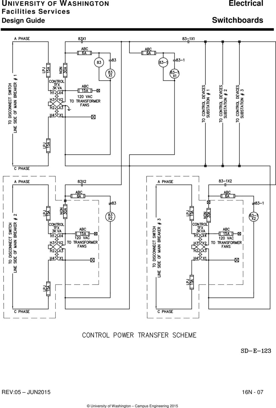
4 Network Protection Systems Refer to attached drawing, Typical Network Control Schematic as a guide for designing systems with network protection. Network protection equipment, devices, and operation shall comply with the requirement below and with the attached drawing and shall be included in the design documents. Deviations from this typical design and construction shall not be allowed unless approved by UW Campus Engineering. Consists of drawout power circuit breaker with electrical motor-charged mechanism closed and tripped by network relays for reverse current or undervoltage. AIC, frame and trip settings shall be provided by the drawings and verified by the protective device study. Relays shall, at a minimum, consist of a master-relay (a three-phase directional relay designed to provide highly sensitive directional tripping and to close the circuit breaker if the network voltage is favorable) and a phasing relay which permits breaker closing only when the phasing voltage lags the network voltage by up to 25 degrees or leads it by up to 100 degrees. The network relays function to automatically close the breaker only when voltage conditions are such that its associated transformer will supply load to the secondary loop, and to automatically open the breaker when power flows from the secondary loop to the network transformer. Provide rotary cam switch for manual-off-auto of network protection. Switch shall be manufactured by Electro-Switch Series 24 or an approved equal. (Typical switch characteristics: Heavy duty, rotary switch, UL listed, CSA certified, ESC standard 1000 compliance, ANSI/IEEE 323 compliance, IEEE compliance.) 1) Manual position: The electrically operated main breaker should be allowed to recharge but not to reclose. Reclosure shall be operator-initiated and only allowed if the network relays determine the closure is acceptable. 2) Off position: Network protection is inoperable. 3) Auto position: The network protection control relays should fully control the auto reclosure of the main breaker. For proper operation, network relaying shall work in conjunction with a stored energy device (86 relay). This locks the main breaker out from automatically reclosing after an overcurrent, short circuit or ground fault condition. Current sensing shall be true RMS current. Load demand reclosure controls as found on public utility networks should not be used. Reclosure should be permitted when the network voltages are correct and in proper rotation. Recloser will limit the number of breaker closure attempts to 3. Network protection relays shall be mounted on a base that allow the relay to be racked out for testing and maintenance. The relay shall operate in test mode in the racked-out position. 16N - 04 REV:05 JUN2015

5 Control Power Refer to attached drawings Typical Network Control Power Schematic as a guide for designing network protection control power. Network control power shall comply with the requirements below and with the attached drawing and shall be included in the design documents. Deviations from this typical design and construction shall not be allowed unless approved by UW Campus Engineering. For spot network and double-ended substations, provide relays and interlocking so that control power is available if one or more transformers are energized. Provide automatic "source select" scheme to ensure continuous control power to all breaker trip units, switchgear controls and electronic metering. Control power shall be derived from connections ahead of the main breaker(s). Provide emergency power for electronic meters and primary switch position monitoring contacts to ensure they operate during outages and during feeder switching operations. Emergency power shall be for electronic meters only and shall not be used to provide continuous control power for trip units and switchgear controls. Switchgear control power shall be derived using the source select scheme, mentioned above, ahead of the main breakers(s). Installation, Fabrication and Construction Leveling rails are required for drawout equipment to insure proper alignment. Installation is not complete until all electrical & mechanical tests are performed and passed. END OF DESIGN GUIDE SECTION REV:05 JUN N - 05

6 16N - 06 REV:05 JUN2015

7 REV:05 JUN N - 07
Submit shop drawings for equipment provided under this section Shop drawings shall indicate:
 Section 16435 - SWITCHBOARDS Introduction Part 1 - General Reference The work under this section is subject to requirements of the Contract Documents including the General Conditions, Supplementary Conditions,
The following components are common to most cubicles; this example is an ABB HK cubicle.
 4.0 CIRCUIT BREAKER CUBICLE Learning Objectives The circuit breaker cubicle is the component of the switchgear that holds the circuit breaker, and the controls and cabling for the distribution system.
SWITCHGEAR Section 16. SECTION INCLUDES This Section includes service and distribution switchboards rated 600 V and less.
 PART 1 - GENERAL SECTION INCLUDES This Section includes service and distribution switchboards rated 600 V and less. RELATED SECTIONS Division 16 Section "Basic Electrical Materials and Methods" for general
2a. IEM Indoor Metal Clad Medium Voltage Switchgear 15KV 16346-1. 2a. Section 16346 INDOOR METAL CLAD MEDIUM VOLTAGE SWTICHGEAR (Std.
 2a. IEM Indoor Metal Clad Medium Voltage Switchgear 15KV 16346-1 2a. Section 16346 INDOOR METAL CLAD MEDIUM VOLTAGE SWTICHGEAR (Std. Relays) Part 1 General 1.1 CONDITIONS AND REQUIREMENTS: A. Refer to
Sample - No Commercial Use
 COMPLETE REVISION October 2010 Electrical PIP ELSSG01 Design and Fabrication of Low-Voltage Metal-Enclosed AC Power Circuit Breaker Switchgear PURPOSE AND USE OF PROCESS INDUSTRY PRACTICES In an effort
A Comparison of Contemporary Electrical Distribution Equipment Standards. San Francisco IEEE Industry Applications Society May 26, 2009
 A Comparison of Contemporary Electrical Distribution Equipment Standards San Francisco IEEE Industry Applications Society May 26, 2009 What are Standards? Clearly defined performance characteristics Based
UNIVERSITY OF WASHINGTON Facilities Services Design Guide. Electrical. Metering and Monitoring. Basis of Design
 Basis of Design This section applies to the design, installation and integration of metering and monitoring equipment, including: hardware installed in the electrical service and distribution equipment,
Circuit Breakers and Switchgear. Thomas Greer Director of Engineering TLG Services
 Circuit Breakers and Switchgear Thomas Greer Director of Engineering TLG Services Presentation Outline Switchgear Definition Overcurrent Protection Devices Circuit Breaker Trip Curves and Coordination
Primary and Secondary Electrical Distribution Systems
 Primary and Secondary Electrical Distribution Systems Critical Facilities Round Table 12th Quarterly Membership Meeting June 2, 2006 David D. Roybal. P.E. Eaton Electrical Cutler-Hammer Products Utility
Secondary Unit Substations
 14 SWITCHGEAR Secondary Unit Substations Overview Siemens offers a wide variety of unit substation designs to meet customer requirements. A unit substation consists of one or more transformers mechanically
Low Voltage Switchgear
 Arc Resistant Switchgear n Insulated and isolated bus n Separation barriers and top venting n Breaker shutters 12 SWITCHGEAR Arc resistant metal-enclosed low voltage switchgear is an optional product offering
FFI. Advances in Medium and Low Voltage Power Distribution ESS Metron Expo and Technical Seminars. Presented By: Greg Pelster & Robert Schmid
 Advances in Medium and Low Voltage Power Distribution ESS Metron Expo and Technical Seminars Presented By: Greg Pelster & Robert Schmid FFI Ferrie, Franzmann Industries LOW VOLTAGE SWITCHGEAR & LOW VOLTAGE
MEDIUM VOLTAGE CE-BF SWITCHBOARDS. UP TO 40.5 kv. CE - BF - C - en - REV.00 2012.4
 CE - BF - C - en - REV.00 2012.4 APPLICATION CE-BF Switchbords up to 40.5 kv are designed for use in public and industrial distribution system up to 40,5KV for the operation and protection of lines, transformers,
Switchgear and Metal-Enclosed Bus
 Section 18 Switchgear and Metal-Enclosed Bus 180. SWITCHGEAR ASSEMBLIES 180A. General Requirements for All Switchgear. This rule covers general requirements for all switchgear. Examples of switchgear found
SWITCHGEAR. EGP Switchgear
 SWITCHEA EP Switchgear Cat generator set paralleling switchgear has been designed to integrate with Cat EMCP3 generator set controls. Now you can get greater efficiency, reliability and dependability all
LVA Take Offs in Bid Manager
 Electrical Sales and Distributor Training Low Voltage Assemblies (LVA) LVA Take Offs in Bid Manager This job aid helps to define some of the common selection questions that are encountered when configuring
Section 9: Power Distribution Equipment Bill Brown, P.E., Square D Engineering Services
 Section 9: Power Distribution Equipment Bill Brown, P.E., Square D Engineering Services Introduction Power Distribution Equipment is a term generally used to describe any apparatus used for the generation,
MCC Ratings. Voltage Rating
 MCC Ratings In addition to the various ratings of individual components used in motor control centers, the overall ratings of the motor control center must also be considered. Voltage Rating Motor control
Extend the Life of Existing Switchgear
 Extend the Life of Existing Switchgear January 2011/1910DB1002 by Hal Theobald, Product Manager Schneider Electric USA, Inc. Make the most of your energy SM Summary Introduction... p 3 Maintenance Requirements...
Learning Module 13: Panelboards and Switchboards. 101 Basic Series
 Learning Module 13: Panelboards and Switchboards 101 Basic Series What You Will Learn We ll step through each of these topics in detail: Introduction 4 Definitions 4 Similarities Between Panelboards and
SWITCHGEAR SOLUTIONS FOR MISSION CRITICAL APPLICATIONS. Presented by SAI Advanced Power Solutions
 SWITCHGEAR SOLUTIONS FOR MISSION CRITICAL APPLICATIONS POWER DISTRIBUTION RACKS IN A MISSION CRITICAL SYSTEM MODULES IN A MISSION CRITICAL SYSTEM UPS Convertor Main Inverter Load Battery BPC UPS & BATTERY
PIP ELSSG02 Design and Fabrication of Medium Voltage Metal-Clad Switchgear from 4.76 kv to 38 kv
 Electrical Design and Fabrication of Medium Voltage Metal-Clad Switchgear from 4.76 kv to 38 kv Table of Contents 1. Introduction...2 1.1 Purpose... 2 1.2 Scope... 2 2. References...2 2.1... 2 2.2 Industry
BERTHOLD ELECTRIC GENERATOR CONNECTION CABINET
 BERTHOLD ELECTRIC GENERATOR CONNECTION CABINET Berthold Electric Company s Generator Connection Cabinet provides a quick and convenient station to connect a portable generator to a facility s main service
SECTION 26 09 13 - POWER MONITOR FOR ELECTRICAL, STEAM CONDENSATE, AND WATER PART I - GENERAL
 SECTION 26 09 13 - POWER MONITOR FOR ELECTRICAL, STEAM CONDENSATE, AND WATER PART I - GENERAL 1.1 SUMMARY A. This section describes the requirements for the installation of Power Monitors and associated
SECTION 262413 SWITCHBOARDS
 PART 1 - GENERAL... 1 1.1 RELATED DOCUMENTS... 1 1.2 SUMMARY... 1 1.3 DEFINITIONS... 1 1.4 SUBMITTALS... 2 1.5 QUALITY ASSURANCE... 3 1.6 DELIVERY, STORAGE, AND HANDLING... 3 1.7 PROJECT CONDITIONS...
SOLAR PV STANDARD ELECTRICAL PLAN Microinverter Systems for Single Family Dwellings
 *** Provide this document to the inspector along with ALL system installation instructions *** Project Address: Scope: Standard plan for the installation of grounded microinverter solar PV systems, not
Alternate Methods to Short Circuit Breaker Coordination
 Alternate Methods to Short Circuit Breaker Coordination Nguyen Perez, PE Senior Electrical Engineer 2600 Douglas Road, Suite 301 Coral Gables, Florida 305.529.1515 (p) www.brplusa.com Importance in Healthcare
ELECTRIC METERING COMMERCIAL & INDUSTRIAL
 ELECTRIC METERING COMMERCIAL & 1.0 INDEX 1.0 INDEX 2.0 SCOPE 3.0 GENERAL REQUIREMENTS 4.0 METER LOCATIONS 5.0 UNDERGROUND TERMINATIONS 6.0 METERING TRANSFORMER ENCLOSURES 7.0 SINGLE CUSTOMER METER INSTALLATIONS
Unified requirements for systems with voltages above 1 kv up to 15 kv
 (1991) (Rev.1 May 2001) (Rev.2 July 2003) (Rev.3 Feb 2015) Unified requirements for systems with voltages above 1 kv up to 15 kv 1. General 1.1 Field of application The following requirements apply to
PREFACE. Your comments or suggestions are welcome and appreciated. They should be sent to:
 PREFACE UL developed the Dead-Front Switchboard Marking Guide for code authorities, electric utilities, contractors, installers, users, designers, and other interested parties to aid in understanding deadfront
Sentron Series Circuit Breakers
 Sentron Series Circuit Breakers Siemens Sentron Series circuit breakers are available in nine frame sizes: ED, FD, JD, LD, LMD, MD, ND, PD, and RD. Sentron Series circuit breakers have a wide range of
Addendum #2 Contract UK-11-13
 Addendum #2 Contract UK-11-13 Utilities Kingston Purchase and Replacement of Switchgear at Kingston Hydro Substation MS11 March 25, 2011 Delivered to: All RFP recipients Total number of pages: Nine (9)
Electrical. This section applies to the design and installation of building power distribution systems.
 Basis of Design This section applies to the design and installation of building power distribution systems. Design Criteria This section contains the architectural, structural and mechanical provisions
This section applies to the design and installation of transformers.
 ELECTRICAL: TRANSFORMERS BASIS OF DESIGN This section applies to the design and installation of transformers. Design Criteria 13.8-kV equipment shall be 15-kV class. Coordinate with short-circuit studies
Part 1 System Modeling & Studies for Existing Systems
 Part 1 System Modeling & Studies for Existing Systems Operation Technology, Inc. Copyright 2009 Result of rapid release of energy due to an arcing fault between two conductors. Bus voltages > 208V Temperatures
How to reduce exposure to arc flash hazards
 GE Energy Industrial Solutions How to reduce exposure to arc flash hazards Multiple solutions for new and existing facilities imagination at work Multiple Issues Today s power system engineer must not
Specification Guide. for RVAC. Direct Replacement. AC Medium Voltage. Circuit Breakers
 Specification Guide for RVAC Direct Replacement AC Medium Voltage Circuit Breakers Table of Contents 1.0 General Work Scope...3 2.0 Standards...3 3.0 Supplier Qualifications...4 4.0 Circuit Breaker Element
Bypass transfer switch mechanisms
 Power topic #6013 Technical information from Cummins Power Generation transfer switch mechanisms > White paper By Gary Olson, Director, Power Systems Development This paper describes the configuration
Hyperlinks are Inactive
 Prepared by: NIB/EOB PLANNING GUIDE FOR SINGLE CUSTOMER SUBSTATIONS SERVED FROM TRANSMISSION LINES 05503 Department: Electric T&D Section: T&D Engineering and Technical Support Approved by: G.O. Duru (GOD)
SECTION 16341 MEDIUM VOLTAGE SWITCHGEAR
 PART 1 - GENERAL 1.1 RELATED DOCUMENTS A. Drawings and general provisions of the Contract, including General and Supplementary Conditions, apply to this Section. 1.2 SUMMARY A. This Section includes metal-enclosed
QUESTIONS and ANSWERS RFB 745-15-9894, Metal Clad Switchgear and Power Control Room
 QUESTIONS and ANSWERS RFB 745-15-9894, Metal Clad Switchgear and Power Control Room 1) When you click on the UTHSCSA Drawing the site takes you to the E-1 drawing no other. Will there be other drawings
Fusible Disconnect Switch
 Circuit Breakers Circuit breakers are used in panelboards and switchboards to provide circuit protection and provide a means of energizing and de-energizing a circuit. Siemens Sentron molded case circuit
Introduction. Upon completion of Basics of Switchboards you should be able to: Explain the role of switchboards in a distribution system
 Table of Contents Introduction... 2 Distribution Systems... 4 Switchboard Definition... 9 Switchboard Construction... 12 Service Entrance Equipment... 18 Service Section... 20 Switchboard Grounding...
CONSOLIDATED EDISON CO. OF NEW YORK, INC. 4 IRVING PLACE NEW YORK, NY 10003 DISTRIBUTION ENGINEERING DEPARTMENT NETWORK SYSTEMS SECTION
 CONSOLIDATED EDISON CO. OF NEW YORK, INC. 4 IRVING PLACE NEW YORK, NY 10003 DISTRIBUTION ENGINEERING DEPARTMENT NETWORK SYSTEMS SECTION SPECIFICATION EO-2022 REVISION 15 DECEMBER 2009 EFFECTIVE DATE DECEMBER
Atlanta Chapter IEEE Industry Applications Society
 Atlanta Chapter IEEE Industry Applications Society Electrical Equipment Room Design Considerations presented at the Sheraton Buckhead Hotel Atlanta, Georgia November 20, 2006 Outline 1. Definitions 2.
ELECTRIC UTILITY SERVICE EQUIPMENT REQUIREMENTS COMMITTEE, EUSERC
 ELECTRICAL SERVICE REQUIREMENTS ELECTRIC UTILITY SERVICE EQUIPMENT REQUIREMENTS COMMITTEE, EUSERC TABLE OF CONTENTS TITLE SECTION NO. List of Approved Electric Utility Service Equipment Requirements Committee
Electrical Shore Connections / Cold Ironing
 STANDARD FOR CERTIFICATION No. 2.25 Electrical Shore Connections / Cold Ironing JULY 2014 The electronic pdf version of this document found through http://www.dnv.com is the officially binding version
Tmax MCCBs. Molded case circuit breakers. Tmax
 Molded case circuit breakers Introduction ABB is once again demonstrating its commitment to new product development and its superiority in product performance. Never before has the industry seen such high
How To Test A Power Switch On A Power Supply
 transfer switches Soft load Innovative, reliable, integrated solution Built with years of experience Powered with innovation Delivered with reliability A history of experience, innovation and reliability
Unit substation solutions with type SIMOSEC primary switches quick reference guide E50001-F710-A389-X-4A00. Answers for energy.
 Unit substation solutions with type SIMOSEC primary switches quick reference guide E50001-F710-A389-X-4A00 Answers for energy. Unit substation solution with type SIMOSEC primary switches, dry-type transformer
ZONE SELECTIVE INTERLOCKING (ZSI) APPLICATION AND TESTING GUIDE SIEMENS WL UL489 AND UL1066 AIR CIRCUIT BREAKERS
 APPLICATION AND TESTING GUIDE SIEMENS WL UL489 AND UL1066 AIR CIRCUIT BREAKERS") Definition: Zone Selective Interlocking (ZSI) - A method which allows two or more ground fault breakers to communicate with each other so that a short circuit or ground fault will be cleared by the breaker
Definition: Zone Selective Interlocking (ZSI) - A method which allows two or more ground fault breakers to communicate with each other so that a short circuit or ground fault will be cleared by the breaker
Engineers Edge, LLC PDH & Professional Training
 510 N. Crosslane Rd. Monroe, Georgia 30656 (770) 266-6915 fax (678) 643-1758 Engineers Edge, LLC PDH & Professional Training Copyright, All Rights Reserved Engineers Edge, LLC An Introduction to Interior
01.4IB.51200B PowlVac-AR Arc Resistant Switchgear. 5kV & 15kV 1200A, 2000A, 3000A, & 4000A Forced Cooled. Powered by Safety
 PowlVac-AR Arc Resistant Switchgear 1200A, 2000A, 3000A, & 4000A Forced Cooled Powered by Safety PowlVac-AR Arc Resistant Switchgear 01.4IB.51200B Contact Information Powell Electrical Systems, Inc. www.powellind.com
Cam switches. Page. Overview 4-2. ON-OFF switches, main switches, maintenance switches 4-3. Changeover switches, reversing switches 4-5
 Eaton Wiring Manual / Page Overview - ON-OFF switches, main switches, maintenance switches - Changeover switches, reversing switches - (Reversing) star-delta switches - Multi-Speed Switches - Interlock
For a phase-to-phase voltage between 100 V and 1000 V. The standard ratings are: 400 V - 690 V - 1000 V (at 50 Hz)
") 24 1. NETWORK CONFIGURATIONS definition Standard IEC 38 defines voltage ratings as follows: - Low voltage () For a phase-to-phase voltage between 100 V and 1000 V. The standard ratings are: 400 V - 690
24 1. NETWORK CONFIGURATIONS definition Standard IEC 38 defines voltage ratings as follows: - Low voltage () For a phase-to-phase voltage between 100 V and 1000 V. The standard ratings are: 400 V - 690
STANDARDS AND RATINGS FOR THE APPLICATION OF MOLDED CASE, INSULATED CASE, AND POWER CIRCUIT BREAKERS
 STANDARDS AND RATINGS FOR THE APPLICATION OF MOLDED CASE, INSULATED CASE, AND POWER CIRCUIT BREAKERS David D. Roybal, P.E. Senior Member, IEEE Cutler-Hammer, Inc. 3697 Mount Diablo Boulevard Lafayette,
Schneider Electric Services: life-cycle solutions for electrical distribution equipment. Scopes of Work for Electrical Acceptance Testing
 Scopes of Work for Electrical Acceptance Testing Schneider Electric Services: life-cycle solutions for electrical distribution equipment Make the most of your energy SM Scopes of Work for Electrical Acceptance
Rule 5.500 Fast Track Analysis for National Life Insurance Co.
 Rule 5.500 Fast Track Analysis for National Life Insurance Co. For a 500 kw Solar array to be located at 155 Northfield Street in Montpelier, Vermont Green Mountain Power Pam Allen Date: 5/31/13 SECTION
Short Circuit Current Calculations
 Introduction Several sections of the National Electrical Code relate to proper overcurrent protection. Safe and reliable application of overcurrent protective devices based on these sections mandate that
ELECTRICAL: AUTOMATIC TRANSFER SWITCHES
 AUTOMATIC TRANSFER SWITCHES BASIS OF DESIGN This section applies to the design of design and installation of automatic transfer switches. Design Criteria Clearly indicate in the drawings and specifications
SECTION 16346A METAL-CLAD MEDIUM VOLTAGE ARC RESISTANT SWITCHGEAR
 METAL-CLAD MEDIUM VOLTAGE ARC RESISTANT SWITCHGEAR PART 1 GENERAL 1.01 SCOPE A. The Contractor shall furnish and install the equipment as specified herein and as shown on the contract drawings. 1.02 RELATED
Product Description Full Voltage Starting Electric Fire Pump Controllers FTA1000
 Product Description Full Voltage Starting Electric Fire Pump Controllers FTA1000 Description Firetrol FTA1000 Full Voltage Fire Pump Controllers are intended for use with electric motor driven fi re pumps
What are the basic electrical safety issues and remedies in solar photovoltaic installations?
 What are the basic electrical safety issues and remedies in solar photovoltaic installations? Presented by: Behzad Eghtesady City of Los Angeles Department of Building and Safety Topics Covered Photovoltaic
Critical-Power Automatic Transfer Systems Design and Application
 Critical-Power Automatic Transfer Systems Design and Application Bill Brown, P.E., Jay Guditis, Square D Critical Power Competency Center 1. INTRODUCTION An important requirement of mission-critical electric
Suitable for Emergency, Peak and Prime Power System Applications. Low Voltage Automatic Transfer Switch Systems
 Suitable for Emergency, Peak and Prime Power System Applications Low Voltage Automatic Transfer Switch Systems THE POWER AUTHORITY THE POWER AUTHORITY ASCO s experience and commitment to excellence in
Switchgear Capabilities. NexGear is a Division of PowerSecure NASDAQ: POWR
 Switchgear Capabilities NexGear is a Division of PowerSecure NASDAQ: POWR Discussion Points Introducing PowerSecure Introducing NexGear Solutions Offered Scope of Services Examples of Work Q & A NexGear,
ELECTRICAL ENGINEERING DESIGN CRITERIA APPENDIX F
 ELECTRICAL ENGINEERING DESIGN CRITERIA APPENDIX F TABLE OF CONTENTS Appendix F - Electrical Engineering Design Criteria F.1 Introduction...F-1 F.2 Codes and Standards...F-1 F.3 Switchyard and Transformers...F-1
SECTION 16426C ARC RESISTANT DRAWOUT SWITCHGEAR (MAGNUM DS) LOW VOLTAGE
 LOW VOLTAGE") ARC RESISTANT DRAWOUT SWITCHGEAR (MAGNUM DS) LOW VOLTAGE PART 1 GENERAL 1.01 1.02 1.03 1.04 SCOPE The Contractor shall furnish and install, where indicated on the drawings, a deadfront type, arc resistant
ARC RESISTANT DRAWOUT SWITCHGEAR (MAGNUM DS) LOW VOLTAGE PART 1 GENERAL 1.01 1.02 1.03 1.04 SCOPE The Contractor shall furnish and install, where indicated on the drawings, a deadfront type, arc resistant
Advantages of Fixed Circuit Breaker Switchgear
 Advantages of Fixed Circuit Breaker Switchgear by Lionel Mackay, EDF Energy, and Mike Adams, Schneider Electric Ltd Introduction The purpose of this paper is to review the advantages of fixed circuit breaker
Power Plant Electrical Distribution Systems
 PDH Course E184 Power Plant Electrical Distribution Systems Gary W Castleberry, PE 2008 PDH Center 2410 Dakota Lakes Drive Herndon, VA 20171-2995 Phone: 703-478-6833 Fax: 703-481-9535 www.pdhcenter.com
Contents. Clean Control Center Harmonic Correction Unit. Selection Dimensions Specifications. Description
 lean ontrol enter Harmonic orrection Unit Technical Data Selection Dimensions Specifications ontents Description Page lean ontrol enter Specifications Harmonic orrection Unit...... 2 Sizing and Selection...........................................
Installation Instructions
 H5HK Series Installation Instructions 3 Phase Electric Heater Kits 7.5 and 0 TON Package A/C Systems Description Installation of 08/40V and 480V H5HK 3 Phase Heater Kits in 7.5 and 0 TON Packaged Air Conditioners.
Medium Voltage Products. ZN1 12 kv arc-proof air-insulated switchgear for primary distribution
 Medium Voltage Products ZN1 12 kv arc-proof air-insulated switchgear for primary distribution ZN1 an innovative switchgear for power distribution requirements ABB ZN1 primary distribution switchgear is
21 st Century Facilities
 Electrical Testing 21 st Century Facilities Facility Owners face tough challenges 24 X 7 reliability needed Non linear loads cause harmonics VFD Computers Switching transients disrupt operations Less customer
PS6500 Storage Arrays Rack Mount Instructions
 PS6500 Storage Arrays Rack Mount Instructions Part Number: R724M Rev. A01 Copyright 2010 Dell, Inc. All rights reserved. Dell is a trademark of Dell, Inc. EqualLogic is a registered trademark. All trademarks
Title 20 PUBLIC SERVICE COMMISSION. Subtitle 50 SERVICE SUPPLIED BY ELECTRIC COMPANIES. Chapter 02 Engineering
 Title 20 PUBLIC SERVICE COMMISSION Subtitle 50 SERVICE SUPPLIED BY ELECTRIC COMPANIES Chapter 02 Engineering Authority: Public Utility Companies Article, 2-121, 5-101 and 5-303, Annotated Code of Maryland.
Eaton Automatic Transfer Switches
 This is a photographic template your photograph should fit precisely within this rectangle. Eaton Automatic Transfer Switches Jody Grabowski Eaton ATS Product Line Sales Engineer February 1st, 2011 2008
Eaton s E-Series protective relay family
 E-Series protective relays Feeder distribution relays Motor relays Transformer relays Generator relays Eaton s E-Series protective relay family Microprocessor-based design Eaton s E-Series relay family
CalMod Design-Build Electrification Services
 SECTION 28 16 00 INTRUSION DETECTION SYSTEM PART 1 - GENERAL 1.1 DESCRIPTION A. This section describes the detailed technical requirements for the Intrusion Detection System (IDS), where the Contractor
Masterclad Medium Voltage Passive Arc-Resistant Switchgear
 Masterclad Medium Voltage Passive Arc-Resistant Switchgear Square D Masterclad medium voltage passive arc-resistant (AR) switchgear is designed with utilities and industrial customers in mind who demand
Applications. Remote Display Mounting Kits
 June 200 Sheet 105 Surge Protection Products TVSS General Description Clipper Power System Visor Series.1-5 Clipper Power System Visor Series General Description Eaton s Cutler-Hammer leading-edge surge
ETC TWO STAGE ELECTRONIC TEMPERATURE CONTROL
 RANCO INSTALLATION INSTRUCTIONS ETC TWO STAGE ELECTRONIC TEMPERATURE CONTROL Relay Electrical Ratings PRODUCT DESCRIPTION The Ranco ETC is a microprocessor-based family of electronic temperature controls,
What will MV switchgear look like in the future? by Jean-Marc Biasse
 What will MV switchgear look like in the future? by Jean-Marc Biasse Table of contents Introduction... 2 Brief history of the technologies used in medium voltage switchgear and control gear... 4 Evolution
SECTION 26 09 26 LOW VOLTAGE LIGHTING CONTROLS
 SECTION 26 09 26 LOW VOLTAGE LIGHTING CONTROLS PART 1 - GENERAL 1.01 RELATED DOCUMENTS: A. The Conditions of the Contract and applicable requirements of Division 1, "General Requirements", and Section
New SACE Emax 2 for UL 1066 From Circuit Breaker to Power Manager
 New SACE Emax 2 for UL 1066 From Circuit Breaker to Power Manager 2 1SDC200039B0201 New SACE Emax 2 for UL 1066 Circuit breakers switch power SACE Emax 2 manages it. SACE Emax 2 is the new benchmark of
IRRIGATION PUMPING Table of Contents - Section 900
 IRRIGATION PUMPING Table of Contents - Section 900 PARAGRAPH 900.1 GENERAL 1 900.2 METERING REQUIREMENTS 1 900.3 CUSTOMER S CONTROL EQUIPMENT 2 900.4 SERVICE CONDUCTOR REQUIREMENTS 2 900.5 RECOMMENDATIONS
SCADA Controlled Multi-Step Automatic Controlled Capacitor Banks & Filter Banks
 SCADA Controlled Multi-Step Automatic Controlled Capacitor Banks & Filter Banks Introduction SCADA (Supervisory Controlled and Data Acquisition) controlled multi-step metalenclosed automatic capacitor
REQUIREMENTS FOR CUSTOMER-OWNED PRIMARY SERVICES SUPPLIED AT 4 kv TO 35 kv PRIMARY GUIDE
 BC Hydro Distribution Standards REQUIREMENTS FOR CUSTOMER-OWNED PRIMARY SERVICES SUPPLIED AT 4 kv TO 35 kv PRIMARY GUIDE JUNE 2010 Changes Visible Edition This document shows all changes that have been
GROWTH MANAGEMENT DEPARTMENT 201 SE 3 rd ST, (Second Floor), Ocala, FL 34471 (352) 629-8421; FAX: (352) 629-8264
, Ocala, FL 34471 (352) 629-8421; FAX: (352) 629-8264") BUILDING CODE GUIDELINES FOR ELECTRICAL INSPECTIONS Building Code compliance is the obligation of design professionals and/or contractors. Plan Review and Inspection Guidelines are intended to be used
BUILDING CODE GUIDELINES FOR ELECTRICAL INSPECTIONS Building Code compliance is the obligation of design professionals and/or contractors. Plan Review and Inspection Guidelines are intended to be used
Chapter 1. Network Structures
 Chapter 1 Network Structures Definition Standard IEC 60038 defines voltage ratings as follows: Low voltage (): for a phase-to-phase voltage of between 100 V and 1,000 V, the standard ratings are: 400 V
OVR Three-Phase Recloser and PCD Control Style Guide 1VAL264001-SG October 13, 2009 Revision F
 OVR Three-Phase Recloser and PCD Control Style Guide 1VAL264001-SG October 13, 2009 Revision F The OVR three-phase recloser style guide aids in the proper selection of your OVR three-phase style number.
ECE 586b Course Project Report. Auto-Reclosing
 ECE 586b Course Project Report Auto-Reclosing Srichand Injeti May 5, 2008 Department Of Electrical and computer Engineering University Of Western Ontario, London Ontario Table of contents 1. Introduction...1
SURGE PROTECTIVE DEVICES (SPDs) LOW VOLTAGE AC INTEGRATED SURGE PROTECTION FOR ELECTRICAL DISTRIBUTION SYSTEMS SECTION 16671A SECTION 16671A
 LOW VOLTAGE AC INTEGRATED SURGE PROTECTION FOR ELECTRICAL DISTRIBUTION SYSTEMS SECTION 16671A SECTION 16671A") SURGE PROTECTIVE DEVICES (SPDs) INTEGRATED UNITS LOW VOLTAGE AC SURGE PROTECTION FOR ELECTRICAL DISTRIBUTION SYSTEMS PART 1 GENERAL 01 02 03 SCOPE The Contractor shall furnish and install the Surge Protective
SURGE PROTECTIVE DEVICES (SPDs) INTEGRATED UNITS LOW VOLTAGE AC SURGE PROTECTION FOR ELECTRICAL DISTRIBUTION SYSTEMS PART 1 GENERAL 01 02 03 SCOPE The Contractor shall furnish and install the Surge Protective
SUGGESTED SPECIFICATION for Series 185 Service Entrance Rated Automatic Transfer Switches
 SUGGESTED SPECIFICATION for Series 185 Service Entrance Rated Automatic Transfer Switches PART 1 GENERAL 1.01 Scope Optional Standby Power Generator Systems A. Furnish and install automatic transfer switches
Utility Distribution Systems
 Utility Distribution Systems 6/2012 A0011037 1 WARRANTY This equipment is warranted to be free from defects in materials and workmanship, under normal use and service, for a period of 12 months from date
Power-Zone 4 Arc Resistant Low Voltage Switchgear
 Power-Zone 4 Arc Resistant Low Voltage Switchgear with ArcBlok Technology Make the most of your energy SM Workplace safety 2 I Power-Zone 4 Arc Resistant Low Voltage Switchgear Five to ten arc flash explosions
DOCUMENT 009102 - ADDENDUM NO. 2. Issued to all Bidders: Date: February 3, 2015. Contract Name: 13,800-Volt and 480-Volt Switchgear
 DOCUMENT 009102 - ADDENDUM NO. 2 Issued to all Bidders: Date: February 3, 2015 Contract Name: 13,800-Volt and 480-Volt Switchgear SUA Bid No.: #21-14/15 This addendum forms a part of the Bid described
COMPARISON OF ANSI/IEEE AND IEC REQUIREMENTS FOR LOW- VOLTAGE SWITCHGEAR
 COMPARISON OF ANSI/IEEE AND IEC REQUIREMENTS FOR LOW- VOLTAGE SWITCHGEAR Copyright Material IEEE Paper No. PCIC 2003-13 Eddie Wilkie Eaton Cutler-Hammer 3990 Old Tasso Road NE Cleveland, TN 37312 USA Abstract
Federal Wage System Job Grading Standards for Electric Power Controlling, 5407. Table of Contents
 Federal Wage System Job Grading Standards for Electric Power Controlling, 5407 Table of Contents WORK COVERED... 2 WORK NOT COVERED...2 TITLES... 2 GRADE LEVELS... 2 SPECIAL ADDITIONAL RESPONSIBILITIES...