Product Description Full Voltage Starting Electric Fire Pump Controllers FTA1000
|
|
|
- Joleen Montgomery
- 8 years ago
- Views:
Transcription
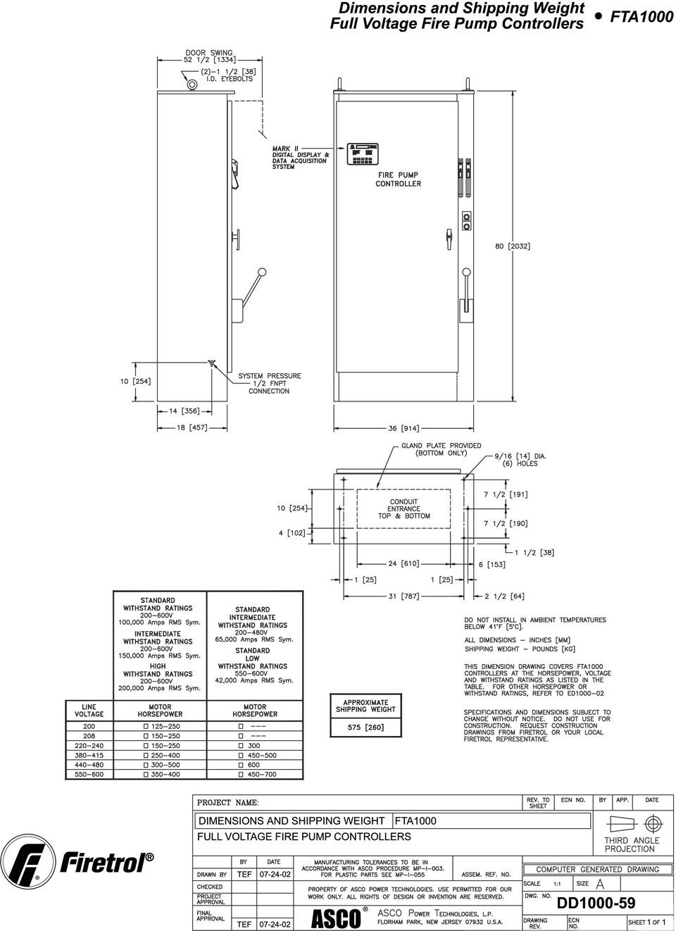
1 Product Description Full Voltage Starting Electric Fire Pump Controllers FTA1000 Description Firetrol FTA1000 Full Voltage Fire Pump Controllers are intended for use with electric motor driven fi re pumps where the capacity of the power source permits full voltage starting. Full voltage is applied to the motor as soon as the controller is actuated. The controller monitors, displays and records fi re pump system information. Full voltage starting is simple and low cost and is preferred whenever the utility or emergency generator set will permit this type of starting. Approvals Firetrol fi re pump controllers are listed by Underwriters Laboratories, Inc., in accordance with UL218, Standard for Fire Pump Controllers, CSA, Standard for Industrial Control Equipment, and approved by Factory Mutual. They are built to meet or exceed the requirements of the approving authorities as well as NEMA and the latest editions of NFPA 20, Installation of Centrifugal Fire Pumps, and NFPA 70, National Electrical Code. Standard Features The following are included as standard with each controller: Voltage surge protector Main Disconnect Switch sized for connected motor horsepower and voltage Fire pump Circuit Breaker Motor contactor Emergency Manual Run Mechanism to mechanically close motor contactor contacts in an emergency condition Built-in Start and Stop push-buttons to bypass automatic start circuits Door mounted display/interface panel featuring a 40 Character Vacuum Fluorescent Display, Membrane Type User Control Push-buttons and easy to read LED Indicators Single handle Isolating Disconnect Switch/Circuit Breaker mechanism POWER ON LED PUMP RUN LED PHASE FAILURE LED PHASE REVERSAL LED LOW PRESSURE LED DELUGE OPEN LED INTERLOCK ON LED TRANSFER SWITCH NORMAL LED (If unit ordered with Automatic Power Transfer Switch) TRANSFER SWITCH EMERGENCY LED (If unit ordered with Automatic Power Transfer Switch) EMERGENCY ISOLATING SWITCH OFF LED (If unit ordered with Automatic Power Transfer Switch) Minimum Run Timer / Off Delay Timer Daylight Savings Time Option Weekly Test Timer Elapsed Time Meter Digital Pressure Display USB Host Controller and Port Solid State Pressure Transducer Data Log Event Log (3000 Events) True RMS Metering with simultaneous 3 phase display of amps and volts Disk Error message Disk Near Full message Pressure Error message Motor Over 320% message Local Start message Remote Start message Emergency Start message Fail To Start message Undervoltage message Overvoltage message High Speed Open Serial Communications Port NEMA Type 2 enclosure Suitable for use as Service Equipment

2 Specifications Electric Fire Pump Controllers FTA Main Fire Pump Controller The main fire pump controller shall be a factory assembled, wired and tested unit and shall conform to all the requirements of the latest edition of NFPA 20, Standard for the Installation of Stationary Pumps for Fire Protection and NFPA 70, National Electrical Code. The controller shall be listed by Underwriters Laboratories, Inc., in accordance with UL218, Standard for Fire Pump Controllers, CSA, and Canadian Standards Association CSA-C22.2, Standard for Industrial Control Equipment (culus), approved by Factory Mutual and approved by the City of New York for fire pump service. Starting Method The controller shall be of the combined manual and automatic type designed for: Full Voltage Starting Solid State Soft Starting Wye (Star)-Delta Open Transition Starting Wye (Star)-Delta Closed Transition Starting Part Winding Starting Primary Resistance Reduced Voltage Starting Autotransformer Reduced Voltage Starting of the fire pump motor having the horsepower, voltage, phase and frequency rating shown on the plans and drawings. The controller components shall be housed in a NEMA Type 2 (IEC IP11) drip-proof, wall mounted enclosure. Withstand Ratings (Short Circuit Current Ratings) All controller components shall be front mounted, wired and front accessible for maintenance. The minimum withstand rating of the controllers shall not be less than 100,000 Amps RMS Symmetrical at Volts*. If the available system fault current exceeds these ratings, the controllers shall be supplied with a withstand rating of 150,000 or 200,000 Amps RMS Symmetrical, as required. *Note: 100,000 Amp withstand rating not available in some larger horsepowers. Consult factory for details. Isolation Switch and Circuit Breaker The controller shall include a motor rated combination isolating disconnect switch/circuit breaker, mechanically interlocked and operated with a single, externally mounted handle. When moving the handle from OFF to ON, the interlocking mechanism shall sequence the isolating disconnect switch ON first, and then the circuit breaker. When the handle is moved from ON to OFF, the interlocking mechanism shall sequence the circuit breaker OFF first, and then the isolating disconnect switch. The isolating disconnect switch/circuit breaker shall be mechanically interlocked so that the enclosure door cannot be opened with the handle in the ON position except by a hidden tool operated defeater mechanism. The isolating disconnect switch/circuit breaker shall be capable of being padlocked in the OFF position for installation and maintenance safety, and shall also be capable of being locked in the ON position without affecting the tripping characteristics of the circuit breaker. The controller door shall have a locking type handle and three point cam and roller vault type hardware. The circuit breaker trip curve adjustment shall be factory set, tested and sealed for the full load amps of the connected motor. The circuit breaker shall be capable of being field tested to verify actual pick up, locked rotor, and instantaneous trip points after field installation without disturbing incoming line and load conductors. Operator Interface The fire pump controller shall feature an operator interface with user keypad. The interface shall monitor and display motor operating conditions, including all alarms, events, and pressure conditions. All alarms, events, and pressure conditions shall be displayed with a time and date stamp. The display shall be a 2- line, 20-character, vacuum fluorescent, dot matrix type designed to allow easy viewing from all angles and in all light conditions. The display and interface shall be NEMA rated for Type 2, 3R, 4, 4X, and 12 protection and shall be fully accessible without opening the controller door. The display and user interface shall utilize multiple levels of password protection for system security. A minimum of 3 password levels shall be provided. The display shall be capable of being programmed for any language. Ammeter/Voltmeter The fire pump controller operator interface shall be capable of displaying true RMS digital motor voltage and current measurements for all three phases simultaneously. Displays requiring pushbutton and selector switches to toggle between phases or current and voltage shall not be accepted. Voltage and current shall be measured by True RMS technology to provide the most accurate measurement for all sine waves, including nonsinusoidal waveforms. Average responding meters will not be accepted. Digital Status/Alarm Messages The digital display shall indicate text messages for the status and alarm conditions of: Motor On Sequential Start Time Minimum Run Time Local Start / Off Delay Time Remote Start Fail to Start System Battery Low Under Voltage Over Voltage Locked Rotor Trip Over Frequency Emergency Start Motor Over 320% Drive Not Installed Motor Overload Disk Error Printer Error Disk Near Full Pressure Error The Sequential Start Timer and Minimum Run Timer/ Off Delay Timer shall be displayed as numeric values reflecting the value of the remaining time.
, approved by Factory Mutual and approved by the City of New York for fire pump service.")
3 LED Visual Indicators LED indicators, visible with the door closed, shall indicate: Power On Emerg. Isolating Switch Open Pump Running Low System Pressure Alarm Transfer Switch Normal Deluge Open Transfer Switch Emergency Phase Failure Phase Reversal Interlock On Data Logging The digital display shall monitor the system and log the following data: Motor Calls/Starts Elapsed Motor Run Time Last Trip Currents Elapsed Power On Time Last Breaker Trip Maximum Run Currents Minimum Voltages Minimum Run Currents Maximum Voltages Last Motor Run Time Last Phase Failure Last Start Currents Last Phase Reversal Min/Max Frequency Min/Max Pressure The START, STOP and SYSTEM PRESSURE shall be digitally displayed and adjustable through the user interface. The pressure transducer shall be mounted inside the controller to prevent accidental damage. The pressure transducer shall be directly pipe mounted to a bulkhead pipe coupling without any other supporting members. Field connections shall be made externally at the controller coupling to prevent distortion of the pressure switch element and mechanism. Operation A digitally set On Delay (Sequential Start) timer shall be provided as standard. Upon a call to start, the user interface shall display a message indicating the remaining time value of the On Delay timer. The controller shall be field programmable for manual stop automatic stop. If set for automatic stopping, the controller shall allow the user to select either a Minimum Run Timer or an Off Delay Timer. Both timers shall be programmable through the user interface. Event Recording Memory - The controller shall record all operational and alarm events to system memory. All events shall be time and date stamped and include an index number. The system memory shall have the capability of storing 3000 events and allow the user access to the event log via the user interface. The user shall have the ability to scroll through the stored messages in groups of 1, 10, or 100. USB Host Controller - The controller shall have a built-in USB Host Controller. A USB port capable of accepting a USB Flash Memory Disk (aka: flash drive, thumb drive, memory stick, etc..) shall be provided. The controller shall save all operational and alarm events to the flash memory on a daily basis. Each saved event shall be time and date stamped. The total amount of historical data saved shall solely depend on the size of the flash disk utilized. The controller shall have the capability to save settings and values to the flash disk via the user interface. Serial Communications - The controller shall feature a RS485 serial communications port for use with 2 or 4 wire Modbus RTU communications. Solid State Pressure Transducer The controller shall be supplied with a solid state pressure transducer with a range of psi ( bar) ±1 psi. The solid state pressure switch shall be used for both display of the system pressure and control of the fire pump controller. Systems using analog pressure devices or mercury switches for operational control will not be accepted. SP ( )

4 Sequence of Operation Full Voltage Fire Pump Controllers FTA1000 Introduction The following information is in reference to Wiring Schematic, Publication WS Note: Firetrol schematics are drawn showing the equipment in a de-energized state. Energizing The Controller 1. Close the isolating switch/circuit breaker by moving the handle to the ON position. Note: The unmarked, red, Interlock jumper wire, located between terminals #1 & #10 on the Relay PC board, (TB1), will prevent the MarkII unit from starting the electric motor automatically. This jumper wire should only be removed after the pressure settings have been input, and the system pressurized at, or above the Stop set point. 2. The factory programmed MarkII unit will begin initialization. Upon completion, the display will confirm system pressure, the time, date, and Interlock ON, which is an alarm condition and will cause the yellow alarm LED to flash. Any other existing alarm conditions (low system pressure, phase reversal, phase failure, deluge open), will also be sequentially and continuously displayed at this time, until each is rectified. 3. With the interlock jumper wire still in place, the electric motor can only be started by depressing the START push-button, located on the flange of the controller enclosure, or by engaging the Emergency Run Mechanism. After all alarm conditions have been rectified, and the system pressurized at or above the Stop pressure setting, then the interlock jumper may be removed for the controller s automatic operation ( standby ). With the interlock jumper removed, a drop in system pressure to the MarkII s set Start point, will start the electric motor. 4. The deluge valve contacts are only operational if the factory jumper has been removed and a normally closed deluge valve contact has been placed between terminals 1 and 8 of the Relay PC board, (TB1). The Remote Start is only operational if a normally open, momentarily closed contact is wired to terminals 6 and 7 of the Relay PC board, (TB1). If engaged, the Emergency Run Mechanism will cause the pump motor to run as described in the Emergency Starting and Stopping section. Automatic Start and Stop 1). The controller s pressure transducer initiates the automatic start circuits for the pump motor. When pressure falls at, or below the MarkII Start setting, relay 1CR is energized. 1CR normally open contact closes, allowing voltage to the motor starter circuits (see section Pump Motor Starting Sequence for more information) The minimum run time is a part of the MarkII s Menu, Timer Settings. The minimum run timer s factory setting is 10 minutes. In this mode, minimum run time begins when the pressure falls at or below the Start set point, calling for the pump motor to run. When pressure drops, this signals the MarkII to output via the Relay PC board, directly to the 1CR relay coil. The relay s normally open contact closes, allowing line voltage to the coil of the 1M contactor. The contactor s 3 normally open contacts close, allowing 3 phase line voltage to the electric motor, and the motor runs. Simultaneously, the minimum run function of the MarkII is activated, maintaining voltage on the 1CR relay coil, and keeping the motor running until the 10 minutes expire. At this time, with pressure restored at or above the Stop set point, 1CR relay coil will de-energize, re-opening its normally open contact, de-energizing the 1M contactor coil. It s 3 normally open contacts will reopen, causing the motor to de-energize and stop. If pressure is restored at, or above the Stop set point of the MarkII, and even if minimum run time has not yet expired, the manual STOP push button located on the flange of the controller can be depressed to manually stop the engine. This also resets the minimum run time function of the MarkII. Manual Start and Stop The pump motor may be manually started by using either the START push-button mounted on the flange of the enclosure or by using a normally open, momentarily closed, remote start push-button connected to terminals 6 and 7. When the START push-button is depressed, or a remote start signal is seen through terminals 6 & 7, the MarkII will output through the relay pc board to 1CR relay coil and the pump motor will be energized and run as described in section Automatic Start & Stop. The MarkII s minimum run time feature will not be activated. The pump motor will continue to run until the STOP push-button is depressed. When the STOP push-button is depressed, 1CR relay coil is de-energized, interrupting the voltage to the 1M contactor coil, which causes the motor to stop. Deluge Valve Operation To operate the controller utilizing a deluge valve, the wire jumper between terminals 1 and 8 must be removed and a normally closed, open to run deluge valve contact wired in its place.

5 When the deluge valve contact opens, relay 1CR is energized, closings it s normally open contact to the 1M contactor coil, and the motor runs. When the deluge valve contact closes, relay 1CR is de-energized, re-opening it s normally open contact, deenergizing the 1M contactor, and the motor stops. Shutdown Interlock Operation The shutdown interlock, if used, is a normally open, closed to interlock contact wired to terminals 1 and 10. When the interlock contact is closed, relay 1CR cannot be energized by inputs to the MarkII from the pressure transducer, or the deluge valve. The controller may be started manually by depressing the manual START push button. See the specific starting operation for more details. Pump Motor Starting Sequence Whenever relay 1CR is energized, it s normally open contact closes, allowing voltage to the coil of the motor starting contactor. During full voltage starting the following sequence occurs. 1CR normally open contact closes, energizing contactor 1M. 1M connects motor terminals T1, T2, and T3 to the power source. This starts the motor in the full voltage configuration, in which the pump motor draws 100% of its normal inrush current and supplies 100% of its normal starting torque. Emergency Starting and Stopping The controller is equipped with an emergency run mechanism for use in the event of a coil burnout or other electrical problem which would prevent normal starting of the pump motor. The mechanism attempts to both electrically and mechanically start the pump motor. When the emergency run mechanism is utilized, a e-run contact is closed, energizing 1M coil. This, in effect, attempts to electrically start the pump motor. The emergency run mechanism also manually closes the 1M contactor, starting the motor. This will run the motor as long as the main three phase power is available. If the pump motor is running via the emergency run mechanism, DO NOT release the mechanism to stop the motor. Place the isolating switch/circuit breaker handle in the off position, then release the emergency run mechanism. Releasing the mechanism while the motor is running could result in damage to the motor or the motor contactor. Note: The emergency run mechanism is not intended for, nor should it be used as a testing device. Its sole purpose is to attempt to start the pump motor in the event of a failure. SQ ( )

6
7

8

9

10

11

Product Description Primary Resistance Starting Electric Fire Pump Controllers FTA1500
 Product Description Primary Resistance Starting Electric Fire Pump Controllers FTA1500 Description Firetrol FTA1500 Primary Resistance Fire Pump Controllers use resistors in the line to reduce line voltage
Product Description Digital Solid State Starting Electric Fire Pump Controllers FTA1930
 Product Description Digital Solid State Starting Electric Fire Pump Controllers FTA1930 Description Firetrol FTA1930 Digital Solid State Starting Fire Pump Controllers feature soft start, soft stop and
WITH POWER TRANSFER SWITCH STANDARD SUBMITTAL PACKAGE
 WITH POWER TRANSFER SWITCH STANDARD SUBMITTAL PACKAGE SBP1930-61 FTA1930 Digital Solid State Starting Electric Fire Pump Controllers Product Description Fire Pump Controllers for Business-Critical Continuity
Product Description Full Voltage Starting Electric Fire Pump Controllers FTA1000
 Product Description Full Voltage Starting Electric Fire Pump Controllers FTA1000 Description Firetrol FTA1000 Full Voltage Fire Pump Controllers are intended for use with electric motor driven fire pumps
FTA1100-J DIESEL ENGINE FIRE PUMP CONTROLLERS STANDARD SUBMITTAL PACKAGE
 FTA1100-J DIESEL ENGINE FIRE PUMP CONTROLLERS STANDARD SUBMITTAL PACKAGE SBP1100J FTA1100J Diesel Engine Fire Pump Controllers Product Description Description Firetrol combined automatic and manual Mark
Limited Service Fire Pump Controllers Features
 Must Be Installed Per Applicable Code and Manufacturers Recommendations Limited Service Fire Pump Controllers Features 1-1 FD20 Full Voltage - Limited Service with Plus Microprocessor Power I/O Board Transformers
MANUAL FOR MODEL MP30 ELECTRIC MOTOR DRIVEN LIMITED SERVICE CONTROLLER
 MANUAL FOR MODEL MP30 ELECTRIC MOTOR DRIVEN LIMITED SERVICE CONTROLLER Starting Serial No. "LA" This manual provides General Information, Installation, Operation, Maintenance and System Set-Up Information
Fire Pump Controllers Remote Alarm Panels
 Fire Pump Controllers Remote Alarm Panels Remote Alarm Panels 1.8 Remote Alarm Panels FDAP-M Electric... DFDAP-M Diesel... Product Specifications... 2 6 9 Features 1-1 DFDAP-M / FDAP-M Remote Alarm Panel
Limited Service Pump Controllers (Produced after July 18, 2006) Installation- Start Up - Service
 Installation- Start Up - Service") Instruction Bulletin Limited Service Pump Controllers (Produced after July 18, 2006) Installation- Start Up - Service This instruction is a guide for personnel involved with Maintenance, Engineering and
Instruction Bulletin Limited Service Pump Controllers (Produced after July 18, 2006) Installation- Start Up - Service This instruction is a guide for personnel involved with Maintenance, Engineering and
DORMA MODEL PS-406BB POWER SUPPLY INSTALLATION INSTRUCTIONS
 Features: INSTALLATION Install in accordance with NFPA 70. DORMA MODEL PS-406BB POWER SUPPLY INSTALLATION INSTRUCTIONS Up to 1.95 Amps Load Capacity Class 2 Rated Outputs Overload, Over Voltage, and Short
Transfer Equipment Controls
 Control Types Manual Transfer Switches Nonautomatic Transfer Switches Automatic Transfer Switches The type of control system for the transfer switch will vary depending on the type of switching equipment
SUGGESTED SPECIFICATION for Series 185 Service Entrance Rated Automatic Transfer Switches
 SUGGESTED SPECIFICATION for Series 185 Service Entrance Rated Automatic Transfer Switches PART 1 GENERAL 1.01 Scope Optional Standby Power Generator Systems A. Furnish and install automatic transfer switches
26 3213.13 Diesel Engine Driven Generators Page 1 of 6
 Last Update: December 8, 2014 A. Description of System Consultant s Handbook Page 1 of 6 1. Provide a diesel engine driven electric generating unit, factory assembled, tested and certified to operate at
LTR Series Uninterruptible Power Systems 700 VA - 2.1 KVA. General Specification
 08/17/12 Rev2 LTR Series General Specification 700 VA to 2.1 KVA 1.0 General LTR Series Uninterruptible Power Systems 700 VA - 2.1 KVA General Specification This specification describes the features and
Products and solutions for pumping, irrigation and piping
 Products and solutions for pumping, irrigation and piping 100% electricity www.lovatoelectric.com Tra dition and Innovation LOVATO Electric S.p.A. - Bergamo - Italy Since 1922 The first LOVATO Electric
Operational Overview and Controls Guide
 DOCUMENT: ECSEQ2-1 EFFECTIVE: 02/14/07 SUPERSEDES: 02/26/03 Operational Overview and Controls Guide Standard Two or Three Pump Type VFD Booster Controls 6700 Best Friend Road. Norcross, GA 30071. (770)
Operational Overview and Controls Guide. Two or Three Pump IronHeart Lite with Variable Frequency Drives
 DOCUMENT: ECSEQ6-0 EFFECTIVE: 09/23/10 SUPERSEDES: Operational Overview and Controls Guide Two or Three Pump IronHeart Lite with Variable Frequency Drives 6700 Best Friend Road. Norcross, GA 30071. (770)
Bypass transfer switch mechanisms
 Power topic #6013 Technical information from Cummins Power Generation transfer switch mechanisms > White paper By Gary Olson, Director, Power Systems Development This paper describes the configuration
BT300 HVAC Drives Conventional Bypass (C-Bypass) Options
 Options") BT300 HVAC Drives Conventional Bypass (C-Bypass) Options Description The BT300 Conventional Bypass is a companion package for the family of BT300 HVAC Drives. For information on the family of BT300 HVAC
BT300 HVAC Drives Conventional Bypass (C-Bypass) Options Description The BT300 Conventional Bypass is a companion package for the family of BT300 HVAC Drives. For information on the family of BT300 HVAC
AUTOMATIC TRANSFER SWITCH CONTROL UNIT OPERATOR S MANUAL
 ATS-220 AUTOMATIC TRANSFER SWITCH CONTROL UNIT OPERATOR S MANUAL For Use in 208 to 240 Volts Single and 3 Phase ATS Systems With 110Volt AC or DC Control Motors and selenoids 4501 NW 27 ave Miami FL 33142
PARAGON ELECTRIC, INC. LIQUID LEVEL CONTROLLER USER MANUAL MODELS: LLC-I, LLC-II AND TELEMETRY OPTIONS
 PARAGON ELECTRIC, INC. LIQUID LEVEL CONTROLLER USER MANUAL MODELS: LLC-I, LLC-II AND TELEMETRY OPTIONS 2 Table of Contents Safety... 4 Introduction... 5 Features and Benefits... 6 Control Overview... 7
SECTION 13XXX CONTROL DESCRIPTION (DICP Models 02-412NC, 412, 622, 826, 1030)
") PART 1 - GENERAL SECTION 13XXX CONTROL DESCRIPTION (DICP Models 02-412NC, 412, 622, 826, 1030) 1.01 SUMMARY This section describes the operation and control of a drip irrigation system. The major components
PART 1 - GENERAL SECTION 13XXX CONTROL DESCRIPTION (DICP Models 02-412NC, 412, 622, 826, 1030) 1.01 SUMMARY This section describes the operation and control of a drip irrigation system. The major components
WYE-DELTA AND SOLID STATE STARTER APPLICATION GUIDE
 WHITE PAPER WYE-DELTA AND SOLID STATE STARTER APPLICATION GUIDE EXPLANATION AND ASSISTANCE FOR APPLYING SOLID STATE SOFT STARTERS IN TRADITIONAL REDUCED VOLTAGE APPLICATIONS Introduction..............................................................2
SECTION 26 29 23 VARIABLE FREQUENCY DRIVES
 SECTION 26 29 23 VARIABLE FREQUENCY DRIVES PART 1 GENERAL 1.01 SCOPE A. Furnish and install individual freestanding variable frequency AC drives (VFD) as shown on the Drawings and specified herein. 1.02
Eaton s E-Series protective relay family
 E-Series protective relays Feeder distribution relays Motor relays Transformer relays Generator relays Eaton s E-Series protective relay family Microprocessor-based design Eaton s E-Series relay family
Conventional Fire Detection and Extinguishant Control System Specification
 Conventional Fire Detection and Extinguishant Control System Specification Page 1 of 9 Scope Furnish a complete 24VDC Conventional, electrically supervised, combined fire detection and extinguishant release
..OR How To Protect your 3-Phase Equipment Investment with 3-Phase Monitors from Time Mark...
 ..OR How To Protect your 3-Phase Equipment Investment with 3-Phase Monitors from Time Mark... TIME MARK CORPORATION 11440 EAST PINE STREET TULSA, OK 74116 USA tel 918 438-1220 fax 918 437-7584 www.time-mark.com
PowerCommand Paralleling System Digital MasterControl
 PowerCommand Paralleling System Digital MasterControl Description The PowerCommand Digital MasterControl is a systemlevel controller designed to interface directly with Cummins Power Generation PowerCommand
EATON Diesel Plus Diesel Engine Fire Pump Controller
 O & M Manual IM05805019K-002 Effective April 2015 EATON Diesel Plus Diesel Engine Fire Pump Controller Powering Business Worldwide O & M Manual IM05805019K-002 Effective April 2015 EATON Diesel Plus Diesel
Application Engineering
 Application Engineering February 2011 Electronic Unit Controller Table of Contents 1. Introduction and Features... 2 1.1 Technical Specifi cations... 3 1.2 Pressure Probe Error Bypass... 3 1.3 Bump Start...
ABC-1000 Automatic Boiler Level Controller Operation and Installation Manual
 QUALITY STEAM SPECIALTIES SINCE ABC-1000 Automatic Boiler Level Controller Operation and Installation Manual Section: C500 Bulletin: C500.40 Date: 06-26-01 Supersedes: New PRODUCT DESCRIPTION: The Clark-Reliance
NELSON VOLTAGE MONITOR INSTALLATION & PROGRAMMING MANUAL
 NELSON VOLTAGE MONITOR INSTALLATION & PROGRAMMING MANUAL CONTENTS GENERAL INFORMATION...3 INSTALLATION...3 FIELD WIRING...4 PROGRAMMING...4 Circuit Monitor Options...5 Power Frequency...5 Alarm Silence
MODEL 5010 DUAL CHANNEL SMOKE/FIRE DETECTION MODULE
 DESCRIPTION MODEL 5010 DUAL CHANNEL SMOKE/FIRE DETECTION MODULE DESCRIPTION The SST Model 5010 Two Channel Smoke/Fire Detection Module provides two independent detection input channels for the NOVA-5000
AC-115 Compact Networked Single Door Controller. Installation and User Manual
 AC-115 Compact Networked Single Controller Installation and User Manual December 2007 Table of Contents Table of Contents 1. Introduction...5 1.1 Key Features... 6 1.2 Technical Specifications... 7 2.
Safety Requirements Specification Guideline
 Safety Requirements Specification Comments on this report are gratefully received by Johan Hedberg at SP Swedish National Testing and Research Institute mailto:johan.hedberg@sp.se -1- Summary Safety Requirement
Understanding Emergency Power Off (EPO)
") Understanding Emergency Power Off (EPO) White Paper #22 Executive Summary Emergency Power Off (EPO) is the capability to power down a piece of electronic equipment or an entire installation from a single
Understanding Emergency Power Off (EPO) White Paper #22 Executive Summary Emergency Power Off (EPO) is the capability to power down a piece of electronic equipment or an entire installation from a single
CONSTRUCTION STANDARDS DIVISION 23 HEATING VENTILATING AND AIR CONDITIONING
 PART 1-GENERAL 1.01 DESCRIPTION A. This specification is to cover a complete Variable Frequency motor Drive (VFD) consisting of a pulse width modulated (PWM) inverter designed for use on a standard NEMA
Sentron Series Circuit Breakers
 Sentron Series Circuit Breakers Siemens Sentron Series circuit breakers are available in nine frame sizes: ED, FD, JD, LD, LMD, MD, ND, PD, and RD. Sentron Series circuit breakers have a wide range of
MANUAL FOR MODEL MP300 to MP700 ELECTRIC MOTOR DRIVEN FIRE PUMP CONTROLLERS
 MANUAL FOR MODEL MP300 to MP700 ELECTRIC MOTOR DRIVEN FIRE PUMP CONTROLLERS Starting Serial No. "RA" This manual provides General Information, Installation, Operation, Maintenance and System Set-Up Information
ATS - Automatic Changeover
 ATS - Automatic Changeover Manufacturers of Electrical Switchgear Choosing an Automatic Transfer System Switchgear Systems offer a variety of solutions for multiple supply switching needs. As well as our
Electric Panel Pump Control System. Operation, Maintenance and Installation Manual
 Manual No. 5EP-OM1-1 Electric Panel Pump Control System Operation, Maintenance and Installation Manual INTRODUCTION... 1 RECEIVING AND STORAGE... 1 DESCRIPTION OF OPERATION... 1 INSTALLATION... 2 SEQUENCE
LMR Plus Electric Fire Pump Controllers Custom Messages
 Instructions on how to save for uploading to the LMR Plus controller. Up to ten (10) different messages can be uploaded to the LMR Plus controller and displayed on the bottom (fourth line) of the LCD display.
Medical Vacuum Systems-PXMI
 Medical Vacuum Systems-PXMI Please read and save these instructions. Read carefully before attempting to assemble, install, operate or maintain the product described. Protect yourself and others by observing
ATC-300 Automatic Transfer Switch Controller
 ATC-300 Technical Data New Information Technical Data Page 2 Effective: May 2004 ATC-300 Introduction The Cutler-Hammer ATC-300 from Eaton s Electrical business is a comprehensive, multi-function, microprocessor-based
FAIRBANKS NIJHUIS FIRE PUMPS. www.fairbanksnijhuis.com
 FAIRBANKS NIJHUIS FIRE PUMPS www.fairbanksnijhuis.com FAIRBANKS NIJHUIS Long established as a leading fire pump manufacturer, Fairbanks Nijhuis offers a broad range of horizontal and vertical split case,
Vilter motor starter solutions The NEW industry standard in motor starter packages
 Vilter motor starter solutions The NEW industry standard in motor starter packages Electrical safety by design Built to Underwriters Laboratory (UL) 508A UL Standard for Safety for Industrial Control Panels.
Bussmann. All-In-One Module. Bussmann Power Module Switch. How to configure Part Numbers: Step 1: Select Switch Amperage 1
 How to configure Part Numbers: Step : Select Switch Amperage Power Module Switch Rating (Amps) Power Module Switch Catalog No. 30 3 60 6 00 200 2 400 4 Step 2: Select Options Needed 5 Bussmann Power Module
The HVAC SOLUTION DELIVERING POWER...SAVING ENERGY
 The HVAC SOLUTION DELIVERING POWER...SAVING ENERGY PowerGate - Cost effective solutions for F 1 Horsepower Rating 001 1-40 HP (208V) 075 1-75 HP (480V) Input Voltage 2V 208-240V 4V 380-480V Disconnect
USER MANUAL CHARGING STATIONS FOR ELECTRIC VEHICLES
 USER MANUAL CHARGING STATIONS FOR ELECTRIC VEHICLES 204.CAxxx 204.CBxxx 204.UBxxx 204.WBxxx MP36289 1 ZP90856-GB-6 INDICE 1 SYSTEM DESCRIPTION... 4 1.1 MODES OF OPERATION... 4 2 USER INTERFACE... 6 2.1
Automatic Transfer Switch Controller
 Automatic Transfer Switch Controller Decision-Makerr MPAC 1500 Model KBS with Decision-Makerr MPAC 1500 Controller Applicable Models Model Description KCS Standard-Transition Any Breaker ATS ] KCP Programmed-Transition
SUBJECT: How to wire a motor starter Number: AN-MC-004 Date Issued: 2/08/2005 Revision: Original
 SUBJECT: How to wire a motor starter Number: AN-MC-004 Date Issued: 2/08/2005 Revision: Original A motor starter is a combination of devices to allow an induction motor to start, run and stop according
Industrial-Grade UPS System Heavy-duty power protection for harsh industrial environments
 Industrial-Grade UPS System Heavy-duty power protection for harsh industrial environments Model #: SM2000RMX Heavy-duty, industrial-grade metal housings Shock and vibration rated to MIL-STD-810D 19 inch
GTEC transfer switch open transition
 GTEC transfer switch open transition 40-1250 Amp Description The GTEC automatic transfer switch combines reliability and flexibility in a small, economical package for transferring loads between a utility
Product Specification instalert Rapid Messenger Variable Message Sign
 instalert 2 units to cover any application instalert 18 (ia18): 18 x 28 full matrix instalert 24: (ia24): 24 x 60 full matrix Size, Weight without battery ia18: 30 x 20 x 2.74, 29 lbs ia24: Folds to fits
How to read this guide
 How to read this guide The following shows the symbols used in this Quick start guide with descriptions and examples. Symbol Description Example P oint Reference Caution [ ] This symbol explains information
32:(5#5$7,1* 4833#USP283#+] 4;33#USP293#+] 3ULPH 113 kva, 90 kw 124 kva, 99 kw 6WDQGE\ 114 kva, 91 kw 125 kva, 100 kw
![32:(5#5$7,1* 4833#USP283#+] 4;33#USP293#+] 3ULPH 113 kva, 90 kw 124 kva, 99 kw 6WDQGE\ 114 kva, 91 kw 125 kva, 100 kw](/thumbs/30/14614129.jpg "32:(5#5$7,1* 4833#USP283#+] 4;33#USP293#+] 3ULPH 113 kva, 90 kw 124 kva, 99 kw 6WDQGE\ 114 kva, 91 kw 125 kva, 100 kw") ,1'8675,$/#*(16(7 6HULHV#'9#448 32:(5#5$7,1* 4833#USP283#+] 4;33#USP293#+] 3ULPH 113 kva, 90 kw 124 kva, 99 kw 6WDQGE\ 114 kva, 91 kw 125 kva, 100 kw Generator set consisting of engine and alternator mounted
,1'8675,$/#*(16(7 6HULHV#'9#448 32:(5#5$7,1* 4833#USP283#+] 4;33#USP293#+] 3ULPH 113 kva, 90 kw 124 kva, 99 kw 6WDQGE\ 114 kva, 91 kw 125 kva, 100 kw Generator set consisting of engine and alternator mounted
Horizontal Split Case Fire Pumpset Electric Motor Driven 50 Hz
 SERIES Horizontal Split Case Fire Pumpset Electric Motor Driven 50 Hz Selected Models INTRODUCTION Lubi offers LHCE series state-of-the-art fire pumpset with electric motor driven, horizontal split case
Specifying a Variable Frequency Drive s
 Specifying a Variable Frequency Drive s Put on by Bruce Reeves and Jeremy Gonzales Dykman Electrical Covering the Western US For all of your VFD and Soft Start and Motor Needs How To Specify a Variable
Cam switches. Page. Overview 4-2. ON-OFF switches, main switches, maintenance switches 4-3. Changeover switches, reversing switches 4-5
 Eaton Wiring Manual / Page Overview - ON-OFF switches, main switches, maintenance switches - Changeover switches, reversing switches - (Reversing) star-delta switches - Multi-Speed Switches - Interlock
AuCom s IMS2 soft starters are a total motor starting solution, combining highlevel functionality with ease of use:
 AuCom s IMS2 soft starters are a total motor starting solution, combining highlevel functionality with ease of use: advanced soft start and soft stop control protection functions that operate even when
VARIABLE FREQUENCY DRIVES Revised 4/30/2015 23 81 07-1 Mechanical Systems
 SECTION 23 81 07 - VARIABLE FREQUENCY DRIVES PART 1 - GENERAL 1.1 SUMMARY A. This section includes all variable frequency drives. All standard and optional features shall be included within the VFD panel
Horizontal Split Case Fire Pumpset Diesel Engine Driven
 SERIES Horizontal Split Case Fire Pumpset Diesel Engine Driven Selected Models INTRODUCTION Lubi offers LHCD series state-of-the-art fire pumpset with diesel engine driven, horizontal split case pump.
OWNERS MANUAL. Status Monitor. for Windows 95, 98, ME, NT 4, 2000 & XP. SIGNALCRAFTERS TECH, INC. www.signalcrafters.com
 OWNERS MANUAL Status Monitor for Windows 95, 98, ME, NT 4, 2000 & XP SIGNALCRAFTERS TECH, INC. www.signalcrafters.com 57 Eagle Rock Avenue, East Hanover, NJ 07936 Tel: 973-781-0880 or 800-523-5815 Fax:
TEMON 8-C. Doc. N MO-0370-ING TEMPERATURE MONITOR DEVICE TYPE TEMON 8-C OPERATION MANUAL. Microener - Copyright 2010 FW 2.2 Date 01.12.2008 Rev.
 TEMPERATURE MONITOR DEVICE TYPE TEMON 8-C OPERATION MANUAL Microener - Copyright 2010 FW 2.2 Date 01.12.2008 Rev. 0 1. Generality 3 2. Introduction 3 3. Accessories and Options 3 4. Installation 3 5. Connection
SmartOnline Expandable Rack / Tower UPS System Online, double-conversion protection for mission critical applications
 SmartOnline Expandable Rack / Tower UPS System Online, double-conversion protection for mission critical applications Model #: SU3000RTXL3U 3000VA online 3U rack / tower UPS Enhanced serial communications
Panorama. Softstarters The complete range
 Panorama Softstarters The complete range Why does soft starting matter? Controlling industrial electricity. The vast majority of the world s industrial applications are driven by motors. It is estimated
HP 5 Microprocessor Control for Mammoth Water Source Heat Pumps
 HP 5 Microprocessor Control for Mammoth Water Source Heat Pumps Operation and Maintenance Manual Model: 71028004 Applies to: Single Circuit Water-to-Water Twin Circuit Units Without DDC Controls MAMM WHSP
LTM-1338B. Plus Communications Manual
 LTM-1338B Plus Communications Manual 2000. Best Power, Necedah, Wisconsin All rights reserved. Best Power The System Setup option from the Main Menu on the front panel is passwordprotected. The default
FIRE ALARM SYSTEM. A. Shop drawings shall be submitted as follows: 1. Manufacturer's published literature. for aspproval.
 Polk School District Specifications for the New Fire Alarm in the Existing Building Eastside Elementary School FIRE ALARM SYSTEM 1.01 SUBMITTALS A. Shop drawings shall be submitted as follows: 1. Manufacturer's
How To Test A Power Switch On A Power Supply
 transfer switches Soft load Innovative, reliable, integrated solution Built with years of experience Powered with innovation Delivered with reliability A history of experience, innovation and reliability
ALARM ANNUNCIATOR ME - 3010 INSTRUCTION MANUAL
 ALARM ANNUNCIATOR ME - 3010 INSTRUCTION MANUAL INTRODUCTION... 2.. TECHNICAL DATA... 3 ACCESSORIES... 5. INSTALLATION... 7 OPERATION... 12. TECHNICAL INFORMATION... 13 MAINTENANCE... 14. CONFIGURATIONS...
FireSeeker Fire Alarm Control Panel Model FS-250 Programming Manual
 FireSeeker Fire Alarm Control Panel Model FS-250 Programming Manual P/N 315-049403-1 Siemens Building Technologies Fire Safety Table Of Contents Introduction...1 The Access levels...1 User Level...1 Maintenance
32VFD Variable Frequency Drives for Centrifugal Chillers
 32VFD 32VFD Variable Frequency Drives for Centrifugal Chillers ENERGY-SAVING CONTROL FOR CENTRIFUGAL CHILLERS Reduce energy consumption in your existing centrifugal chiller Your chiller was specified to
Guidelines on the Short Circuit Current Rating for Industrial Control Panels
 usa.siemens.com/sccr Guidelines on the Short Circuit Current Rating for Industrial Control Panels Technical Paper for Practical Applications White Paper I October 2014 As per NEC Edition 2014, and UL508A
Daker DK 1, 2, 3 kva. Manuel d installation Installation manual. Part. LE05334AC-07/13-01 GF
 Daker DK 1, 2, 3 kva Manuel d installation Installation manual Part. LE05334AC-07/13-01 GF Daker DK 1, 2, 3 kva Index 1 Introduction 24 2 Conditions of use 24 3 LCD Panel 25 4 Installation 28 5 UPS communicator
ELECTRICAL SAFETY. The standard unit for measuring electrical current.
 ELECTRICAL SAFETY Introduction The following sections provide general safety guidelines and procedures for electrical safety. This chapter covers the following topics: TOPIC PAGE General Electrical Safety
APC Smart-UPS RT. GUIDE SPECIFICATIONS FOR 3000VA, 5000VA and 6000 VA Smart-UPS RT 230VAC Uninterruptible Power Supply
 APC Smart-UPS RT GUIDE SPECIFICATIONS FOR 3000VA, 5000VA and 6000 VA Smart-UPS RT 230VAC Uninterruptible Power Supply PART 1 - GENERAL 1.1 SUMMARY A. This specification describes the operation and functionality
Installation and Operation Back-UPS 1250, 1300, 1500
 Installation and Operation Back-UPS 1250, 1300, 1500 Inventory bu001a Safety and General Information This unit is intended for indoor use only. Do not operate this unit in direct sunlight, in contact with
SmartPro 120V 2.2kVA 1.92kW Line-Interactive Sine Wave UPS, SNMP, Webcard option, 2U Rack/Tower, LCD, USB, DB9 Serial
 SmartPro 120V 2.2kVA 1.92kW Line-Interactive Sine Wave UPS, SNMP, Webcard option, 2U Rack/Tower, LCD, USB, DB9 Serial MODEL NUMBER: SMART2200RM2U Highlights 2.2kVA / 2200VA / 1920W line interactive 2U
Model #: SMART2200CRMXL
 Tripp Lite 1111 West 35th Street Chicago, IL 60609 USA Telephone: +(773) 869 1234 E-mail: saleshelp@tripplite.com Model #: SMART2200CRMXL SmartPro Compact Rackmount UPS System - Precision Protection for
GPD 506/P5 Start-up Procedure and Checklist
 GPD 506/P5 Start-up Procedure and Checklist Preparation for GPD506/P5 Drive Start-Up...2 HVAC Start-Up Procedure for GPD 506/P5 WITH Bypass Option:...4 HVAC Start-Up Procedure for GPD 506/P5 WITHOUT Bypass
SURGE PROTECTIVE DEVICES (SPDs) LOW VOLTAGE AC INTEGRATED SURGE PROTECTION FOR ELECTRICAL DISTRIBUTION SYSTEMS SECTION 16671A SECTION 16671A
 LOW VOLTAGE AC INTEGRATED SURGE PROTECTION FOR ELECTRICAL DISTRIBUTION SYSTEMS SECTION 16671A SECTION 16671A") SURGE PROTECTIVE DEVICES (SPDs) INTEGRATED UNITS LOW VOLTAGE AC SURGE PROTECTION FOR ELECTRICAL DISTRIBUTION SYSTEMS PART 1 GENERAL 01 02 03 SCOPE The Contractor shall furnish and install the Surge Protective
SURGE PROTECTIVE DEVICES (SPDs) INTEGRATED UNITS LOW VOLTAGE AC SURGE PROTECTION FOR ELECTRICAL DISTRIBUTION SYSTEMS PART 1 GENERAL 01 02 03 SCOPE The Contractor shall furnish and install the Surge Protective
543-0032-00, 943-0032-00. User s Manual
 543-0032-00, 943-0032-00 User s Manual 1 Comfort Alert Diagnostics Faster Service And Improved Accuracy The Comfort Alert diagnostics module is a breakthrough innovation for troubleshooting heat pump and
How To Operate A Gec Transfer Switch Open Transition 40 2000 Amp Power Supply
 GTEC Transfer switch open transition 40 2000 amp Description GTEC transfer switches combine reliability and flexibility in a small, economical package for transferring loads between a utility and a generator
Back-UPS Pro 1300/1500 Installation and Operation
 Back-UPS Pro 1300/1500 Installation and Operation Inventory Safety Do not install the Back-UPS in direct sunlight, in excessive heat, humidity, or in contact with fluids. Connect the battery bu059a bu058a
1R / 4-BUTTON SERIES
 Button 1 1R / 4-BUTTON SERIES VEHICLE SECURITY SYSTEM Standard Features: Two 4-Button Remote Transmitters Status indicator (LED) Valet / override switch Multi-tone siren Dual stage impact detector Remote
The following components are common to most cubicles; this example is an ABB HK cubicle.
 4.0 CIRCUIT BREAKER CUBICLE Learning Objectives The circuit breaker cubicle is the component of the switchgear that holds the circuit breaker, and the controls and cabling for the distribution system.
TSn SERIES Surge Protective Device
 Page: 1 of 8 TSn SERIES Surge Protective Installation & Operation Manual 3621 Saunders Avenue www.systems.us Ph 804.355.1100 Richmond, VA 23227 4354 Sales@Systems.us Fax 804.355.8900 Page: 2 of 8 Quick
SmartPro 120V 500VA 300W Line-Interactive UPS, SNMP, Webcard, 1U Rack/Tower, USB, DB9 Serial
 SmartPro 120V 500VA 300W Line-Interactive UPS, SNMP, Webcard, 1U Rack/Tower, USB, DB9 Serial MODEL NUMBER: SMART500RT1U Description Tripp Lite's SMART500RT1U intelligent, line-interactive rack/tower uninterruptible
Control/Communicator Installation Manual
 DAS NETWORX NX-8 Control/Communicator Installation Manual Page General Description... 2 Ordering Information... 2 Option Definitions... 2 Programming the LED Code Pads... 4 Programming the NX-8... 8 Types
Programming A PLC. Standard Instructions
 Programming A PLC STEP 7-Micro/WIN32 is the program software used with the S7-2 PLC to create the PLC operating program. STEP 7 consists of a number of instructions that must be arranged in a logical order
Circuit Breakers and Switchgear. Thomas Greer Director of Engineering TLG Services
 Circuit Breakers and Switchgear Thomas Greer Director of Engineering TLG Services Presentation Outline Switchgear Definition Overcurrent Protection Devices Circuit Breaker Trip Curves and Coordination
ETC TWO STAGE ELECTRONIC TEMPERATURE CONTROL
 RANCO INSTALLATION INSTRUCTIONS ETC TWO STAGE ELECTRONIC TEMPERATURE CONTROL Relay Electrical Ratings PRODUCT DESCRIPTION The Ranco ETC is a microprocessor-based family of electronic temperature controls,
IRRIGATION PUMPING Table of Contents - Section 900
 IRRIGATION PUMPING Table of Contents - Section 900 PARAGRAPH 900.1 GENERAL 1 900.2 METERING REQUIREMENTS 1 900.3 CUSTOMER S CONTROL EQUIPMENT 2 900.4 SERVICE CONDUCTOR REQUIREMENTS 2 900.5 RECOMMENDATIONS
Bulletin 150 Smart Motor Controllers SMC-3 Smart Motor Controller
 Overview/Modes of Operation Bulletin 150 Smart Motor Controller The SMC-3 is a compact, simple to use, solid-state motor controller designed to operate 3-phase motors. It features a built-in overload relay
Suitable for Emergency, Peak and Prime Power System Applications. Low Voltage Automatic Transfer Switch Systems
 Suitable for Emergency, Peak and Prime Power System Applications Low Voltage Automatic Transfer Switch Systems THE POWER AUTHORITY THE POWER AUTHORITY ASCO s experience and commitment to excellence in
Centro-Matic Automatic Lubrication Systems System Controls
 Selecting the right controls for your automated lubrication system is one of the last steps in the design process. Several different models may be chosen to control power-operated pumps, depending on the
Smart Pro Rack/Tower UPS Intelligent, line interactive network power management system
 Smart Pro Rack/Tower UPS Intelligent, line interactive network power management system Model #: SMART500RT1U 500VA line interactive 1U rack/tower UPS 7 outlets with 1 switchable load bank Simultaneous
SECTION 13850 DETECTION AND ALARM
 SECTION 13850 DETECTION AND ALARM PART 1 GENERAL 1.01 SUMMARY A. Section Includes 1. Control Panel 2 Associated Equipment B. Products Installed But Not Supplied Under This Section 1. Section 16140 - Wiring
Hydraulic Controllers, PHC, HS
 General In This Section PHC HS Hydraulic Controllers, PHC, HS General Model HMC-1000 controllers, industry recognized for over a decade, provide field proven reliability for all hydraulic elevator applications.