Basic Problem: Map a 3D object to a 2D display surface. Analogy - Taking a snapshot with a camera
|
|
|
- Isabel Arnold
- 10 years ago
- Views:
Transcription
1 3D Viewing Basic Problem: Map a 3D object to a 2D display surface Analogy - Taking a snapshot with a camera Synthetic camera virtual camera we can move to any location & orient in any way then create a 2D image of a 3D object Page 1 of 22

2 Steps for Viewing in 3D 1. choose a projection type parallel or perspective 2. establish the view specify the viewing parameters position of the viewers eye, location of the view plane two coordinate systems (scene & viewing) 3. clipping in three dimensions Remove portions of the 3D scene that are not candidates for ultimate display clip objects against a 3D view volume 4. project the scene onto the computer display project the view volume onto a 2D projection plane (window) 5. map this image to the viewport (display) Clip against view volume 3D world-coordinate output primitives Clipped world coordinates Project onto projection plane Transform into viewport in 2D device coords. 2D device coordinates Page 2 of 22
 5.")
3 Projections Projections transform points in a coordinate system of dimension n into points in a coordinate system of dimension less than n (eg. 3D 2D) Straight projection rays (projectors) that start from a center of projection and pass through each point of an object and intersect a projection plane There are two basic types of projections: 1. A 2. A B B A B A B COP Parallel Perspective We will deal only with planar geometric projections: projecting onto a plane rather than a curved surface uses straight projectors rather than curved Page 3 of 22

4 A B A B 1. Parallel projection centre of projection (COP) at infinite distance projectors are all parallel specify the direction of projection (DOP) instead of COP less realistic (no perspective foreshortening) good for exact measurements and parallel lines remain parallel angles remain constant only on faces parallel to the projection plane used in engineering and architecture Page 4 of 22
 good for exact measurements and parallel lines remain parallel angles remain")
5 A B A B COP 2. Perspective Projection projectors meet at the center of projection (COP) (eye, camera ) finite distance between COP and projection plane approximation of human visual system or photographic system gives perspective foreshortening size of an object varies inversely with the distance of that object from the center of projection adds realism causes distortion not useful for accurate shapes or measurements Page 5 of 22

6 Parallel Projections - two main types: orthographic and oblique Orthographic Projections Direction of projection (DOP) is perpendicular to the projection plane. most common types involve the projection plane being perpendicular to a principle axis: front-elevation (front-view) (z-axis) top-elevation (top or plan view) (y-axis) side-elevation (side-view) (x-axis) each projection only shows one face of an object, therefore the 3D nature is difficult to comprehend Page 6 of 22
 top-elevation (top or plan view) (y-axis) side-elevation (side-view) (x-axis) each projection only shows one")
7 Orthographic projection matrixes: xy 0xz 0yz front-elevation top-elevation side elevation *easy, just discard one of the coordinates (e.g. for a front-elevation, discard the z coordinates) Examples: Page 7 of 22
 Examples: http://mane.mech.virginia.")
8 Axonometric Orthographic Projection use projection planes that are NOT perpendicular to a principal axis therefore, can show several faces of an object at once Three classes of axonometric proejctions depending on the number of major axes which are forshortened 1. Isometric Projection special case of an axonometric projection direction of the projection is at equal angles to all axes all three major axes are foreshortened equally if projection plane normal is (dx, dy, dz), then: dx = dy = dz or +-dx = +-dy = +-dz there are only eight directions (one in each octant that can satisfy this condition Page 8 of 22
, then: dx = dy = dz or +-dx = +-dy = +-dz there are only eight directions (one in each")
9 2. Dimetric Projections direction of the projection makes equal angles with two of the axes dx = dy or dy = dz or dx = dz only lines drawn along the two equally forshortened axes are scaled to the same factor Page 9 of 22

10 3. Trimetric Projections direction of the projection makes different angles with all three axes can be used to display different orientations by placing different amounts of emphasis on the faces Page 10 of 22

11 Oblique Projection direction of projection is NOT perpendicular to the projection plane the projection plane is perpendicular to a principal axis Page 11 of 22

12 two types: cavalier projection: α = 45 all sides will maintain equal lenghts edges can be measured directly looks elongated cabinet projection: α = 63.4 projection of a line perpendicular to the projection plane are ½ their actual length looks more realistic Page 12 of 22

13 Perspective Projections COP A B A B objects of equal size at different distances from the viewer will be projected at different sizes (nearer objects will appear closer) Page 13 of 22
 Page 13")
14 any lines of the object NOT parallel to the projection plane BUT parallel in the object (scene) will converge to a point vanishing point if the set of lines is parallel to one of the three principal axes, the vanishing point is called an axis vanishing point perspective projections are categorized by their number of principal vanishing points (therefore the number of axes the projection plane cuts) Page 14 of 22
 Page 14")
15 1-point perspective one vanishing point projection plane cuts 1 axis only (perpendicular), other 2 axes are parallel to the plane. 2-point perspective two vanishing points projection plane cuts 2 axes Page 15 of 22

16 3-point perspective three vanishing points projection plane cuts all 3 axes Vanishing point examples Page 16 of 22

17 Relationships among various types of projections: Page 17 of 22

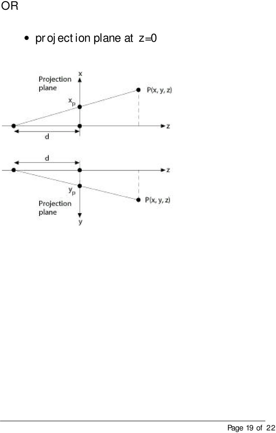
18 Perspective Planar Geometric Projections For simplicity: projection plane is normal to the z-axis at z=d Page 18 of 22

19 OR projection plane at z=0 Page 19 of 22
20 Specifying a View Volume Projection plane -> View Plane View reference point (VRP) a point on the view plane View plane normal (VPN) normal of the view plane (the viewplane can be in front of, cut through, or be behind objects) Given a view plane, a window which contents are mapped to the viewport (e.g. clipping) specify min & max window coordinates axes part of 3D Viewing Reference Coordinate (VRC) System one axis (n) is VPN one axis (v) is coincident with projection of VUP parallel to VPN Page 20 of 22
 specify min & max window coordinates axes part of 3D Viewing Reference Coordinate (VRC) System one axis (n) is VPN")
21 one axis (u) is defined such that u, v, and n form a right handed coordinate system min & max of u & v define the window PRP projection reference point - center of projection for perspective viewing - direction of projection for parallel viewing (specified DOP from the PRP to the center of the window) Page 21 of 22
22 Page 22 of 22
Realtime 3D Computer Graphics Virtual Reality
 Realtime 3D Computer Graphics Virtual Realit Viewing and projection Classical and General Viewing Transformation Pipeline CPU Pol. DL Pixel Per Vertex Texture Raster Frag FB object ee clip normalized device
CS 4204 Computer Graphics
 CS 4204 Computer Graphics 3D views and projection Adapted from notes by Yong Cao 1 Overview of 3D rendering Modeling: *Define object in local coordinates *Place object in world coordinates (modeling transformation)
From 3D to 2D: Orthographic and Perspective Projection Part 1
 From 3D to 2D: Orthographic and Perspective Projection Part 1 History Geometrical Constructions Types of Projection Projection in Computer Graphics Andries van Dam September 13, 2001 3D Viewing I 1/34
Geometry for Computer Graphics
 Computer Graphics and Visualisation Geometry for Computer Graphics Student Notes Developed by F Lin K Wyrwas J Irwin C Lilley W T Hewitt T L J Howard Computer Graphics Unit Manchester Computing Centre
3D Viewing. Chapter 7. Projections. 3D clipping. OpenGL viewing functions and clipping planes
 3D Viewing Chapter 7 Projections 3D clipping OpenGL viewing functions and clipping planes 1 Projections Parallel Perspective Coordinates are transformed along parallel lines Relative sizes are preserved
4BA6 - Topic 4 Dr. Steven Collins. Chap. 5 3D Viewing and Projections
 4BA6 - Topic 4 Dr. Steven Collins Chap. 5 3D Viewing and Projections References Computer graphics: principles & practice, Fole, vandam, Feiner, Hughes, S-LEN 5.644 M23*;-6 (has a good appendix on linear
How to read Plans and Do Basic Drawings
 How to read Plans and Do Basic Drawings Workshop session W1 10.00 Site Orientation Exercise 10.10 Drawing Conventions 10.45 Can drawings Distort the Truth? 11.30 Summary + Coffee 11.45 Simple Drawing Techniques
Monash University Clayton s School of Information Technology CSE3313 Computer Graphics Sample Exam Questions 2007
 Monash University Clayton s School of Information Technology CSE3313 Computer Graphics Questions 2007 INSTRUCTIONS: Answer all questions. Spend approximately 1 minute per mark. Question 1 30 Marks Total
Wallingford Public Schools - HIGH SCHOOL COURSE OUTLINE
 Wallingford Public Schools - HIGH SCHOOL COURSE OUTLINE Course Title: Computer Aided Drafting & Design Course Number: 7163 Department: Career and Technical Education Grade(s): 9-12 Level(s): Academic Credit:
521493S Computer Graphics. Exercise 2 & course schedule change
 521493S Computer Graphics Exercise 2 & course schedule change Course Schedule Change Lecture from Wednesday 31th of March is moved to Tuesday 30th of March at 16-18 in TS128 Question 2.1 Given two nonparallel,
SOEM 024: Computer Aided Design. E. Rozos
 SOEM 024: Computer Aided Design E. Rozos 3D Design with AutoCAD 2002 Isometric Drawings 3D coordinates, views Wire-frame 3D modelling, extruding Primitive objects Boolean operators Terminology Boolean
The Geometry of Perspective Projection
 The Geometry o Perspective Projection Pinhole camera and perspective projection - This is the simplest imaging device which, however, captures accurately the geometry o perspective projection. -Rays o
Traditional Drawing Tools
 Engineering Drawing Traditional Drawing Tools DRAWING TOOLS DRAWING TOOLS 1. T-Square 2. Triangles DRAWING TOOLS HB for thick line 2H for thin line 3. Adhesive Tape 4. Pencils DRAWING TOOLS 5. Sandpaper
Transformations in the pipeline
 Transformations in the pipeline gltranslatef() Modeling transformation ModelView Matrix OCS WCS glulookat() VCS CCS Viewing transformation Projection transformation DCS Viewport transformation (e.g. pixels)
Practice Final Math 122 Spring 12 Instructor: Jeff Lang
 Practice Final Math Spring Instructor: Jeff Lang. Find the limit of the sequence a n = ln (n 5) ln (3n + 8). A) ln ( ) 3 B) ln C) ln ( ) 3 D) does not exist. Find the limit of the sequence a n = (ln n)6
Image Processing and Computer Graphics. Rendering Pipeline. Matthias Teschner. Computer Science Department University of Freiburg
 Image Processing and Computer Graphics Rendering Pipeline Matthias Teschner Computer Science Department University of Freiburg Outline introduction rendering pipeline vertex processing primitive processing
2D Geometric Transformations
 2D Geometric Transformations (Chapter 5 in FVD) 2D Geometric Transformations Question: How do we represent a geometric object in the plane? Answer: For now, assume that objects consist of points and lines.
LEAVING CERT DCG SCHEME OF WORK
 2010-11 LEAVING CERT DCG SCHEME OF WORK ST OLIVER S COMMUNITY COLLEGE Mission statement The technology department aspires to provide a safe, stimulating environment where all students can develop their
The Use of HemoSpat To Include Bloodstains Located on Nonorthogonal Surfaces in Area-of-Origin Calculations
 Technical Note The Use of HemoSpat To Include Bloodstains Located on Nonorthogonal Surfaces in Area-of-Origin Calculations Kevin Maloney 1 Jim Killeen 1 Andy Maloney 2 Abstract: Determining the origin
11.1. Objectives. Component Form of a Vector. Component Form of a Vector. Component Form of a Vector. Vectors and the Geometry of Space
 11 Vectors and the Geometry of Space 11.1 Vectors in the Plane Copyright Cengage Learning. All rights reserved. Copyright Cengage Learning. All rights reserved. 2 Objectives! Write the component form of
INTRODUCTION TO RENDERING TECHNIQUES
 INTRODUCTION TO RENDERING TECHNIQUES 22 Mar. 212 Yanir Kleiman What is 3D Graphics? Why 3D? Draw one frame at a time Model only once X 24 frames per second Color / texture only once 15, frames for a feature
Be visual all the time, and be verbal when labeling because explanations help clarify ideas.
 Great visual thinkers throughout history have kept records of their ideas in one form or another. (Leonardo da Vinci s sketchbooks are world famous.) Idea logs are an integral part of visual thinking and
Geometric Optics Converging Lenses and Mirrors Physics Lab IV
 Objective Geometric Optics Converging Lenses and Mirrors Physics Lab IV In this set of lab exercises, the basic properties geometric optics concerning converging lenses and mirrors will be explored. The
Creating 2D Drawings from 3D AutoCAD Models
 Creating 2D Drawings from 3D AutoCAD Models David Piggott CrWare, LP GD205-2P This class explores the various techniques in creating 2D part and assembly drawings from 3D AutoCAD models. As part of the
4. CAMERA ADJUSTMENTS
 4. CAMERA ADJUSTMENTS Only by the possibility of displacing lens and rear standard all advantages of a view camera are fully utilized. These displacements serve for control of perspective, positioning
Review Sheet for Test 1
 Review Sheet for Test 1 Math 261-00 2 6 2004 These problems are provided to help you study. The presence of a problem on this handout does not imply that there will be a similar problem on the test. And
An introduction to 3D draughting & solid modelling using AutoCAD
 An introduction to 3D draughting & solid modelling using AutoCAD Faculty of Technology University of Plymouth Drake Circus Plymouth PL4 8AA These notes are to be used in conjunction with the AutoCAD software
Introduction to CATIA V5
 Introduction to CATIA V5 Release 16 (A Hands-On Tutorial Approach) Kirstie Plantenberg University of Detroit Mercy SDC PUBLICATIONS Schroff Development Corporation www.schroff.com www.schroff-europe.com
FURTHER VECTORS (MEI)
") Mathematics Revision Guides Further Vectors (MEI) (column notation) Page of MK HOME TUITION Mathematics Revision Guides Level: AS / A Level - MEI OCR MEI: C FURTHER VECTORS (MEI) Version : Date: -9-7 Mathematics
Mathematics Revision Guides Further Vectors (MEI) (column notation) Page of MK HOME TUITION Mathematics Revision Guides Level: AS / A Level - MEI OCR MEI: C FURTHER VECTORS (MEI) Version : Date: -9-7 Mathematics
Freehand Sketching. Sections
 3 Freehand Sketching Sections 3.1 Why Freehand Sketches? 3.2 Freehand Sketching Fundamentals 3.3 Basic Freehand Sketching 3.4 Advanced Freehand Sketching Key Terms Objectives Explain why freehand sketching
OD1641 PRINCIPLES OF DRAFTING AND SHOP DRAWINGS
 SUBCOURSE OD1641 EDITION 8 PRINCIPLES OF DRAFTING AND SHOP DRAWINGS US ARMY REPAIR SHOP TECHNICIAN WARRANT OFFICER ADVANCED CORRESPONDENCE COURSE MOS/SKILL LEVEL: 441A PRINCIPLES OF DRAFTING AND SHOP
Technical Drawing Specifications Resource A guide to support VCE Visual Communication Design study design 2013-17
 A guide to support VCE Visual Communication Design study design 2013-17 1 Contents INTRODUCTION The Australian Standards (AS) Key knowledge and skills THREE-DIMENSIONAL DRAWING PARALINE DRAWING Isometric
Analysis of Stresses and Strains
 Chapter 7 Analysis of Stresses and Strains 7.1 Introduction axial load = P / A torsional load in circular shaft = T / I p bending moment and shear force in beam = M y / I = V Q / I b in this chapter, we
Lecture 2: Homogeneous Coordinates, Lines and Conics
 Lecture 2: Homogeneous Coordinates, Lines and Conics 1 Homogeneous Coordinates In Lecture 1 we derived the camera equations λx = P X, (1) where x = (x 1, x 2, 1), X = (X 1, X 2, X 3, 1) and P is a 3 4
Two vectors are equal if they have the same length and direction. They do not
 Vectors define vectors Some physical quantities, such as temperature, length, and mass, can be specified by a single number called a scalar. Other physical quantities, such as force and velocity, must
TABLE OF CONTENTS. INTRODUCTION... 5 Advance Concrete... 5 Where to find information?... 6 INSTALLATION... 7 STARTING ADVANCE CONCRETE...
 Starting Guide TABLE OF CONTENTS INTRODUCTION... 5 Advance Concrete... 5 Where to find information?... 6 INSTALLATION... 7 STARTING ADVANCE CONCRETE... 7 ADVANCE CONCRETE USER INTERFACE... 7 Other important
Solving Simultaneous Equations and Matrices
 Solving Simultaneous Equations and Matrices The following represents a systematic investigation for the steps used to solve two simultaneous linear equations in two unknowns. The motivation for considering
3D Drawing. Single Point Perspective with Diminishing Spaces
 3D Drawing Single Point Perspective with Diminishing Spaces The following document helps describe the basic process for generating a 3D representation of a simple 2D plan. For this exercise we will be
Solution Guide III-C. 3D Vision. Building Vision for Business. MVTec Software GmbH
 Solution Guide III-C 3D Vision MVTec Software GmbH Building Vision for Business Machine vision in 3D world coordinates, Version 10.0.4 All rights reserved. No part of this publication may be reproduced,
Thin Lenses Drawing Ray Diagrams
 Drawing Ray Diagrams Fig. 1a Fig. 1b In this activity we explore how light refracts as it passes through a thin lens. Eyeglasses have been in use since the 13 th century. In 1610 Galileo used two lenses
DOING PHYSICS WITH MATLAB COMPUTATIONAL OPTICS RAYLEIGH-SOMMERFELD DIFFRACTION INTEGRAL OF THE FIRST KIND
 DOING PHYSICS WITH MATLAB COMPUTATIONAL OPTICS RAYLEIGH-SOMMERFELD DIFFRACTION INTEGRAL OF THE FIRST KIND THE THREE-DIMENSIONAL DISTRIBUTION OF THE RADIANT FLUX DENSITY AT THE FOCUS OF A CONVERGENCE BEAM
Technical Drawing. MEC1000 Spring 2006 Instructor: David Anderson
 Technical Drawing MEC1000 Spring 2006 Instructor: David Anderson Topics Drawing Views Drawing Standards Best Practices Creating Drawings in SolidWorks Spring 2006 MEC1000 Technical Drawing - D. Anderson
Sectional drawings cutting plane
 Section Views Section Views The technique called section views is used to improve the visualization of new designs, clarify multiview drawings and facilitate the dimensioning of drawings. For mechanical
B2.53-R3: COMPUTER GRAPHICS. NOTE: 1. There are TWO PARTS in this Module/Paper. PART ONE contains FOUR questions and PART TWO contains FIVE questions.
 B2.53-R3: COMPUTER GRAPHICS NOTE: 1. There are TWO PARTS in this Module/Paper. PART ONE contains FOUR questions and PART TWO contains FIVE questions. 2. PART ONE is to be answered in the TEAR-OFF ANSWER
How To Fuse A Point Cloud With A Laser And Image Data From A Pointcloud
 REAL TIME 3D FUSION OF IMAGERY AND MOBILE LIDAR Paul Mrstik, Vice President Technology Kresimir Kusevic, R&D Engineer Terrapoint Inc. 140-1 Antares Dr. Ottawa, Ontario K2E 8C4 Canada [email protected]
Algebra 2 Chapter 1 Vocabulary. identity - A statement that equates two equivalent expressions.
 Chapter 1 Vocabulary identity - A statement that equates two equivalent expressions. verbal model- A word equation that represents a real-life problem. algebraic expression - An expression with variables.
SOLIDWORKS: SKETCH RELATIONS
 Sketch Feature: The shape or topology of the initial sketch or model is important, but exact geometry and dimensions of the initial sketched shapes are NOT. It recommended to work in the following order:
Geometry: Unit 1 Vocabulary TERM DEFINITION GEOMETRIC FIGURE. Cannot be defined by using other figures.
 Geometry: Unit 1 Vocabulary 1.1 Undefined terms Cannot be defined by using other figures. Point A specific location. It has no dimension and is represented by a dot. Line Plane A connected straight path.
L 2 : x = s + 1, y = s, z = 4s + 4. 3. Suppose that C has coordinates (x, y, z). Then from the vector equality AC = BD, one has
. Then from the vector equality AC = BD, one has") The line L through the points A and B is parallel to the vector AB = 3, 2, and has parametric equations x = 3t + 2, y = 2t +, z = t Therefore, the intersection point of the line with the plane should satisfy:
The line L through the points A and B is parallel to the vector AB = 3, 2, and has parametric equations x = 3t + 2, y = 2t +, z = t Therefore, the intersection point of the line with the plane should satisfy:
42 CHAPTER 1. VECTORS AND THE GEOMETRY OF SPACE. Figure 1.18: Parabola y = 2x 2. 1.6.1 Brief review of Conic Sections
 2 CHAPTER 1. VECTORS AND THE GEOMETRY OF SPACE Figure 1.18: Parabola y = 2 1.6 Quadric Surfaces 1.6.1 Brief review of Conic Sections You may need to review conic sections for this to make more sense. You
If Σ is an oriented surface bounded by a curve C, then the orientation of Σ induces an orientation for C, based on the Right-Hand-Rule.
 Oriented Surfaces and Flux Integrals Let be a surface that has a tangent plane at each of its nonboundary points. At such a point on the surface two unit normal vectors exist, and they have opposite directions.
An Application of Analytic Geometry to Designing Machine Parts--and Dresses
 Electronic Proceedings of Undergraduate Mathematics Day, Vol. 3 (008), No. 5 An Application of Analytic Geometry to Designing Machine Parts--and Dresses Karl Hess Sinclair Community College Dayton, OH
Geometric Transformation CS 211A
 Geometric Transformation CS 211A What is transformation? Moving points (x,y) moves to (x+t, y+t) Can be in any dimension 2D Image warps 3D 3D Graphics and Vision Can also be considered as a movement to
(a) We have x = 3 + 2t, y = 2 t, z = 6 so solving for t we get the symmetric equations. x 3 2. = 2 y, z = 6. t 2 2t + 1 = 0,
 We have x = 3 + 2t, y = 2 t, z = 6 so solving for t we get the symmetric equations. x 3 2. = 2 y, z = 6. t 2 2t + 1 = 0,") Name: Solutions to Practice Final. Consider the line r(t) = 3 + t, t, 6. (a) Find symmetric equations for this line. (b) Find the point where the first line r(t) intersects the surface z = x + y. (a) We
Name: Solutions to Practice Final. Consider the line r(t) = 3 + t, t, 6. (a) Find symmetric equations for this line. (b) Find the point where the first line r(t) intersects the surface z = x + y. (a) We
Understand the Sketcher workbench of CATIA V5.
 Chapter 1 Drawing Sketches in Learning Objectives the Sketcher Workbench-I After completing this chapter you will be able to: Understand the Sketcher workbench of CATIA V5. Start a new file in the Part
Course Description. Spring 2004 1
 Spring 2004 1 Course Description AE4375: advanced treatment for undergrads; focus on learning and aplying CAD to engineering; CAD modeling projects. AE6380: graduate course on CAD focusing on how tools
Quantifying Spatial Presence. Summary
 Quantifying Spatial Presence Cedar Riener and Dennis Proffitt Department of Psychology, University of Virginia Keywords: spatial presence, illusions, visual perception Summary The human visual system uses
Metrics on SO(3) and Inverse Kinematics
 and Inverse Kinematics") Mathematical Foundations of Computer Graphics and Vision Metrics on SO(3) and Inverse Kinematics Luca Ballan Institute of Visual Computing Optimization on Manifolds Descent approach d is a ascent direction
Mathematical Foundations of Computer Graphics and Vision Metrics on SO(3) and Inverse Kinematics Luca Ballan Institute of Visual Computing Optimization on Manifolds Descent approach d is a ascent direction
Determine whether the following lines intersect, are parallel, or skew. L 1 : x = 6t y = 1 + 9t z = 3t. x = 1 + 2s y = 4 3s z = s
 Homework Solutions 5/20 10.5.17 Determine whether the following lines intersect, are parallel, or skew. L 1 : L 2 : x = 6t y = 1 + 9t z = 3t x = 1 + 2s y = 4 3s z = s A vector parallel to L 1 is 6, 9,
Solutions to Practice Problems for Test 4
 olutions to Practice Problems for Test 4 1. Let be the line segmentfrom the point (, 1, 1) to the point (,, 3). Evaluate the line integral y ds. Answer: First, we parametrize the line segment from (, 1,
Vector Notation: AB represents the vector from point A to point B on a graph. The vector can be computed by B A.
 1 Linear Transformations Prepared by: Robin Michelle King A transformation of an object is a change in position or dimension (or both) of the object. The resulting object after the transformation is called
Line and Polygon Clipping. Foley & Van Dam, Chapter 3
 Line and Polygon Clipping Foley & Van Dam, Chapter 3 Topics Viewing Transformation Pipeline in 2D Line and polygon clipping Brute force analytic solution Cohen-Sutherland Line Clipping Algorithm Cyrus-Beck
TWO-DIMENSIONAL TRANSFORMATION
 CHAPTER 2 TWO-DIMENSIONAL TRANSFORMATION 2.1 Introduction As stated earlier, Computer Aided Design consists of three components, namely, Design (Geometric Modeling), Analysis (FEA, etc), and Visualization
Structure Design. Preface What's New? Getting Started Basic Tasks Advanced Tasks Workbench Description Customizing Glossary Index
 Structure Design Preface What's New? Getting Started Basic Tasks Advanced Tasks Workbench Description Customizing Glossary Index Dassault Systèmes 1994-2000. All rights reserved. Preface CATIA Version
TECHNICAL DRAWING (67)
") TECHNICAL DRAWING (67) (Candidates offering Technical Drawing Applications are not eligible to offer Technical Drawing.) Aims: 1. To develop competence among the students to pursue technical courses like
TECHNICAL DRAWING (67) (Candidates offering Technical Drawing Applications are not eligible to offer Technical Drawing.) Aims: 1. To develop competence among the students to pursue technical courses like
MA 323 Geometric Modelling Course Notes: Day 02 Model Construction Problem
 MA 323 Geometric Modelling Course Notes: Day 02 Model Construction Problem David L. Finn November 30th, 2004 In the next few days, we will introduce some of the basic problems in geometric modelling, and
AP CALCULUS AB 2008 SCORING GUIDELINES
 AP CALCULUS AB 2008 SCORING GUIDELINES Question 1 Let R be the region bounded by the graphs of y = sin( π x) and y = x 4 x, as shown in the figure above. (a) Find the area of R. (b) The horizontal line
ABERLINK 3D MKIII MEASUREMENT SOFTWARE
 ABERLINK 3D MKIII MEASUREMENT SOFTWARE PART 1 (MANUAL VERSION) COURSE TRAINING NOTES ABERLINK LTD. EASTCOMBE GLOS. GL6 7DY UK INDEX 1.0 Introduction to CMM measurement...4 2.0 Preparation and general hints
Get The Picture: Visualizing Financial Data part 1
 Get The Picture: Visualizing Financial Data part 1 by Jeremy Walton Turning numbers into pictures is usually the easiest way of finding out what they mean. We're all familiar with the display of for example
Notes on the representational possibilities of projective quadrics in four dimensions
 bacso 2006/6/22 18:13 page 167 #1 4/1 (2006), 167 177 [email protected] http://tmcs.math.klte.hu Notes on the representational possibilities of projective quadrics in four dimensions Sándor Bácsó and
Producing 2D Documentation from 3D Models in AutoCAD
 Producing 2D Documentation from 3D Models in AutoCAD David Cohn 4D Technologies AC4689 Modeling in 3D is fine, but eventually you need to produce 2D drawings. In this class, you will learn about tools
Castle Modeling. In this PDF tutorial we will be modeling a simple castle as pictured above.
 Course: 3D Design Title: Castle Modeling Blender: Version 2.6X Level: Beginning Author; Neal Hirsig ([email protected]) May, 2012 This tutorial assumes that you already know how to: Display orthographic
This makes sense. t 2 1 + 1/t 2 dt = 1. t t 2 + 1dt = 2 du = 1 3 u3/2 u=5
 1. (Line integrals Using parametrization. Two types and the flux integral) Formulas: ds = x (t) dt, d x = x (t)dt and d x = T ds since T = x (t)/ x (t). Another one is Nds = T ds ẑ = (dx, dy) ẑ = (dy,
The Size & Shape of the Galaxy
 name The Size & Shape of the Galaxy The whole lab consists of plotting two graphs. What s the catch? Aha visualizing and understanding what you have plotted of course! Form the Earth Science Picture of
How to Draw With Perspective. Created exclusively for Craftsy by Paul Heaston
 How to Draw With Perspective Created exclusively for Craftsy by Paul Heaston i TABLE OF CONTENTS 01 02 05 09 13 17 Meet the Expert One-Point Perspective: Drawing a Room Two-Point Perspective: Understanding
Anamorphic Projection Photographic Techniques for setting up 3D Chalk Paintings
 Anamorphic Projection Photographic Techniques for setting up 3D Chalk Paintings By Wayne and Cheryl Renshaw. Although it is centuries old, the art of street painting has been going through a resurgence.
Introduction to Computer Graphics
 Introduction to Computer Graphics Torsten Möller TASC 8021 778-782-2215 [email protected] www.cs.sfu.ca/~torsten Today What is computer graphics? Contents of this course Syllabus Overview of course topics
COMPUTER GRAPHICS IMPORTANT QUESTION AND ANSWERS. Computer graphics
 Computer graphics 1. Define Computer graphics. Computer graphics remains one of the most existing and rapidly growing computer fields. Computer graphics may be defined as a pictorial representation or
Introduction to Computer Graphics. Reading: Angel ch.1 or Hill Ch1.
 Introduction to Computer Graphics Reading: Angel ch.1 or Hill Ch1. What is Computer Graphics? Synthesis of images User Computer Image Applications 2D Display Text User Interfaces (GUI) - web - draw/paint
27.3. Introduction. Prerequisites. Learning Outcomes
 olume Integrals 27. Introduction In the previous two sections, surface integrals (or double integrals) were introduced i.e. functions were integrated with respect to one variable and then with respect
3D Drawing. Single Point Perspective with Diminishing Spaces
 3D Drawing Single Point Perspective with Diminishing Spaces The following document helps describe the basic process for generating a 3D representation of a simple 2D plan. For this exercise we will be
ME 111: Engineering Drawing
 ME 111: Engineering Drawing Lecture # 14 (10/10/2011) Development of Surfaces http://www.iitg.ernet.in/arindam.dey/me111.htm http://www.iitg.ernet.in/rkbc/me111.htm http://shilloi.iitg.ernet.in/~psr/ Indian
Geometric Camera Parameters
 Geometric Camera Parameters What assumptions have we made so far? -All equations we have derived for far are written in the camera reference frames. -These equations are valid only when: () all distances
Fundamentals of Computer Animation
 Fundamentals of Computer Animation Quaternions as Orientations () page 1 Visualizing a Unit Quaternion Rotation in 4D Space ( ) = w + x + y z q = Norm q + q = q q [ w, v], v = ( x, y, z) w scalar q =,
Adding vectors We can do arithmetic with vectors. We ll start with vector addition and related operations. Suppose you have two vectors
 1 Chapter 13. VECTORS IN THREE DIMENSIONAL SPACE Let s begin with some names and notation for things: R is the set (collection) of real numbers. We write x R to mean that x is a real number. A real number
About the Tutorial. Audience. Prerequisites. Copyright & Disclaimer. Computer Graphics
 About the Tutorial To display a picture of any size on a computer screen is a difficult process. Computer graphics are used to simplify this process. Various algorithms and techniques are used to generate
Vector Algebra II: Scalar and Vector Products
 Chapter 2 Vector Algebra II: Scalar and Vector Products We saw in the previous chapter how vector quantities may be added and subtracted. In this chapter we consider the products of vectors and define
Course Title: Architectural Drawing I (Code: 3315002)
") GUJARAT TECHNOLOGICAL UNIVERSITY, AHMEDABAD, GUJARAT COURSE CURRICULUM Course Title: Architectural Drawing I (Code: 3315002) Diploma Programmes in which this course is offered Architectural Assistanship
GUJARAT TECHNOLOGICAL UNIVERSITY, AHMEDABAD, GUJARAT COURSE CURRICULUM Course Title: Architectural Drawing I (Code: 3315002) Diploma Programmes in which this course is offered Architectural Assistanship
Review B: Coordinate Systems
 MASSACHUSETTS INSTITUTE OF TECHNOLOGY Department of hysics 8.02 Review B: Coordinate Systems B.1 Cartesian Coordinates... B-2 B.1.1 Infinitesimal Line Element... B-4 B.1.2 Infinitesimal Area Element...
Kankakee Community College
 Kankakee Community College Course prefix and number: DRFT 2134 Course title: AutoCAD III Semester: Fall 2014 Credit hours: 4 Lecture hours: 2.5 Lab hours: 3 Catalog description: Prerequisite: DRFT 2114,
Exam 1 Sample Question SOLUTIONS. y = 2x
 Exam Sample Question SOLUTIONS. Eliminate the parameter to find a Cartesian equation for the curve: x e t, y e t. SOLUTION: You might look at the coordinates and notice that If you don t see it, we can
Renishaw 2008. apply innovation TM. Calibrating 5-axis machines to improve part accuracy. 5Align
 Calibrating 5-axis machines to improve part accuracy 5Align Productive Process Pyramid TM Understanding and tracking machine behaviour Process verification Thermal compensation In-cycle process control
CHAPTER FIVE. 5. Equations of Lines in R 3
 118 CHAPTER FIVE 5. Equations of Lines in R 3 In this chapter it is going to be very important to distinguish clearly between points and vectors. Frequently in the past the distinction has only been a
3D Scanner using Line Laser. 1. Introduction. 2. Theory
 . Introduction 3D Scanner using Line Laser Di Lu Electrical, Computer, and Systems Engineering Rensselaer Polytechnic Institute The goal of 3D reconstruction is to recover the 3D properties of a geometric
Reflection and Refraction
 Equipment Reflection and Refraction Acrylic block set, plane-concave-convex universal mirror, cork board, cork board stand, pins, flashlight, protractor, ruler, mirror worksheet, rectangular block worksheet,
Engineering Graphics with AutoCAD
 Engineering Graphics with AutoCAD Overview By Prof. D. M. Kulkarni Engineering Graphics with AutoCAD http://www.phindia.com/bookdetail_forth.php?isbn=978-81-203-3783-1 Team of Authors Dr. Dhananjay M.
Isometric Axes: The lines AB, AD and AE meeting at a point A and making an angle of 120 o with each other are termed isometric axes
 ISOMTRI PROJTION When a solid is resting in its simple position, the front or top view, taken separately, gives an incomplete idea of the form of the object. When the solid is tilted from its simple position
Map Patterns and Finding the Strike and Dip from a Mapped Outcrop of a Planar Surface
 Map Patterns and Finding the Strike and Dip from a Mapped Outcrop of a Planar Surface Topographic maps represent the complex curves of earth s surface with contour lines that represent the intersection
Designing and Drawing a Sprocket Visualizing ideas through the creation of CAD solid models is a key engineering skill.
 05 Webster St. Hanover Massachusetts 0339 Tel. 78 878 5 Fax 78 878 6708 Designing and Drawing a Sprocket Visualizing ideas through the creation of CAD solid models is a key engineering skill. The following