Sectional drawings cutting plane
|
|
|
- Bennett Matthews
- 9 years ago
- Views:
Transcription
1 Section Views
2 Section Views The technique called section views is used to improve the visualization of new designs, clarify multiview drawings and facilitate the dimensioning of drawings. For mechanical drawings section views are used to reveal interior features of an object that are not easily represented using hidden lines.
3 Section Views Sectional drawings are multiview technical drawings that contain special views of a part or parts, a view that reveal interior features. In the figure a regular multiview drawing and a sectioned multiview drawing of the same part in the front view, the hidden features can be seen after sectioning. Traditional sections views are based on the use of an imaginary cutting plane that cuts through the object to reveal interior features.

4 Section Views
5

6
7
8 Visualization
9
10 Section Views Cutting Plane Lines

11
12
13 Section Views Types Full Section A full section view is made by passing an imaginary cutting plane fully through an object. The figure shows an imaginary cutting plane passing fully through an object and half of it being removed. In a multiview drawing, a full section view is placed in the same position that an unsectioned view would normally occupy; that is, a front section view would replace the traditional front view.
14
15 Section Views Types Half section Half sections are created by passing an imaginary cutting plane halfway through an object and one quarter of it is removed. Hidden lines are omitted on both halves of the section view. External features of the part are drawn on the unsectioned half of the view. A center line, not an object line, is used to separate the sectioned half from the unsectioned half of the view. Half section views are most often used on parts that are symmetrical, such as cylinders.
16
17 Section Views Types Broken-out section A broken-out section is used to show interior features of a part by breaking away some of the object. A broken-out section is used instead of a half or full section view to save time. A break line separates the sectioned from un-sectioned half of the view. A break line is drawn free-hand to represent the jagged edge of the break. No cutting plane line is drawn with a broken-out section view.
18
19 Section Views Types Revolved section A revolved section is made by revolving the cross-section view of the part about an axis of revolution and placing the section view on the part. The cross section created at the position that the cutting plane passed is then revolved 90 degrees and drawn on the view. Visible lines adjacent to the revolved view can either be drawn or broken out using conventional breaks.
20
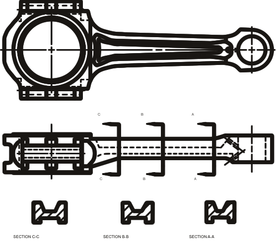
21 Section Views Types Removed section Removed sections are used to show the contours of complicated shapes such as wing and fuselage, blades for jet engines. Re moved sections are made in a manner similar to revolved sections, by passing an imaginary cutting plane perpendicular to a part then revolving the cross section 90 degrees. However, the cross section is then drawn adjacent to the orthographic view, not on it. If a number of removed sections are done on a part, cutting plane lines may be drawn with labels to clarify the position from which each section is taken. Whenever possible, a removed section should be on the same sheet as the part it represents, and it should be clearly labeled.
22
23
24 Section Views Types Offset Sections An offset section has its cutting plane bent at 90 degree angles to pass through important features. Offset sections are used for complex parts that have a number of important features that cannot be sectioned using a straight cutting plane. The cutting plane is bent at 90 degrees to pass through the hole, then bent 90 degrees again to pass through the slot.
25

26 Section Views Types Assembly section Auxiliary section
27
28 Section Views Types Special Sectioning Convections Ribs, Web and Thin features
29
30
31 Section Views Types Special Sectioning Convections Aligned sections are special types of orthographic drawings used to revolve or align special features of parts to clarify or make them easier to represent in section. Normally the alignment is along a horizontal or vertical center line and always less than 90 degrees.
32
33
34 Section Views Types Special Sectioning Convections Conventional breaks Conventional breaks are used in revolved section views or to shorten a view of an elongated part, such as the handle of a shovel or an axle of a vehicle.
Technical Drawing. MEC1000 Spring 2006 Instructor: David Anderson
 Technical Drawing MEC1000 Spring 2006 Instructor: David Anderson Topics Drawing Views Drawing Standards Best Practices Creating Drawings in SolidWorks Spring 2006 MEC1000 Technical Drawing - D. Anderson
Creating Sectional Views. This week you will learn creating sectional views. The steps to follow are: Cutting Plane Types of sectional views
 This week you will learn creating sectional views. The steps to follow are: Cutting Plane Types of sectional views Hatching (full, half, detailed etc) Assembly Sections Creating Section Views in CADD 1
Traditional Drawing Tools
 Engineering Drawing Traditional Drawing Tools DRAWING TOOLS DRAWING TOOLS 1. T-Square 2. Triangles DRAWING TOOLS HB for thick line 2H for thin line 3. Adhesive Tape 4. Pencils DRAWING TOOLS 5. Sandpaper
Freehand Sketching. Sections
 3 Freehand Sketching Sections 3.1 Why Freehand Sketches? 3.2 Freehand Sketching Fundamentals 3.3 Basic Freehand Sketching 3.4 Advanced Freehand Sketching Key Terms Objectives Explain why freehand sketching
DWG 001. Blueprint Reading. Line Standards Drawing Symbols. Instructor Guide
 DWG 001 Blueprint Reading Line Standards Drawing Symbols Instructor Guide Module Purpose Introduction The purpose of the Blueprint Reading modules is to introduce students to production drawings and blueprint
Technical Drawing Specifications Resource A guide to support VCE Visual Communication Design study design 2013-17
 A guide to support VCE Visual Communication Design study design 2013-17 1 Contents INTRODUCTION The Australian Standards (AS) Key knowledge and skills THREE-DIMENSIONAL DRAWING PARALINE DRAWING Isometric
West Sound Technical Skills Center 101 National Avenue N. Bremerton WA 98312
 West Sound Technical Skills Center 101 National Avenue N. Bremerton WA 98312 Instructor: Tony Sharpe Phone: 360-473-0585 Fax: 360-478-5090 Email: [email protected] Hours: 7:30 a.m. 3:00
OD1641 PRINCIPLES OF DRAFTING AND SHOP DRAWINGS
 SUBCOURSE OD1641 EDITION 8 PRINCIPLES OF DRAFTING AND SHOP DRAWINGS US ARMY REPAIR SHOP TECHNICIAN WARRANT OFFICER ADVANCED CORRESPONDENCE COURSE MOS/SKILL LEVEL: 441A PRINCIPLES OF DRAFTING AND SHOP
ME 111: Engineering Drawing
 ME 111: Engineering Drawing Lecture # 14 (10/10/2011) Development of Surfaces http://www.iitg.ernet.in/arindam.dey/me111.htm http://www.iitg.ernet.in/rkbc/me111.htm http://shilloi.iitg.ernet.in/~psr/ Indian
Standards for Working Drawings
 Standards for Working Drawings 27 August 2013 Department of Mechanical and Mechatronic Engineering and Sustainable Manufacturing California State University, Chico Chico, California 95929-0789 Contents
Roof Tutorial. Chapter 3:
 Chapter 3: Roof Tutorial The majority of Roof Tutorial describes some common roof styles that can be created using settings in the Wall Specification dialog and can be completed independent of the other
Introduction to Autodesk Inventor for F1 in Schools
 Introduction to Autodesk Inventor for F1 in Schools F1 in Schools Race Car In this course you will be introduced to Autodesk Inventor, which is the centerpiece of Autodesk s digital prototyping strategy
SAMPLE TEST PAPER - I
 SCHEME E SAMPLE TEST PAPER - I Course Name : Mechanical Engineering Group Course Code : AE/PG/PT/ME/MH/FE Semester : Third Subject : Mechanical Engineering Drawing 12042 Time : 90 Minutes Marks: 25 Instruction:
Introduction to Autodesk Inventor for F1 in Schools
 F1 in Schools race car Introduction to Autodesk Inventor for F1 in Schools In this course you will be introduced to Autodesk Inventor, which is the centerpiece of Autodesk s Digital Prototyping strategy
Wallingford Public Schools - HIGH SCHOOL COURSE OUTLINE
 Wallingford Public Schools - HIGH SCHOOL COURSE OUTLINE Course Title: Computer Aided Drafting & Design Course Number: 7163 Department: Career and Technical Education Grade(s): 9-12 Level(s): Academic Credit:
TECHNICAL DRAWING (67)
") TECHNICAL DRAWING (67) (Candidates offering Technical Drawing Applications are not eligible to offer Technical Drawing.) Aims: 1. To develop competence among the students to pursue technical courses like
TECHNICAL DRAWING (67) (Candidates offering Technical Drawing Applications are not eligible to offer Technical Drawing.) Aims: 1. To develop competence among the students to pursue technical courses like
Optical Illusions Essay Angela Wall EMAT 6690
 Optical Illusions Essay Angela Wall EMAT 6690! Optical illusions are images that are visually perceived differently than how they actually appear in reality. These images can be very entertaining, but
Modeling Curved Surfaces
 Modeling Cylindrical and Curved Theory Views of Cylinders Contour Lines Extruded Surfaces Revolved Surfaces & Cutouts Profile Shape Axis of Revolution Swept Surfaces & Cutouts Profile Shape Path Curves
Lesson 29: Lenses. Double Concave. Double Convex. Planoconcave. Planoconvex. Convex meniscus. Concave meniscus
 Lesson 29: Lenses Remembering the basics of mirrors puts you half ways towards fully understanding lenses as well. The same sort of rules apply, just with a few modifications. Keep in mind that for an
Technical Drawing. Dr. Anwar Abu-Zarifa. Dr. Anwar Abu-Zarifa. Islamic University Gaza. Industrial Engineering Department 1
 Technical Drawing الرسم الھندسي Dr. Anwar Abu-Zarifa Dr. Anwar Abu-Zarifa. Islamic University Gaza. Industrial Engineering Department 1 Office: IT Building,Room: I413 OfficeHrs: 12:00 13:00(So,Tue,We)
Micro. Pitts Special for the RFFS-100 by Chris O Riley
 Micro Pitts Special for the RFFS-100 by Chris O Riley F1 F2 F3 F4 1 2 3 4 All wood 1/32 inch sheet unless otherwise stated. F1 F2 F3 F4 Small balsa blocks for LG reinforcement Small balsa blocks for LG
CATIA Drafting TABLE OF CONTENTS
 TABLE OF CONTENTS Introduction...1 Drafting...2 Drawing Screen...3 Pull-down Menus...4 File...4 Edit...5 View...6 Insert...7 Tools...8 Drafting Workbench...9 Views and Sheets...9 Dimensions and Annotations...10
Activity 7.4 Assembly Models
 Page 1 of 7 Activity 7.4 Assembly Models Introduction Have you ever pieced together a jigsaw puzzle? The individual puzzle pieces have to be rotated and sometimes flipped around. A piece that makes up
Roof Tutorial. Chapter 3:
 Chapter 3: Roof Tutorial The first portion of this tutorial can be completed independent of the previous tutorials. We ll go over some common roof styles that can be created using settings in the Wall
Be visual all the time, and be verbal when labeling because explanations help clarify ideas.
 Great visual thinkers throughout history have kept records of their ideas in one form or another. (Leonardo da Vinci s sketchbooks are world famous.) Idea logs are an integral part of visual thinking and
Pro/ENGINEER Wildfire 4.0 Basic Design
 Introduction Datum features are non-solid features used during the construction of other features. The most common datum features include planes, axes, coordinate systems, and curves. Datum features do
An introduction to 3D draughting & solid modelling using AutoCAD
 An introduction to 3D draughting & solid modelling using AutoCAD Faculty of Technology University of Plymouth Drake Circus Plymouth PL4 8AA These notes are to be used in conjunction with the AutoCAD software
12-1 Representations of Three-Dimensional Figures
 Connect the dots on the isometric dot paper to represent the edges of the solid. Shade the tops of 12-1 Representations of Three-Dimensional Figures Use isometric dot paper to sketch each prism. 1. triangular
SolidWorks Implementation Guides. Sketching Concepts
 SolidWorks Implementation Guides Sketching Concepts Sketching in SolidWorks is the basis for creating features. Features are the basis for creating parts, which can be put together into assemblies. Sketch
USING MODELS TO TEACH AND LEARN ENGINEERING
 USING MODELS TO TEACH AND LEARN ENGINEERING Slobodan Urdarevik Western Michigan University ABSTRACT One of the biggest problems engineering students are facing is visualization. In fact, visualization
F1 in Schools - 2015 World Finals Technical Regulations
 2013 - F1 in Schools Ltd. Page 1 of 24 25 March 2015 Front Cover Colossus F1 2014 World Champions F1 Car, Robert May's School, Hampshire, England Amendments made on [Date] are indicated thus (using red
Selecting the Best Approach to Teach 3D Modeling to Technical College Engineering
 Paper ID #12358 Selecting the Best Approach to Teach 3D Modeling to Technical College Engineering Students Dr. Farzin Heidari, Texas A&M University, Kingsville c American Society for Engineering Education,
Understand the Sketcher workbench of CATIA V5.
 Chapter 1 Drawing Sketches in Learning Objectives the Sketcher Workbench-I After completing this chapter you will be able to: Understand the Sketcher workbench of CATIA V5. Start a new file in the Part
TABLE OF CONTENTS. INTRODUCTION... 5 Advance Concrete... 5 Where to find information?... 6 INSTALLATION... 7 STARTING ADVANCE CONCRETE...
 Starting Guide TABLE OF CONTENTS INTRODUCTION... 5 Advance Concrete... 5 Where to find information?... 6 INSTALLATION... 7 STARTING ADVANCE CONCRETE... 7 ADVANCE CONCRETE USER INTERFACE... 7 Other important
Dip is the vertical angle perpendicular to strike between the imaginary horizontal plane and the inclined planar geological feature.
 Geological Visualization Tools and Structural Geology Geologists use several visualization tools to understand rock outcrop relationships, regional patterns and subsurface geology in 3D and 4D. Geological
F1 in Schools - 2015 World Finals Technical Regulations. Formula 1 Class
 F1 in Schools - 2015 World Finals Technical Regulations Formula 1 Class 2013 - F1 in Schools Ltd. Page 1 of 23 7 July 2015 Front Cover Colossus F1 2014 World Champions F1 Car, Robert May's School, Hampshire,
Technical Regulations 2015-2016
 F1 in Schools - 2014 World Finals Technical Regulations Technical Regulations 2015-2016 2013 - F1 in Schools Ltd. Page 1 of 27 3 September 2015 CONTENTS PREFACE SUMMARY OF MAIN REVISIONS FROM 2013 REGULATIONS...
Pro/ENGINEER Wildfire 5.0 Introduction to Surface Modeling
 Introduction Several advanced surface types are available as listed below. Variable Section Sweep Boundary Blend Section to Surfaces Blend Surface to Surface Blend A surface is created by sweeping a single
COMPLIMENTARY WOODWORKING PLAN
 COMPLIMENTARY WOODWORKING PLAN Adirondack Chair This downloadable plan is copyrighted. Please do not share or redistribute this plan in any way. It has been created for Wilton Tools, a division of WMH
F1 in Schools - 2014 World Finals Technical Regulations. 2014 WORLD FINALS Technical Regulations
 2014 WORLD FINALS Technical Regulations Refer also to the 2014 World Finals Competition Regulations. For World Finals use only. 2013 - F1 in Schools Ltd. Page 1 of 23 13 August 2014 Front Cover A1 Racing
Creating detailed drawings
 Creating detailed drawings Publication Number spse01545 Creating detailed drawings Publication Number spse01545 Proprietary and restricted rights notice This software and related documentation are proprietary
720 Contour Grading. General. References. Resources. Definitions
 720 Contour Grading General Contour grading directs water to a desired point, prevents erosion, provides noise deflection, provides visual fit of the facility into the landscape, and protects desirable
Introduction to CATIA V5
 Introduction to CATIA V5 Release 16 (A Hands-On Tutorial Approach) Kirstie Plantenberg University of Detroit Mercy SDC PUBLICATIONS Schroff Development Corporation www.schroff.com www.schroff-europe.com
Creating 2D Drawings from 3D AutoCAD Models
 Creating 2D Drawings from 3D AutoCAD Models David Piggott CrWare, LP GD205-2P This class explores the various techniques in creating 2D part and assembly drawings from 3D AutoCAD models. As part of the
MET 306. Activity 8a. Mechanism Design Creo 2.0 Level 7 POINT A GROUND LINK LINK 1 LINK 2 LINK 3 POINT B 10/15/2010 1
 Mechanism Design Creo 2.0 Level 7 POINT A LINK 1 GROUND LINK LINK 2 LINK 3 POINT B 10/15/2010 1 Download parts ground, key, link_1, link_2, link_3 and pulley from the V:/MET_306/Activity_8_Creo drive.
RESEARCH PAPERS FACULTY OF MATERIALS SCIENCE AND TECHNOLOGY IN TRNAVA SLOVAK UNIVERSITY OF TECHNOLOGY IN BRATISLAVA
 RESEARCH PAPERS FACULTY OF MATERIALS SCIENCE AND TECHNOLOGY IN TRNAVA SLOVAK UNIVERSITY OF TECHNOLOGY IN BRATISLAVA 2010 Number 29 3D MODEL GENERATION FROM THE ENGINEERING DRAWING Jozef VASKÝ, Michal ELIÁŠ,
Sheet Metal Bending. By- Prem Mahendranathan
 Sheet Metal Bending By- BENDING n Bending is a manufacturing process by which a metal can be deformed by plastically deforming the material and changing its shape n Deformation about one axis PROFILES
Creating Drawings in Pro/ENGINEER
 6 Creating Drawings in Pro/ENGINEER This chapter shows you how to bring the cell phone models and the assembly you ve created into the Pro/ENGINEER Drawing mode to create a drawing. A mechanical drawing
AIDT STUDENT TRAINING MANUAL TABLE OF CONTENTS
 AIDT STUDENT TRAINING MANUAL TABLE OF CONTENTS I. BLUEPRINT READING...1 A. ALPHABET OF LINES...1 Figure 1-1 Alphabet of Lines...2 Figure 1-2 Examples of Line Types...3 1. Object Lines...3 Figure 1-3 Object
Building an Off-Center Fixture for Turning Pendants
 Building an Off-Center Fixture for Turning Pendants Turning a pendant off-center with most available metal pendant chucks means that you will have a significant amount of mass off center, which will limit
An Application of Analytic Geometry to Designing Machine Parts--and Dresses
 Electronic Proceedings of Undergraduate Mathematics Day, Vol. 3 (008), No. 5 An Application of Analytic Geometry to Designing Machine Parts--and Dresses Karl Hess Sinclair Community College Dayton, OH
Get The Picture: Visualizing Financial Data part 1
 Get The Picture: Visualizing Financial Data part 1 by Jeremy Walton Turning numbers into pictures is usually the easiest way of finding out what they mean. We're all familiar with the display of for example
Chapter 9. Editing Features. Learning Objectives
 Chapter 9 Editing Features Learning Objectives After completing this chapter, you will be able to: Edit features. Edit sketches of the sketch based features. Edit the sketch plane of the sketch based features.
Chapter 22: Electric Flux and Gauss s Law
 22.1 ntroduction We have seen in chapter 21 that determining the electric field of a continuous charge distribution can become very complicated for some charge distributions. t would be desirable if we
Basic Problem: Map a 3D object to a 2D display surface. Analogy - Taking a snapshot with a camera
 3D Viewing Basic Problem: Map a 3D object to a 2D display surface Analogy - Taking a snapshot with a camera Synthetic camera virtual camera we can move to any location & orient in any way then create a
F B = ilbsin(f), L x B because we take current i to be a positive quantity. The force FB. L and. B as shown in the Figure below.
, L x B because we take current i to be a positive quantity. The force FB. L and. B as shown in the Figure below.") PHYSICS 176 UNIVERSITY PHYSICS LAB II Experiment 9 Magnetic Force on a Current Carrying Wire Equipment: Supplies: Unit. Electronic balance, Power supply, Ammeter, Lab stand Current Loop PC Boards, Magnet
PHYSICS 176 UNIVERSITY PHYSICS LAB II Experiment 9 Magnetic Force on a Current Carrying Wire Equipment: Supplies: Unit. Electronic balance, Power supply, Ammeter, Lab stand Current Loop PC Boards, Magnet
Copyright 2008 OLYMPUS CORPORATION All Rights Reserved. Paper Craft Assembly Manual
 Paper Craft Assembly Manual Before assembly: 1/9 Tips on assembly: Print all the parts (Photo-quality paper is recommended for ink-jet printers and paper of medium thickness (0.20 mm) for laser printers.)
SolidWorks Tutorial 4 CANDLESTICK
 SolidWorks Tutorial 4 CANDLESTICK Candlestick In this tutorial you will make a simple container and a candlestick out of sheetmetal. You will learn about working with sheet metal in SolidWorks. We will
Map Patterns and Finding the Strike and Dip from a Mapped Outcrop of a Planar Surface
 Map Patterns and Finding the Strike and Dip from a Mapped Outcrop of a Planar Surface Topographic maps represent the complex curves of earth s surface with contour lines that represent the intersection
Safe & Sound Bridge Terminology
 Safe & Sound Bridge Terminology Abutment A retaining wall supporting the ends of a bridge, and, in general, retaining or supporting the approach embankment. Approach The part of the bridge that carries
Kankakee Community College
 Kankakee Community College Course prefix and number: DRFT 2134 Course title: AutoCAD III Semester: Fall 2014 Credit hours: 4 Lecture hours: 2.5 Lab hours: 3 Catalog description: Prerequisite: DRFT 2114,
Course Description. Spring 2004 1
 Spring 2004 1 Course Description AE4375: advanced treatment for undergrads; focus on learning and aplying CAD to engineering; CAD modeling projects. AE6380: graduate course on CAD focusing on how tools
Reflection and Refraction
 Equipment Reflection and Refraction Acrylic block set, plane-concave-convex universal mirror, cork board, cork board stand, pins, flashlight, protractor, ruler, mirror worksheet, rectangular block worksheet,
30a. 31a. 30b 12. 31b. 29a 28a 1/48SCALEHEMSDAUPHIN PAGE2/10
 9 11 10 43 42 49 50 32 7 51 52 48 58 5 6 8 59 2 3 4 1 24 30a 31a 30 30b 12 31b 31 28 13 29 29a 28a 1/48SCALEHEMSDAUPHIN PAGE2/10 38 82 38f 85 84 86 83 37d 35 38a 37 60 17 21 20 16 15 87 27 34 40c 36b 36a
Structural Integrity Analysis
 Structural Integrity Analysis 1. STRESS CONCENTRATION Igor Kokcharov 1.1 STRESSES AND CONCENTRATORS 1.1.1 Stress An applied external force F causes inner forces in the carrying structure. Inner forces
Self-Portrait Steps Images taken from Andrew Loomis Drawing Head & Hands (there are many sites to download this out of print book for free)
") Self-Portrait Steps Images taken from Andrew Loomis Drawing Head & Hands (there are many sites to download this out of print book for free) First of all- put the idea of it doesn t look like me! out of
Self-Portrait Steps Images taken from Andrew Loomis Drawing Head & Hands (there are many sites to download this out of print book for free) First of all- put the idea of it doesn t look like me! out of
rarecorvettes.com, [email protected], (831) 475-4442 Pacific Time Zone
 475-4442 Pacific Time Zone") INTRODUCTION TO WHEEL ALIGNMENT A SHORT COURSE ON WHEEL ALIGNMENT, FRONT AND REAR PREPARED FOR THE N.C.R.S. NATIONAL CONVENTION JUNE 29 TO JULY 5, 2012 by: JOE CALCAGNO, RARE CORVETTES rarecorvettes.com,
INTRODUCTION TO WHEEL ALIGNMENT A SHORT COURSE ON WHEEL ALIGNMENT, FRONT AND REAR PREPARED FOR THE N.C.R.S. NATIONAL CONVENTION JUNE 29 TO JULY 5, 2012 by: JOE CALCAGNO, RARE CORVETTES rarecorvettes.com,
Universal Gauge Measuring System USERS MANUAL
 Universal Gauge Measuring System 2002 Chief Automotive Technologies, Inc. Chief s Limited One-Year Warranty & Liability CHIEF'S LIMITED ONE-YEAR WARRANTY & LIABILITY Chief Automotive Technologies, Inc.
Projectile Motion 1:Horizontally Launched Projectiles
 A cannon shoots a clown directly upward with a speed of 20 m/s. What height will the clown reach? How much time will the clown spend in the air? Projectile Motion 1:Horizontally Launched Projectiles Two
The purposes of this experiment are to test Faraday's Law qualitatively and to test Lenz's Law.
 260 17-1 I. THEORY EXPERIMENT 17 QUALITATIVE STUDY OF INDUCED EMF Along the extended central axis of a bar magnet, the magnetic field vector B r, on the side nearer the North pole, points away from this
Isometric Axes: The lines AB, AD and AE meeting at a point A and making an angle of 120 o with each other are termed isometric axes
 ISOMTRI PROJTION When a solid is resting in its simple position, the front or top view, taken separately, gives an incomplete idea of the form of the object. When the solid is tilted from its simple position
Microsoft Excel 2010 Charts and Graphs
 Microsoft Excel 2010 Charts and Graphs Email: [email protected] Web Page: http://training.health.ufl.edu Microsoft Excel 2010: Charts and Graphs 2.0 hours Topics include data groupings; creating
DRAWING INSTRUMENTS AND THEIR USES
 Chapter - A DRAWING INSTRUMENTS AND THEIR USES Drawing Instruments are used to prepare neat and accurate Drawings. To a greater extent, the accuracy of the Drawings depend on the quality of instruments
Geometry 1. Unit 3: Perpendicular and Parallel Lines
 Geometry 1 Unit 3: Perpendicular and Parallel Lines Geometry 1 Unit 3 3.1 Lines and Angles Lines and Angles Parallel Lines Parallel lines are lines that are coplanar and do not intersect. Some examples
Bedford, Fowler: Statics. Chapter 4: System of Forces and Moments, Examples via TK Solver
 System of Forces and Moments Introduction The moment vector of a force vector,, with respect to a point has a magnitude equal to the product of the force magnitude, F, and the perpendicular distance from
Solid Edge structural frames and weldments
 Solid Edge structural frames and weldments White Paper Intelligent, process-specific applications that speed time to manufacturing. White Paper Solid Edge structural frames and weldments 2 Contents Solid
How to read Plans and Do Basic Drawings
 How to read Plans and Do Basic Drawings Workshop session W1 10.00 Site Orientation Exercise 10.10 Drawing Conventions 10.45 Can drawings Distort the Truth? 11.30 Summary + Coffee 11.45 Simple Drawing Techniques
Shaping Space DRAWING GUIDELINES
 DRAWING GUIDELINES Types of drawin Freehand drawings, paintings or sketches These are good for recording the general visual effect of a building or for making personal statements about how you feel about
Structural Axial, Shear and Bending Moments
 Structural Axial, Shear and Bending Moments Positive Internal Forces Acting Recall from mechanics of materials that the internal forces P (generic axial), V (shear) and M (moment) represent resultants
LABORATORY TWO GEOLOGIC STRUCTURES
 EARTH AND ENVIRONMENT THROUGH TIME LABORATORY- EES 1005 LABORATORY TWO GEOLOGIC STRUCTURES Introduction Structural geology is the study of the ways in which rocks or sediments are arranged and deformed
IN00419 (rev A) Aqua 6 Glide Quadrant and Off-set Quadrant Enclosure
 Aqua 6 Glide Quadrant and Off-set Quadrant Enclosure") IN00419 (rev A) Aqua 6 Glide Quadrant and Off-set Quadrant Enclosure Instruction suitable for both Quadrant & Off-set Quadrant variations. Instruction suitable for both Right and Left Hand fixing variations
IN00419 (rev A) Aqua 6 Glide Quadrant and Off-set Quadrant Enclosure Instruction suitable for both Quadrant & Off-set Quadrant variations. Instruction suitable for both Right and Left Hand fixing variations
Cycles in the Sky. Teacher Guide: Cycles in the Sky Page 1 of 8 2008 Discovery Communications, LLC
 Cycles in the Sky What is a Fun damental? Each Fun damental is designed to introduce your younger students to some of the basic ideas about one particular area of science. The activities in the Fun damental
Sheet Metal Stamping Dies & Processes
 Training Objectives After watching the program and reviewing this printed material, the viewer will gain knowledge and understanding of the stamping process and the die systems used to form sheet metal.
FREEBIRD THE ORIGINAL D.I.Y. ORNITHOPTER! Tools and Glue. Required Materials
 Do not try to make your ornithopter using "household materials". If you want it to fly, you have to build it right. FREEBIRD THE ORIGINAL D.I.Y. ORNITHOPTER! Wingspan: 16 inches Weight: 1/4 ounce The Ornithopter
SpaceClaim Introduction Training Session. A SpaceClaim Support Document
 SpaceClaim Introduction Training Session A SpaceClaim Support Document In this class we will walk through the basic tools used to create and modify models in SpaceClaim. Introduction We will focus on:
Weekend Cabin Retreat Project Site Plans
 Weekend Cabin Retreat Project Site Plans Sacramento City College EDT 300/ENGR 306 EDT 300/ENGR 306 - Site Plans 1 Cabin Project Site Plan/Bubble Diagram - Assignment 1 =10-0 Floor Plan - Assignment 1/4
Roof Rehab (Roof truss) Classroom Activity
 Classroom Activity") Roof Rehab (Roof truss) Classroom Activity The Classroom Activity introduces students to the context of a performance task, so they are not disadvantaged in demonstrating the skills the task intends to
Roof Rehab (Roof truss) Classroom Activity The Classroom Activity introduces students to the context of a performance task, so they are not disadvantaged in demonstrating the skills the task intends to
Holes & Selective Laser Sintering
 SLS is one of the most accurate 3D printing processes. The process has a layer thickness of 0.1mm. This is the thickness with which a new layer is added to each part. In any direction therefore the maximum
CHAPTER 3 Drafting Conventions
 CHAPTER 3 Drafting Conventions OBJECTIVE This chapter discusses line types, symbols, letters, and notes found on architectural drawings. KEY TERMS border lines hidden object lines note center line ID label
Assignment 1: Sketching and Simple Models
 Assignment 1: Sketching and Simple Models 24 370, Engineering Design I, Spring 2011 Due @ 12:30, Wednesday January 19 th 2011 Name: Part 1: Conceptualization Sketches C Clamp Cam Shaft 1.a: Studies in
Section. Tolerances. Aluminum Extrusion Manual. 4th Edition
 Section 8 Tolerances Aluminum Extrusion Manual 4th Edition Section 8 How straight is straight enough? How flat is flat enough? How uniform must a wall thickness be in order to be acceptable? These are
Optical Digitizing by ATOS for Press Parts and Tools
 Optical Digitizing by ATOS for Press Parts and Tools Konstantin Galanulis, Carsten Reich, Jan Thesing, Detlef Winter GOM Gesellschaft für Optische Messtechnik mbh, Mittelweg 7, 38106 Braunschweig, Germany
House Design Tutorial
 Chapter 2: House Design Tutorial This House Design Tutorial shows you how to get started on a design project. The tutorials that follow continue with the same plan. When we are finished, we will have created
Classification of Malocclusion
 Classification of Malocclusion What s going on here? How would you describe this? Dr. Robert Gallois REFERENCE: Where Do We Begin? ESSENTIALS FOR ORTHODONTIC PRACTICE By Riolo and Avery Chapter 6 pages
Raising the Roof Creating Roofs in Revit David Cohn
 David Cohn AB322-1 Roofs are one of the most complex architectural elements to model, but with Revit you can create just about any type of roof. This class will explore the best methods for creating various
Basic Shapes. Most paintings can be broken down into basic shapes. See how this famous painting by Cézanne can be broken down into basic shapes.
 Basic Shapes Squares, rectangles, triangles, cones, cylinders, circles, ovals...these are the basic shapes that will aid you in drawing objects more accurately. This technique can be used when doing a
INSTALLATION PROCEDURES FOR PRINTED CIRCUIT BOARD TERMINATORS D-607-XX
 Page: 1 of 9 INSTALLATION PROCEDURES FOR PRINTED CIRCUIT BOARD TERMINATORS D-607-XX 1. SCOPE This engineering standard contains the termination procedures and inspection requirements for the printed circuit
GEOLOGIC MAPS. PURPOSE: To be able to understand, visualize, and analyze geologic maps
 GEOLOGIC MAPS PURPOSE: To be able to understand, visualize, and analyze geologic maps Geologic maps show the distribution of the various igneous, sedimentary, and metamorphic rocks at Earth s surface in