Programmable Logic Design Grzegorz Budzyń Lecture. 12: VHDL vs Verilog
|
|
|
- Eugenia Farmer
- 9 years ago
- Views:
Transcription

1 Programmable Logic Design Grzegorz Budzyń Lecture 12: VHDL vs Verilog

2 Plan Introduction Veriloginbrief VHDL/Verilog comparison Examples Summary

3 Introduction

4 Introduction At presenttherearetwo industry standard hardware description languages, VHDL and Verilog. The complexity of ASIC and FPGA designs has meant an increase in the number of specific tools and libraries of macro and mega cells written in either VHDL or Verilog. As a result, it is important that designers know both VHDL and Verilogand that EDA tools vendors provide tools that provide an environment allowing both languages to be used in unison.

5 Introduction VHDL (Very high speed integrated circuit Hardware Description Language) became IEEE standard 1076 in The Veriloghardware description language has been used far longer than VHDL and has been used extensively since it was launched by Gateway in Cadence bought Gateway in 1989 and opened Verilogto the public domain in Verilogbecame IEEE standard 1364 in December 1995

6 Verilog in brief

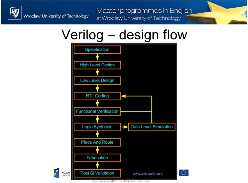
7 Verilog design flow
8 Verilog abstraction levels Verilog supports three main abstraction levels: Behaviorallevel asystem isdescribedby concurrent algorithm Register-transfer level a system ischaracterisedby by operations and transfer of data between registers according to an explicit clock Gatelevel a system isdescribedby logicallinksand their timing characteristics

9 Verilog Hello world

10 Verilog 8-bit counter example

11 Basic constructs

12 Verilog - hierarchy Verilog structures which build the hierarchy are: modules ports A module is the basic unit of the model, and it may be composed of instancesof other modules

; endmodule module bar (port1, port2);.")
13 Verilog - hierarchy the top level module is not instantiated by any other module Example: module foo; bar bee (port1, port2); endmodule module bar (port1, port2);... endmodule
; endmodule module bar (port1,")
14 Verilog Port typesinverilog: Input Output Inout Matching ports by names: foo f1 (.bidi(bus),.out1(sink1),.in1(source1)); versus normal way foof1 (source1,, sink1,, bus);
); versus normal way foof1")
15 Verilog - modules Verilogmodels are made up of modules Modules are made of different types of components: Parameters Nets Registers Primitives and Instances Continuous Assignments Procedural Blocks Task/Function definitions

16 Verilog - parameters Parametersare constants whose values are determined at compile-time They are defined with the parameter statement: parameter identifier = expression; Example: parameter width = 8, msb= 7, lsb= 0;

17 Verilog - nets Nets are the things that connect model components together like signals in VHDL Nets are declared in statements like this: net_type[range] [delay3] list_of_net_identifiers Example: wire w1, w2; tri [31:0] bus32;
![declared in statements like this: net_type[range]](/docs-images/46/21286919/images/page_17.jpg "[delay3] list_of_net_identifiers Example: wire w1, w2;")

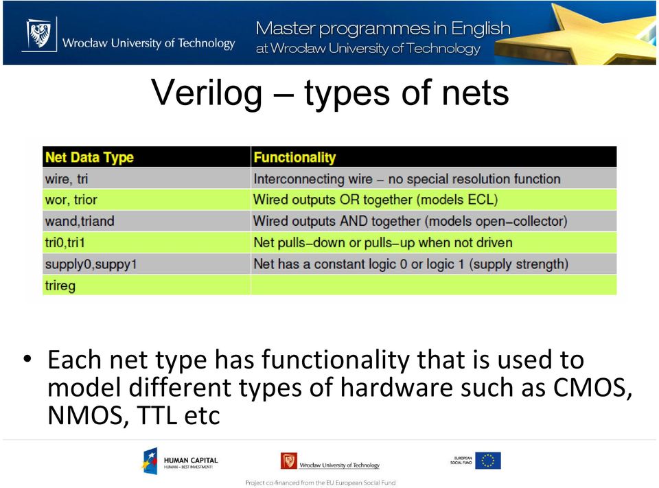
18 Verilog types of nets Eachnet typehasfunctionalitythatisusedto model differenttypesofhardware suchas CMOS, NMOS, TTL etc
19 Verilog net drivers Nets are driven by net drivers. Drivers may be: output port of a primitive instance output port of a module instance left-hand side of a continuous assignment There may be more than one driveron a net If there is more than one driver, the value of the net is determined by a built-inresolution function

20 Verilog - registers Registersare storage elements Values are stored in registers in procedural assignment statements Registers can be used as the source for a primitive or module instance (i.e. registers can be connected to input ports), but they cannot be driven in the same way a net can Examples: regr1, r2; reg[31:0] bus32; integer i;

21 Verilog - registers There are four types of registers: Reg: This is the generic register data type. A regdeclaration can specify registers which are 1 bit wide to 1 million bits wide Integer Integersare 32 bit signed values Time Registers declared with the timekeyword are 64-bit unsigned integers Real (and Realtime) Real registers are 64-bit IEEE floating point
22 Verilog - memories Verilogallows arrays of registers, called memories Memories are static, single-dimension arrays The format of a memory declaration is: reg[range] identifier range ; Example: reg[0:31] temp, mem[1:1024];... temp = mem[10]; --extract 10th element bit = temp[3]; --extarct3rd bit
23 Verilog - primitives Primitives are pre-defined module types The Verilogprimitives are sometimes called gates, because for the most part, they are simple logical primitives Examples: And, nand, or, nor, xor, xnor Buf, not Pullup, pulldown bufif0, notif0
24 Examples: Verilog - primitives module test; wire n1, n2; regain, bin; and and_prim(n1, ain, bin); not not_prim(n2, n1); endmodule
25 Procedural blocks
26 Verilog - Continuous assignments Continuous assignments are known as data flow statements They describe how data moves from one place, either a net or register, to another They are usually thought of as representing combinational logic Examples: assign w1 = w2 & w3; assign (strong1, pull0) mynet = enable;
27 Verilog - Procedural blocks Procedural blocks are the part of the language which represents sequential behavior A module can have as many procedural blocks as necessary These blocks are sequences of executable statements The statements in each block are executed sequentially, but the blocks themselves are concurrent and asynchronous to other blocks
28 Verilog - Procedural blocks There are two types of procedural blocks, initial blocks and always blocks All initial and always blocks contain a single statement, which may be a compound statement, e.g.: initial begin statement1 ; statement2 ;... end
29 Verilog - Initial blocks All initial blocks begin at time 0 and execute the initial statement Because the statement may be a compound statement, this may entail executing lots of statements An initial block may cause activity to occur throughout the entire simulation of the model When the initial statement finishes execution, the initial block terminates
30 Verilog - Initial blocks Examples: initial x = 0; // a simple initialization initial begin x = 1; // an initialization y = f(x); #1x = 0; // a value change 1 time unit later y = f(x); end
31 Verilog Always block Always blocks also begin at time 0 The only difference between an always block and an initial block is that when the always statement finishes execution, it starts executing again
32 Tasks and functions
33 Verilog Tasks/functions Tasks and functions are declared within modules Tasks may only be used in procedural blocks A task invocationis a statement by itself. It may not be used as an operand in an expression Functions are used as operands in expressions A function may be used in either a procedural block or a continuous assignment, or indeed, any place where an expression may appear
34 Verilog Tasks Tasks may have zero or more arguments, and they may be input, output, or inout arguments Time can elapse during the execution of a task, according to time and event controls in the task definition Exmaple: task do_read; begin adbus_reg= addr; // put address out end endtask
35 Verilog Functions In contrast to tasks, functions must execute in a single instant of simulated time That is, not time or delay controls are allowed in a function Function arguments are also restricted to inputs only. Output and inoutarguments are not allowed. The output of a function is indicated by an assignment to the function name
36 Verilog Functions Example: function [15:0] relocate; input [11:0] addr; input [3:0] relocation_factor; begin relocate = addr+ (relocation_factor<<12); count = count+ 1; // how many have we done end endfunction assign absolute_address= relocate(relative_address, rf);
37 VHDL/Verilog comparison
38 Capability VHDL like Pascal or Ada programming languages Verilog like C programming language Itisimportantto rememberthatbothare Hardware DescriptionLanguagesandnot programming languages For synthesisonlya subsetoflanguagesisused
39 Capability Hardware structure can be modeled equally effectively in both VHDL and Verilog. When modeling abstract hardware, the capability of VHDL can sometimes only be achieved in Verilogwhen using the PLI. The choice of which to use is not therefore based solely on technical capability but on: personal preferences EDA tool availability commercial, business and marketing issues
40 Capability The modeling constructs of VHDL and Verilog cover a slightly different spectrum across the levels of behavioral abstraction Source: [1]
41 Compilation VHDL: Multiple design-units (entity/architecture pairs), that reside in the same system file, may be separately compiled if so desired. It is good design practice to keep each design unit in it's own system file in which case separate compilation should not be an issue.
42 Compilation Verilog: The Veriloglanguage is still rooted in it's native interpretative mode. Compilation is a means of speeding up simulation, but has not changed the original nature of the language. Thecare must be taken with both the compilation order of code written in a single file and the compilation order of multiple files. Simulation results can change by simply changing the order of compilation.
43 Data types VHDL: A multitude of language or user defined data types can be used. This may mean dedicated conversion functions are needed to convert objects from one type to another. The choice of which data types to use should be considered wisely, especially enumerated (abstract) data types. VHDL may be preferred because it allows a multitude of language or user defined data types to be used.
44 Data types Verilog: Compared to VHDL, Verilogdata types a very simple, easy to use and very much geared towards modeling hardware structure as opposed to abstract hardware modeling. Unlike VHDL, all data types used in a Verilogmodel are defined by the Veriloglanguage and not by the user. There are net data types, for example wire, and a register data type called reg. A model with a signal whose type is one of the net data types has a corresponding electrical wire in the implied modeled circuit. Verilogmay be preferred because of it's simplicity.
45 Design reusability VHDL: Procedures and functions may be placed in a package so that they are available to any design-unit that wishes to use them Verilog: There is no concept of packages in Verilog. Functions and procedures used within a model must be defined in the module. To make functions and procedures generally accessible from different module statements the functions and procedures must be placed in a separate system file and included using the `include compiler directive.
46 Ease of learning Starting with zero knowledge of either language, Verilogis probably the easiest to grasp and understand. VHDL may seem less intuitive at first for two primary reasons: First, it is very strongly typed; a feature that makes it robust and powerful for the advanced user after a longer learning phase. Second, there are many ways to model the same circuit, specially those with large hierarchical structures
47 High level constructs VHDL: There are more constructs and features for high-level modeling in VHDL than there are in Verilog. Abstract data types can be used along with the following statements: package statements for model reuse, configuration statements for configuring design structure, generate statements for replicating structure, generic statements for generic models that can be individually characterized, for example, bit width. All these language statements are useful in synthesizable models.
48 High level constructs Verilog: Except for being able to parameterize models by overloading parameter constants, there is no equivalent to the high-level VHDL modeling statements in Verilog
49 Libraries VHDL: A library is a store for compiled entities, architectures, packages and configurations. Useful for managing multiple design projects. Verilog: There is no concept of a library in Verilog. This is due to it's origins as an interpretive language.
50 Low level constructs VHDL: Simple two input logical operators are built into the language, they are: NOT, AND, OR, NAND, NOR, XOR and XNOR. Any timing must be separately specified using the after clause. Separate constructs defined under the VITAL language must be used to define the cell primitives of ASIC and FPGA libraries.
51 Low level constructs Verilog: The Veriloglanguage was originally developed with gate level modeling in mind, and so has very good constructs for modeling at this level and for modeling the cell primitives of ASIC and FPGA libraries. Examples include User Defined Primitives (UDP), truth tables and the specify block for specifying timing delays across a module.
52 Managing large designs VHDL: Configuration, generate, generic and package statements all help manage large design structures. Verilog: There are no statements in Verilogthat help manage large designs
53 Operators The majority of operators are the same between the two languages. Verilogdoes have very useful unary reduction operators that are not in VHDL. A loop statement can be used in VHDL to perform the same operation as a Verilogunary reduction operator. VHDL has the mod operator that is not found in Verilog.
54 Procedures and tasks VHDL: concurrent procedure calls are allowed Verilog: concurrent procedure calls are not allowed
55 Readability This is more a matter of coding style and experience than language feature. VHDL is a concise and verbose language; Verilogis more like C because it's constructs are based approximately 50% on C and 50% on Ada. For this reason an existing C programmer may prefer Verilogover VHDL. Whatever HDL is used, when writing or reading an HDL model to be synthesized it is important to think about hardware intent.
56 Structural replication VHDL: The generate statement replicates a number of instances of the same design-unit or some sub part of a design, and connects it appropriately. Verilog: There is no equivalent to the generate statement in Verilog.
57 Verboseness VHDL: Because VHDL is a very strongly typed language models must be coded precisely with defined and matching data types. This may be considered an advantage or disadvantage. It does mean models are often more verbose, and the code often longer, than it's Verilogequivalent.
58 Verboseness Verilog: Signals representing objects of different bits widths may be assigned to each other. The signal representing the smaller number of bits is automatically padded out to that of the larger number of bits, and is independent of whether it is the assigned signal or not. Unused bits will be automatically optimized away during the synthesis process. This has the advantage of not needing to model quite so explicitly as in VHDL, but does mean unintended modeling errors will not be identified by an analyzer.
59 Examples
60 VHDL: Binary up counter process (clock) begin if clock='1' and clock'event then counter <= counter + 1; end if; end process;
61 Verilog: Binary up counter reg [upper:0] counter; clock) counter <= counter + 1;
62 VHDL: D FilpFlop process (<clock>) begin if <clock>'event and <clock>='1' then <output> <= <input>; end if; end process;
63 Verilog: D FilpFlop <clock>) begin <reg> <= <signal>; end
64 VHDL: Synchronous multiplier process (<clock>) begin if <clock>='1' and <clock>'event then <output> <= <input1> * <input2>; end if; end process;
65 Verilog: Synchronous multiplier wire [17:0] <a_input>; wire [17:0] <b_input>; reg [35:0] <product>; <clock>) <product> <= <a_input> * <b_input>;
66 Summary
67 Strong typing User-defined types Dynamic memory allocation Physical types Enumerated types Records/structs VHDL Yes Yes Yes Yes Yes Yes Verilog No No No No No No
68 Bit (vector) / integer equivalence Subprograms Separate packaging Gate level modeling VHDL Partial (by libraries) Yes Yes Packages Yes VITAL Verilog Yes Yes Yes Include files Yes Builtin primitives
69 Conditional statements Yes VHDL If-then-else/elsif (priority) Case (mux) Selected assign (mux) Conditional assign (priority) No don t care matching capability Yes Verilog if-else (priority) case (mux) casex(mux)?: (conditional used in concurrent assignments)
70 Iteration VHDL Yes Loop while-loop for-loop exit next Verilog Yes repeat for while
71 Thank you for your attention
72 References [1] Douglas J. Smith, VHDL & VerilogCompared & Contrasted Plus Modeled Example Written in VHDL, Verilog and C [2] VerilogQuickRef.pdf [3] [4]
Life Cycle of a Memory Request. Ring Example: 2 requests for lock 17
 Life Cycle of a Memory Request (1) Use AQR or AQW to place address in AQ (2) If A[31]==0, check for hit in DCache Ring (3) Read Hit: place cache word in RQ; Write Hit: replace cache word with WQ RDDest/RDreturn
Finite State Machine Design and VHDL Coding Techniques
 Finite State Machine Design and VHDL Coding Techniques Iuliana CHIUCHISAN, Alin Dan POTORAC, Adrian GRAUR "Stefan cel Mare" University of Suceava str.universitatii nr.13, RO-720229 Suceava [email protected],
VHDL GUIDELINES FOR SYNTHESIS
 VHDL GUIDELINES FOR SYNTHESIS Claudio Talarico For internal use only 1/19 BASICS VHDL VHDL (Very high speed integrated circuit Hardware Description Language) is a hardware description language that allows
ECE 3401 Lecture 7. Concurrent Statements & Sequential Statements (Process)
") ECE 3401 Lecture 7 Concurrent Statements & Sequential Statements (Process) Concurrent Statements VHDL provides four different types of concurrent statements namely: Signal Assignment Statement Simple Assignment
ECE 3401 Lecture 7 Concurrent Statements & Sequential Statements (Process) Concurrent Statements VHDL provides four different types of concurrent statements namely: Signal Assignment Statement Simple Assignment
Modeling Sequential Elements with Verilog. Prof. Chien-Nan Liu TEL: 03-4227151 ext:34534 Email: [email protected]. Sequential Circuit
 Modeling Sequential Elements with Verilog Prof. Chien-Nan Liu TEL: 03-4227151 ext:34534 Email: [email protected] 4-1 Sequential Circuit Outputs are functions of inputs and present states of storage elements
Digital Circuit Design Using Xilinx ISE Tools
 Digital Circuit Design Using Xilinx ISE Tools Contents 1. Introduction... 1 2. Programmable Logic Device: FPGA... 2 3. Creating a New Project... 2 4. Synthesis and Implementation of the Design... 11 5.
ECE232: Hardware Organization and Design. Part 3: Verilog Tutorial. http://www.ecs.umass.edu/ece/ece232/ Basic Verilog
 ECE232: Hardware Organization and Design Part 3: Verilog Tutorial http://www.ecs.umass.edu/ece/ece232/ Basic Verilog module ();
Digital Systems Design! Lecture 1 - Introduction!!
 ECE 3401! Digital Systems Design! Lecture 1 - Introduction!! Course Basics Classes: Tu/Th 11-12:15, ITE 127 Instructor Mohammad Tehranipoor Office hours: T 1-2pm, or upon appointments @ ITE 441 Email:
A New Paradigm for Synchronous State Machine Design in Verilog
 A New Paradigm for Synchronous State Machine Design in Verilog Randy Nuss Copyright 1999 Idea Consulting Introduction Synchronous State Machines are one of the most common building blocks in modern digital
VHDL Test Bench Tutorial
 University of Pennsylvania Department of Electrical and Systems Engineering ESE171 - Digital Design Laboratory VHDL Test Bench Tutorial Purpose The goal of this tutorial is to demonstrate how to automate
A Verilog HDL Test Bench Primer Application Note
 A Verilog HDL Test Bench Primer Application Note Table of Contents Introduction...1 Overview...1 The Device Under Test (D.U.T.)...1 The Test Bench...1 Instantiations...2 Figure 1- DUT Instantiation...2
ETEC 2301 Programmable Logic Devices. Chapter 10 Counters. Shawnee State University Department of Industrial and Engineering Technologies
 ETEC 2301 Programmable Logic Devices Chapter 10 Counters Shawnee State University Department of Industrial and Engineering Technologies Copyright 2007 by Janna B. Gallaher Asynchronous Counter Operation
ECE 451 Verilog Exercises. Sept 14, 2007. James Barnes ([email protected])
") ECE 451 Verilog Exercises Sept 14, 2007 James Barnes ([email protected]) Organization These slides give a series of self-paced exercises. Read the specification of each exercise and write your
ECE 451 Verilog Exercises Sept 14, 2007 James Barnes ([email protected]) Organization These slides give a series of self-paced exercises. Read the specification of each exercise and write your
LAB #3 VHDL RECOGNITION AND GAL IC PROGRAMMING USING ALL-11 UNIVERSAL PROGRAMMER
 LAB #3 VHDL RECOGNITION AND GAL IC PROGRAMMING USING ALL-11 UNIVERSAL PROGRAMMER OBJECTIVES 1. Learn the basic elements of VHDL that are implemented in Warp. 2. Build a simple application using VHDL and
Step : Create Dependency Graph for Data Path Step b: 8-way Addition? So, the data operations are: 8 multiplications one 8-way addition Balanced binary
 RTL Design RTL Overview Gate-level design is now rare! design automation is necessary to manage the complexity of modern circuits only library designers use gates automated RTL synthesis is now almost
Testing of Digital System-on- Chip (SoC)
") Testing of Digital System-on- Chip (SoC) 1 Outline of the Talk Introduction to system-on-chip (SoC) design Approaches to SoC design SoC test requirements and challenges Core test wrapper P1500 core test
Testing of Digital System-on- Chip (SoC) 1 Outline of the Talk Introduction to system-on-chip (SoC) design Approaches to SoC design SoC test requirements and challenges Core test wrapper P1500 core test
Modeling Registers and Counters
 Lab Workbook Introduction When several flip-flops are grouped together, with a common clock, to hold related information the resulting circuit is called a register. Just like flip-flops, registers may
ECE410 Design Project Spring 2008 Design and Characterization of a CMOS 8-bit Microprocessor Data Path
 ECE410 Design Project Spring 2008 Design and Characterization of a CMOS 8-bit Microprocessor Data Path Project Summary This project involves the schematic and layout design of an 8-bit microprocessor data
Chapter 13: Verification
 Chapter 13: Verification Prof. Ming-Bo Lin Department of Electronic Engineering National Taiwan University of Science and Technology Digital System Designs and Practices Using Verilog HDL and FPGAs @ 2008-2010,
State Machines in VHDL
 State Machines in VHDL Implementing state machines in VHDL is fun and easy provided you stick to some fairly well established forms. These styles for state machine coding given here is not intended to
Chapter 2 Verilog HDL for Design and Test
 Chapter 2 Verilog HDL for Design and Test In Chapter 1, we discussed the basics of test and presented ways in which hardware description languages (HDLs) could be used to improve various aspects of digital
The Designer's Guide to VHDL
 The Designer's Guide to VHDL Third Edition Peter J. Ashenden EDA CONSULTANT, ASHENDEN DESIGNS PTY. LTD. ADJUNCT ASSOCIATE PROFESSOR, ADELAIDE UNIVERSITY AMSTERDAM BOSTON HEIDELBERG LONDON m^^ yj 1 ' NEW
9/14/2011 14.9.2011 8:38
 Algorithms and Implementation Platforms for Wireless Communications TLT-9706/ TKT-9636 (Seminar Course) BASICS OF FIELD PROGRAMMABLE GATE ARRAYS Waqar Hussain [email protected] Department of Computer
Registers & Counters
 Objectives This section deals with some simple and useful sequential circuits. Its objectives are to: Introduce registers as multi-bit storage devices. Introduce counters by adding logic to registers implementing
Multiplexers Two Types + Verilog
 Multiplexers Two Types + Verilog ENEE 245: Digital Circuits and ystems Laboratory Lab 7 Objectives The objectives of this laboratory are the following: To become familiar with continuous ments and procedural
Lab 1: Introduction to Xilinx ISE Tutorial
 Lab 1: Introduction to Xilinx ISE Tutorial This tutorial will introduce the reader to the Xilinx ISE software. Stepby-step instructions will be given to guide the reader through generating a project, creating
Chapter 5 Names, Bindings, Type Checking, and Scopes
 Chapter 5 Names, Bindings, Type Checking, and Scopes Chapter 5 Topics Introduction Names Variables The Concept of Binding Type Checking Strong Typing Scope Scope and Lifetime Referencing Environments Named
Using Xilinx ISE for VHDL Based Design
 ECE 561 Project 4-1 - Using Xilinx ISE for VHDL Based Design In this project you will learn to create a design module from VHDL code. With Xilinx ISE, you can easily create modules from VHDL code using
Modeling Latches and Flip-flops
 Lab Workbook Introduction Sequential circuits are digital circuits in which the output depends not only on the present input (like combinatorial circuits), but also on the past sequence of inputs. In effect,
Lab 1: Full Adder 0.0
 Lab 1: Full Adder 0.0 Introduction In this lab you will design a simple digital circuit called a full adder. You will then use logic gates to draw a schematic for the circuit. Finally, you will verify
Getting the Most Out of Synthesis
 Outline Getting the Most Out of Synthesis Dr. Paul D. Franzon 1. Timing Optimization Approaches 2. Area Optimization Approaches 3. Design Partitioning References 1. Smith and Franzon, Chapter 11 2. D.Smith,
Understanding Verilog Blocking and Non-blocking Assignments
 Understanding Verilog Blocking and Non-blocking Assignments International Cadence User Group Conference September 11, 1996 presented by Stuart HDL Consulting About the Presenter Stuart has over 8 years
3. VERILOG HARDWARE DESCRIPTION LANGUAGE
 3. VERILOG HARDWARE DESCRIPTION LANGUAGE The previous chapter describes how a designer may manually use ASM charts (to describe behavior) and block diagrams (to describe structure) in top-down hardware
Serial port interface for microcontroller embedded into integrated power meter
 Serial port interface for microcontroller embedded into integrated power meter Mr. Borisav Jovanović, Prof. dr. Predrag Petković, Prof. dr. Milunka Damnjanović, Faculty of Electronic Engineering Nis, Serbia
Let s put together a Manual Processor
 Lecture 14 Let s put together a Manual Processor Hardware Lecture 14 Slide 1 The processor Inside every computer there is at least one processor which can take an instruction, some operands and produce
Asynchronous & Synchronous Reset Design Techniques - Part Deux
 Clifford E. Cummings Don Mills Steve Golson Sunburst Design, Inc. LCDM Engineering Trilobyte Systems [email protected] [email protected] [email protected] ABSTRACT This paper will investigate
More Verilog. 8-bit Register with Synchronous Reset. Shift Register Example. N-bit Register with Asynchronous Reset.
 More Verilog 8-bit Register with Synchronous Reset module reg8 (reset, CLK, D, Q); input reset; input [7:0] D; output [7:0] Q; reg [7:0] Q; if (reset) Q = 0; else Q = D; module // reg8 Verilog - 1 Verilog
Systems I: Computer Organization and Architecture
 Systems I: Computer Organization and Architecture Lecture 9 - Register Transfer and Microoperations Microoperations Digital systems are modular in nature, with modules containing registers, decoders, arithmetic
ON SUITABILITY OF FPGA BASED EVOLVABLE HARDWARE SYSTEMS TO INTEGRATE RECONFIGURABLE CIRCUITS WITH HOST PROCESSING UNIT
 216 ON SUITABILITY OF FPGA BASED EVOLVABLE HARDWARE SYSTEMS TO INTEGRATE RECONFIGURABLE CIRCUITS WITH HOST PROCESSING UNIT *P.Nirmalkumar, **J.Raja Paul Perinbam, @S.Ravi and #B.Rajan *Research Scholar,
PLL frequency synthesizer
 ANALOG & TELECOMMUNICATION ELECTRONICS LABORATORY EXERCISE 4 Lab 4: PLL frequency synthesizer 1.1 Goal The goals of this lab exercise are: - Verify the behavior of a and of a complete PLL - Find capture
Xilinx ISE. <Release Version: 10.1i> Tutorial. Department of Electrical and Computer Engineering State University of New York New Paltz
 Xilinx ISE Tutorial Department of Electrical and Computer Engineering State University of New York New Paltz Fall 2010 Baback Izadi Starting the ISE Software Start ISE from the
Lecture 5: Gate Logic Logic Optimization
 Lecture 5: Gate Logic Logic Optimization MAH, AEN EE271 Lecture 5 1 Overview Reading McCluskey, Logic Design Principles- or any text in boolean algebra Introduction We could design at the level of irsim
(Refer Slide Time: 00:01:16 min)
") Digital Computer Organization Prof. P. K. Biswas Department of Electronic & Electrical Communication Engineering Indian Institute of Technology, Kharagpur Lecture No. # 04 CPU Design: Tirning & Control
Digital Computer Organization Prof. P. K. Biswas Department of Electronic & Electrical Communication Engineering Indian Institute of Technology, Kharagpur Lecture No. # 04 CPU Design: Tirning & Control
LAB #4 Sequential Logic, Latches, Flip-Flops, Shift Registers, and Counters
 LAB #4 Sequential Logic, Latches, Flip-Flops, Shift Registers, and Counters LAB OBJECTIVES 1. Introduction to latches and the D type flip-flop 2. Use of actual flip-flops to help you understand sequential
DEVELOPMENT OF DEVICES AND METHODS FOR PHASE AND AC LINEARITY MEASUREMENTS IN DIGITIZERS
 DEVELOPMENT OF DEVICES AND METHODS FOR PHASE AND AC LINEARITY MEASUREMENTS IN DIGITIZERS U. Pogliano, B. Trinchera, G.C. Bosco and D. Serazio INRIM Istituto Nazionale di Ricerca Metrologica Torino (Italia)
Sources: On the Web: Slides will be available on:
 C programming Introduction The basics of algorithms Structure of a C code, compilation step Constant, variable type, variable scope Expression and operators: assignment, arithmetic operators, comparison,
Counters and Decoders
 Physics 3330 Experiment #10 Fall 1999 Purpose Counters and Decoders In this experiment, you will design and construct a 4-bit ripple-through decade counter with a decimal read-out display. Such a counter
INTRODUCTION TO DIGITAL SYSTEMS. IMPLEMENTATION: MODULES (ICs) AND NETWORKS IMPLEMENTATION OF ALGORITHMS IN HARDWARE
 AND NETWORKS IMPLEMENTATION OF ALGORITHMS IN HARDWARE") INTRODUCTION TO DIGITAL SYSTEMS 1 DESCRIPTION AND DESIGN OF DIGITAL SYSTEMS FORMAL BASIS: SWITCHING ALGEBRA IMPLEMENTATION: MODULES (ICs) AND NETWORKS IMPLEMENTATION OF ALGORITHMS IN HARDWARE COURSE EMPHASIS:
INTRODUCTION TO DIGITAL SYSTEMS 1 DESCRIPTION AND DESIGN OF DIGITAL SYSTEMS FORMAL BASIS: SWITCHING ALGEBRA IMPLEMENTATION: MODULES (ICs) AND NETWORKS IMPLEMENTATION OF ALGORITHMS IN HARDWARE COURSE EMPHASIS:
PCB Project (*.PrjPcb)
") Project Essentials Summary The basis of every design captured in Altium Designer is the project. This application note outlines the different kinds of projects, techniques for working on projects and how
Project Essentials Summary The basis of every design captured in Altium Designer is the project. This application note outlines the different kinds of projects, techniques for working on projects and how
CHAPTER 3 Boolean Algebra and Digital Logic
 CHAPTER 3 Boolean Algebra and Digital Logic 3.1 Introduction 121 3.2 Boolean Algebra 122 3.2.1 Boolean Expressions 123 3.2.2 Boolean Identities 124 3.2.3 Simplification of Boolean Expressions 126 3.2.4
7a. System-on-chip design and prototyping platforms
 7a. System-on-chip design and prototyping platforms Labros Bisdounis, Ph.D. Department of Computer and Communication Engineering 1 What is System-on-Chip (SoC)? System-on-chip is an integrated circuit
High-Level Programming Languages. Nell Dale & John Lewis (adaptation by Michael Goldwasser)
") High-Level Programming Languages Nell Dale & John Lewis (adaptation by Michael Goldwasser) Low-Level Languages What are disadvantages of low-level languages? (e.g., machine code or assembly code) Programming
High-Level Programming Languages Nell Dale & John Lewis (adaptation by Michael Goldwasser) Low-Level Languages What are disadvantages of low-level languages? (e.g., machine code or assembly code) Programming
Floating point package user s guide By David Bishop ([email protected])
") Floating point package user s guide By David Bishop ([email protected]) Floating-point numbers are the favorites of software people, and the least favorite of hardware people. The reason for this is because
Floating point package user s guide By David Bishop ([email protected]) Floating-point numbers are the favorites of software people, and the least favorite of hardware people. The reason for this is because
Introduction. Jim Duckworth ECE Department, WPI. VHDL Short Course - Module 1
 VHDL Short Course Module 1 Introduction Jim Duckworth ECE Department, WPI Jim Duckworth, WPI 1 Topics Background to VHDL Introduction to language Programmable Logic Devices CPLDs and FPGAs FPGA architecture
Quartus II Software Design Series : Foundation. Digitale Signalverarbeitung mit FPGA. Digitale Signalverarbeitung mit FPGA (DSF) Quartus II 1
 Quartus II 1") (DSF) Quartus II Stand: Mai 2007 Jens Onno Krah Cologne University of Applied Sciences www.fh-koeln.de [email protected] Quartus II 1 Quartus II Software Design Series : Foundation 2007 Altera
(DSF) Quartus II Stand: Mai 2007 Jens Onno Krah Cologne University of Applied Sciences www.fh-koeln.de [email protected] Quartus II 1 Quartus II Software Design Series : Foundation 2007 Altera
Experiment # 9. Clock generator circuits & Counters. Eng. Waleed Y. Mousa
 Experiment # 9 Clock generator circuits & Counters Eng. Waleed Y. Mousa 1. Objectives: 1. Understanding the principles and construction of Clock generator. 2. To be familiar with clock pulse generation
The System Designer's Guide to VHDL-AMS
 The System Designer's Guide to VHDL-AMS Analog, Mixed-Signal, and Mixed-Technology Modeling Peter J. Ashenden EDA CONSULTANT, ASHENDEN DESIGNS PTY. LTD. VISITING RESEARCH FELLOW, ADELAIDE UNIVERSITY Gregory
Binary Division. Decimal Division. Hardware for Binary Division. Simple 16-bit Divider Circuit
 Decimal Division Remember 4th grade long division? 43 // quotient 12 521 // divisor dividend -480 41-36 5 // remainder Shift divisor left (multiply by 10) until MSB lines up with dividend s Repeat until
SystemC Tutorial. John Moondanos. Strategic CAD Labs, INTEL Corp. & GSRC Visiting Fellow, UC Berkeley
 SystemC Tutorial John Moondanos Strategic CAD Labs, INTEL Corp. & GSRC Visiting Fellow, UC Berkeley SystemC Introduction Why not leverage experience of C/C++ developers for H/W & System Level Design? But
Technical Aspects of Creating and Assessing a Learning Environment in Digital Electronics for High School Students
 Session: 2220 Technical Aspects of Creating and Assessing a Learning Environment in Digital Electronics for High School Students Adam S. El-Mansouri, Herbert L. Hess, Kevin M. Buck, Timothy Ewers Microelectronics
Aims and Objectives. E 3.05 Digital System Design. Course Syllabus. Course Syllabus (1) Programmable Logic
 Programmable Logic") Aims and Objectives E 3.05 Digital System Design Peter Cheung Department of Electrical & Electronic Engineering Imperial College London URL: www.ee.ic.ac.uk/pcheung/ E-mail: [email protected] How to go
Aims and Objectives E 3.05 Digital System Design Peter Cheung Department of Electrical & Electronic Engineering Imperial College London URL: www.ee.ic.ac.uk/pcheung/ E-mail: [email protected] How to go
CHAPTER 11: Flip Flops
 CHAPTER 11: Flip Flops In this chapter, you will be building the part of the circuit that controls the command sequencing. The required circuit must operate the counter and the memory chip. When the teach
Take-Home Exercise. z y x. Erik Jonsson School of Engineering and Computer Science. The University of Texas at Dallas
 Take-Home Exercise Assume you want the counter below to count mod-6 backward. That is, it would count 0-5-4-3-2-1-0, etc. Assume it is reset on startup, and design the wiring to make the counter count
Lab #5: Design Example: Keypad Scanner and Encoder - Part 1 (120 pts)
") Dr. Greg Tumbush, [email protected] Lab #5: Design Example: Keypad Scanner and Encoder - Part 1 (120 pts) Objective The objective of lab assignments 5 through 9 are to systematically design and implement
Dr. Greg Tumbush, [email protected] Lab #5: Design Example: Keypad Scanner and Encoder - Part 1 (120 pts) Objective The objective of lab assignments 5 through 9 are to systematically design and implement
NEW adder cells are useful for designing larger circuits despite increase in transistor count by four per cell.
 CHAPTER 4 THE ADDER The adder is one of the most critical components of a processor, as it is used in the Arithmetic Logic Unit (ALU), in the floating-point unit and for address generation in case of cache
EE361: Digital Computer Organization Course Syllabus
 EE361: Digital Computer Organization Course Syllabus Dr. Mohammad H. Awedh Spring 2014 Course Objectives Simply, a computer is a set of components (Processor, Memory and Storage, Input/Output Devices)
Sistemas Digitais I LESI - 2º ano
 Sistemas Digitais I LESI - 2º ano Lesson 6 - Combinational Design Practices Prof. João Miguel Fernandes ([email protected]) Dept. Informática UNIVERSIDADE DO MINHO ESCOLA DE ENGENHARIA - PLDs (1) - The
DIGITAL COUNTERS. Q B Q A = 00 initially. Q B Q A = 01 after the first clock pulse.
 DIGITAL COUNTERS http://www.tutorialspoint.com/computer_logical_organization/digital_counters.htm Copyright tutorialspoint.com Counter is a sequential circuit. A digital circuit which is used for a counting
In this example the length of the vector is determined by D length and used for the index variable.
 Loops Loop statements are a catagory of control structures that allow you to specify repeating sequences of behavior in a circuit. There are three primary types of loops in VHDL: for loops, while loops,
if-then else : 2-1 mux mux: process (A, B, Select) begin if (select= 1 ) then Z <= A; else Z <= B; end if; end process;
 begin if (select= 1 ) then Z <= A; else Z <= B; end if; end process;") if-then else : 2-1 mux mux: process (A, B, Select) begin if (select= 1 ) then Z
if-then else : 2-1 mux mux: process (A, B, Select) begin if (select= 1 ) then Z
Space product assurance
 ECSS-Q-ST-60-02C Space product assurance ASIC and FPGA development ECSS Secretariat ESA-ESTEC Requirements & Standards Division Noordwijk, The Netherlands Foreword This Standard is one of the series of
Architectures and Platforms
 Hardware/Software Codesign Arch&Platf. - 1 Architectures and Platforms 1. Architecture Selection: The Basic Trade-Offs 2. General Purpose vs. Application-Specific Processors 3. Processor Specialisation
Visual Programming of Logic, Motion, and Robotics
 ADVANCED Motion Controls October 2014 Visual Programming of Logic, Motion, and Robotics Sándor Barta Overview The art of programming consists of mentally translating a workflow into a sequential programming
Agenda. Michele Taliercio, Il circuito Integrato, Novembre 2001
 Agenda Introduzione Il mercato Dal circuito integrato al System on a Chip (SoC) La progettazione di un SoC La tecnologia Una fabbrica di circuiti integrati 28 How to handle complexity G The engineering
ASYNCHRONOUS COUNTERS
 LB no.. SYNCHONOUS COUNTES. Introduction Counters are sequential logic circuits that counts the pulses applied at their clock input. They usually have 4 bits, delivering at the outputs the corresponding
Asynchronous counters, except for the first block, work independently from a system clock.
 Counters Some digital circuits are designed for the purpose of counting and this is when counters become useful. Counters are made with flip-flops, they can be asynchronous or synchronous and they can
Example-driven Interconnect Synthesis for Heterogeneous Coarse-Grain Reconfigurable Logic
 Example-driven Interconnect Synthesis for Heterogeneous Coarse-Grain Reconfigurable Logic Clifford Wolf, Johann Glaser, Florian Schupfer, Jan Haase, Christoph Grimm Computer Technology /99 Overview Ultra-Low-Power
We will learn the Python programming language. Why? Because it is easy to learn and many people write programs in Python so we can share.
 LING115 Lecture Note Session #4 Python (1) 1. Introduction As we have seen in previous sessions, we can use Linux shell commands to do simple text processing. We now know, for example, how to count words.
Design Cycle for Microprocessors
 Cycle for Microprocessors Raúl Martínez Intel Barcelona Research Center Cursos de Verano 2010 UCLM Intel Corporation, 2010 Agenda Introduction plan Architecture Microarchitecture Logic Silicon ramp Types
Digital Systems. Syllabus 8/18/2010 1
 Digital Systems Syllabus 1 Course Description: This course covers the design and implementation of digital systems. Topics include: combinational and sequential digital circuits, minimization methods,
Digital Electronics Detailed Outline
 Digital Electronics Detailed Outline Unit 1: Fundamentals of Analog and Digital Electronics (32 Total Days) Lesson 1.1: Foundations and the Board Game Counter (9 days) 1. Safety is an important concept
Moving from CS 61A Scheme to CS 61B Java
 Moving from CS 61A Scheme to CS 61B Java Introduction Java is an object-oriented language. This document describes some of the differences between object-oriented programming in Scheme (which we hope you
High-Level Synthesis for FPGA Designs
 High-Level Synthesis for FPGA Designs BRINGING BRINGING YOU YOU THE THE NEXT NEXT LEVEL LEVEL IN IN EMBEDDED EMBEDDED DEVELOPMENT DEVELOPMENT Frank de Bont Trainer consultant Cereslaan 10b 5384 VT Heesch
Coding Guidelines for Datapath Synthesis
 Coding Guidelines for Datapath Synthesis Reto Zimmermann Synopsys July 2005 Abstract This document summarizes two classes of RTL coding guidelines for the synthesis of datapaths: Guidelines that help achieve
The string of digits 101101 in the binary number system represents the quantity
 Data Representation Section 3.1 Data Types Registers contain either data or control information Control information is a bit or group of bits used to specify the sequence of command signals needed for
Introduction to Programmable Logic Devices. John Coughlan RAL Technology Department Detector & Electronics Division
 Introduction to Programmable Logic Devices John Coughlan RAL Technology Department Detector & Electronics Division PPD Lectures Programmable Logic is Key Underlying Technology. First-Level and High-Level
Combinational-Circuit Building Blocks
 May 9, 24 :4 vra6857_ch6 Sheet number Page number 35 black chapter 6 Combinational-Circuit Building Blocks Chapter Objectives In this chapter you will learn about: Commonly used combinational subcircuits
Technical Note. Micron NAND Flash Controller via Xilinx Spartan -3 FPGA. Overview. TN-29-06: NAND Flash Controller on Spartan-3 Overview
 Technical Note TN-29-06: NAND Flash Controller on Spartan-3 Overview Micron NAND Flash Controller via Xilinx Spartan -3 FPGA Overview As mobile product capabilities continue to expand, so does the demand
Introduction to Xilinx System Generator Part II. Evan Everett and Michael Wu ELEC 433 - Spring 2013
 Introduction to Xilinx System Generator Part II Evan Everett and Michael Wu ELEC 433 - Spring 2013 Outline Introduction to FPGAs and Xilinx System Generator System Generator basics Fixed point data representation
Two's Complement Adder/Subtractor Lab L03
 Two's Complement Adder/Subtractor Lab L03 Introduction Computers are usually designed to perform indirect subtraction instead of direct subtraction. Adding -B to A is equivalent to subtracting B from A,
Upon completion of unit 1.1, students will be able to
 Upon completion of unit 1.1, students will be able to 1. Demonstrate safety of the individual, class, and overall environment of the classroom/laboratory, and understand that electricity, even at the nominal
An Effective Deterministic BIST Scheme for Shifter/Accumulator Pairs in Datapaths
 An Effective Deterministic BIST Scheme for Shifter/Accumulator Pairs in Datapaths N. KRANITIS M. PSARAKIS D. GIZOPOULOS 2 A. PASCHALIS 3 Y. ZORIAN 4 Institute of Informatics & Telecommunications, NCSR
EE360: Digital Design I Course Syllabus
 : Course Syllabus Dr. Mohammad H. Awedh Fall 2008 Course Description This course introduces students to the basic concepts of digital systems, including analysis and design. Both combinational and sequential
Implementation of Modified Booth Algorithm (Radix 4) and its Comparison with Booth Algorithm (Radix-2)
 and its Comparison with Booth Algorithm (Radix-2)") Advance in Electronic and Electric Engineering. ISSN 2231-1297, Volume 3, Number 6 (2013), pp. 683-690 Research India Publications http://www.ripublication.com/aeee.htm Implementation of Modified Booth
Advance in Electronic and Electric Engineering. ISSN 2231-1297, Volume 3, Number 6 (2013), pp. 683-690 Research India Publications http://www.ripublication.com/aeee.htm Implementation of Modified Booth
DIGITAL DESIGN FLOW OPTIONS
 DIGITAL DESIGN FLOW OPTIONS A Thesis Presented in Partial Fulfillment of the Requirements for the Degree Master of Science in the Graduate School of The Ohio State University By Sagar Vidya Reddy, B.E.
VHDL Reference Manual
 VHDL Reference Manual 096-0400-003 March 1997 Synario Design Automation, a division of Data I/O, has made every attempt to ensure that the information in this document is accurate and complete. Synario
Verilog for Behavioral Modeling
 Verilog for Behavioral Modeling E-mail: [email protected] Dept. of Electrical Engineering-Systems University of Southern California 1 Objective of the Lecture To address those features of Verilog that are
The Advanced JTAG Bridge. Nathan Yawn [email protected] 05/12/09
 The Advanced JTAG Bridge Nathan Yawn [email protected] 05/12/09 Copyright (C) 2008-2009 Nathan Yawn Permission is granted to copy, distribute and/or modify this document under the terms of the
UNIVERSITY OF CALIFORNIA, DAVIS Department of Electrical and Computer Engineering. EEC180B Lab 7: MISP Processor Design Spring 1995
 UNIVERSITY OF CALIFORNIA, DAVIS Department of Electrical and Computer Engineering EEC180B Lab 7: MISP Processor Design Spring 1995 Objective: In this lab, you will complete the design of the MISP processor,
3.Basic Gate Combinations
 3.Basic Gate Combinations 3.1 TTL NAND Gate In logic circuits transistors play the role of switches. For those in the TTL gate the conducting state (on) occurs when the baseemmiter signal is high, and