Circuit Simulation: Here are some of ADS analysis:
|
|
|
- Jonas Donald Cooper
- 9 years ago
- Views:
Transcription

1 Advanced Design System (ADS) Tutorial: ADS is a simulator like spice, cadence. But it focuses on the RF and microwave design, so most of its devices on the library are microwave devices. Circuit Simulation: Here are some of ADS analysis: DC analysis: is used for determining the bias point of the circuit. Transient analysis: runs the time domain analysis on the circuits and considers the nonlinearity of the elements. AC analysis: runs the small signal analysis and use the linear model of elements on their bias point. So the nonlinear elements like transistor are replaced by a linear model (small signal circuit) which includes resistors, capacitors, inductors and voltage & current sources. S_parameters analysis: calculates the Scattering parameters of the components, and shows the variation of the S_parameters over different frequencies. It is also used for calculating noise figure and group delay. Starting ADS: All design work must be done in a Workspace directory. Working in Workspace directories enables you to organize related files within a predetermined file structure. This predetermined file structure consists of a set of sub-directories. Some of those sub-directories are : nameofyourworksapce_lib contains schematic and layout information, as well as information needed for simulating data is the default directory location for input and output data files used or generated by the simulator Creating a new project: Fig. 1 Choose File> New > Workspace. A dialog box appears and asking about the work directory that by default is set to your start up directory. Provide a name and then press OK. ADS add _wrk at the end of project name. 1

2 Then follow the shown instructions in the following figures of 2 to 6: Fig. 2 2
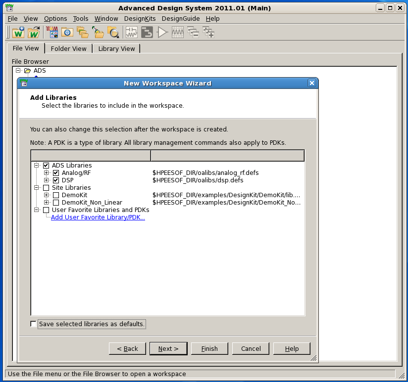
3 Fig. 3 3

4 Fig. 4 4

5 Fig. 5 5
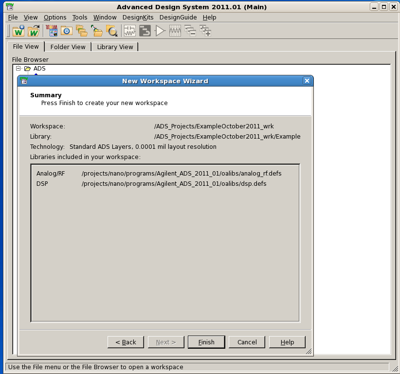
6 Fig. 6 6


7 Fig. 7 After you click on the 'finish' icon, then you will end up with Fig. 7. Now you can create symbol, schematics, layout,... In order to make a new schematic, choose File> New > Schematic. Then a new window appears and you should provide a name for your schematic. Fig. 8 7

8 Fig. 9 After opening a New Schematic window, a dialog window appears that provides help with circuit or simulation settings, you can also choose ''Don't show this dialog again''. Creating Schematic: Before starting you can set the units from Options>Preferences>Units/Scale. Components can be selected either form Component Palette or Component library. Palette list: The Palette list is on the left side of the schematic window. In the Palette list you see all the libraries with their components. Select one component and move the cursor in the drawing area, you will see a ghost image. Place it wherever you like and press Esc to end it. Component library: For selecting components from Component library choose Insert>Component>Component Library, then a dialog box appears which list the libraries with their components. After selecting a component, 8

9 drag it into the schematic window then a ghost image moves along the cursor. Place the component wherever you want, press Esc to end the command. Fig. 10 For rotating a component use Ctrl+r or use Edit>Rotate For copying a component use Ctrl+c or use Edit>copy For pasting a component use Ctrl+p or use Edit>paste For editing a component double click on it, then a window appears with all the parameters of the component. For connecting the components click on Insert Wire icon. For labeling the wires click on Name icon. After choosing a desired name click on the desired wire to label it. Fig. 10 9
10 Simulation/Example_1: Draw the circuit which is shown in the following figure: -From Palett choose: Lumped_Componenet library, then select R. Fig. 11 Sources_Time Domain library, then select Sine source Tlines_Microstrip, then select MLIN and MSUB components. MSUB defines the properties of the microstrip lines, for this simulation we use RO4350B. RO4000 Series High Frequency Circuit Materials are glass reinforced hydrocarbon/ceramic laminates (Not PTFE) designed for performance sensitive, high volume commercial applications. Double click on MSUB and set the following parameters: H 1.52 mm Substrate thickness Er 3.48 Relative dielectric constant Cond 5.8 e+07 S/m Conductor conductivity. (Copper) T 0.06 mm Conductor thickness TanD Dielectric loss tangent Simulation_DC, select DC Simulation_Transient, select Trans -Edit the components according to given parameters in pervious figure. -For calculating the 'W' and 'L' of the MLIN, use transmission line calculator (LineCalc). Choose Tools>LineCalc>StartLineCalc then a dialog box appears. Fill out the Substrate parameters as given above. Set Z0 is the characteristic impedance of the transmission line. E_Eff is Effective electrical length of line in degree *lamda is 30 degrees and 0.166*lamda is 60 degrees. Set Freq to 5 GHz After setting all the parameters press 'Synthesize' to calculate the 'W' and 'L' 10

11 Fig. 12 -Save the design and click on gear icon to simulate the circuit. 11

12 Fig. 13 After simulation finishes, the Data Display window opens. From palette in Data Display window you can choose different charts to display simulation results. -From Palette choose the Rectangular Plot. A Plot Traces & Attributes window pops up, from plot type tab select the desired parameters to be plotted and Add them, then press OK. Fig. 14 Here is a plot of simulated results. As can be seen the phase difference between voltage of node1 and voltage of node4 is =90 degrees. 12

13 Fig. 15 In the schematic window, if you choose Simulate>Annotate DC Solution then DC current of all branches and DC voltage of all nodes are displayed on the circuit, if choose Simulate>Clear DC Annotation they will be erased. Here you can find Advanced Design System 2009 Documentation: 13
Creating a new project: Choose File> New Project. A dialog box appears and asking about the work directory that by default
 Advanced Design System (ADS) Tutorial: ADS is a simulator like spice, cadence. But it focuses on the RF and microwave design, so most of its devices on the library are microwave devices. Circuit Simulation:
Lab 1: Introduction to PSpice
 Lab 1: Introduction to PSpice Objectives A primary purpose of this lab is for you to become familiar with the use of PSpice and to learn to use it to assist you in the analysis of circuits. The software
ELC 4383 RF/Microwave Circuits I Laboratory 3: Optimization Using Advanced Design System Software
 1 EL 4383 RF/Microwave ircuits I Laboratory 3: Optimization Using Advanced Design System Software Note: This lab procedure has been adapted from a procedure written by Dr. Tom Weller at the University
3. On the top menu bar, click on File > New > Project as shown in Fig. 2 below: Figure 2 Window for Orcad Capture CIS
 Department of Electrical Engineering University of North Texas Denton, TX. 76207 EENG 2920 Quickstart PSpice Tutorial Tutorial Prepared by Oluwayomi Adamo 1. To run the PSpice program, click on Start >
Copyright 2011 Linear Technology. All rights reserved.
 Copyright. All rights reserved. LTspice IV Getting Started Guide 2 Benefits of Using LTspice IV Stable SPICE circuit simulation with Unlimited number of nodes Schematic/symbol editor Waveform viewer Library
The Critical Length of a Transmission Line
 Page 1 of 9 The Critical Length of a Transmission Line Dr. Eric Bogatin President, Bogatin Enterprises Oct 1, 2004 Abstract A transmission line is always a transmission line. However, if it is physically
Introduction to Simulink
 Introduction to Simulink MEEN 364 Simulink is a software package for modeling, simulating, and analyzing dynamical systems. It supports linear and nonlinear systems, modeled in continuous time, sampled
EE 242 EXPERIMENT 5: COMPUTER SIMULATION OF THREE-PHASE CIRCUITS USING PSPICE SCHEMATICS 1
 EE 242 EXPERIMENT 5: COMPUTER SIMULATION OF THREE-PHASE CIRCUITS USING PSPICE SCHEMATICS 1 Objective: To build, simulate, and analyze three-phase circuits using OrCAD Capture Pspice Schematics under balanced
How To Use Multiisim On A Computer Or A Circuit Design Suite 10.0 (Aero)
") MULTISIM TUTORIAL Start Click on Start All Programs National Instruments Circuit Design Suite 10.0 Multisim. Component Toolbar Ammeter/ Voltmeter Toolbar Virtual Component Toolbar Simulation Toolbar Instrument
MULTISIM TUTORIAL Start Click on Start All Programs National Instruments Circuit Design Suite 10.0 Multisim. Component Toolbar Ammeter/ Voltmeter Toolbar Virtual Component Toolbar Simulation Toolbar Instrument
University of California, Berkeley Department of Electrical Engineering and Computer Sciences EE 105: Microelectronic Devices and Circuits
 University of California, Berkeley Department of Electrical Engineering and Computer Sciences EE 105: Microelectronic Devices and Circuits LTSpice LTSpice is a free circuit simulator based on Berkeley
Document Contents Introduction Layout Extraction with Parasitic Capacitances Timing Analysis DC Analysis
 Cadence Tutorial C: Simulating DC and Timing Characteristics Created for the MSU VLSI program by Professor A. Mason and the AMSaC lab group rev S06 (convert to spectre simulator) Document Contents Introduction
Application Note: PCB Design By: Wei-Lung Ho
 Application Note: PCB Design By: Wei-Lung Ho Introduction: A printed circuit board (PCB) electrically connects circuit components by routing conductive traces to conductive pads designed for specific components
ADS Tutorial Stability and Gain Circles ECE145A/218A
 ADS Tutorial Stability and Gain Circles ECE145A/218A The examples in this tutorial can be downloaded from xanadu.ece.ucsb.edu/~long/ece145a as the file: stab_gain.zap The first step in designing the amplifier
Designing a Schematic and Layout in PCB Artist
 Designing a Schematic and Layout in PCB Artist Application Note Max Cooper March 28 th, 2014 ECE 480 Abstract PCB Artist is a free software package that allows users to design and layout a printed circuit
Qucs. A Tutorial. Getting Started with Qucs. Stefan Jahn Juan Carlos Borrás
 Qucs A Tutorial Getting Started with Qucs Stefan Jahn Juan Carlos Borrás Copyright c 2007 Stefan Jahn Copyright c 2007 Juan Carlos Borrás Permission is granted to
Project 1: Rectangular Waveguide (HFSS)
") Project 1: Rectangular Waveguide (HFSS) b ε r a a = 0.9 (2.286cm) b = 0.4 (1.016cm) ε r = 1.0 Objective Getting Started with HFSS (a tutorial) Using HFSS, simulate an air-filled WR-90 waveguide shown above.
Project 1: Rectangular Waveguide (HFSS) b ε r a a = 0.9 (2.286cm) b = 0.4 (1.016cm) ε r = 1.0 Objective Getting Started with HFSS (a tutorial) Using HFSS, simulate an air-filled WR-90 waveguide shown above.
Mentor Tools tutorial Bold Browser Design Manager Design Architect Library Components Quicksim Creating and Compiling the VHDL Model.
 Mentor Tools tutorial Bold Browser Design Manager Design Architect Library Components Quicksim Creating and Compiling the VHDL Model. Introduction To Mentor Graphics Mentor Graphics BOLD browser allows
Capacitor Self-Resonance
 Capacitor Self-Resonance By: Dr. Mike Blewett University of Surrey United Kingdom Objective This Experiment will demonstrate some of the limitations of capacitors when used in Radio Frequency circuits.
MATERIALS. Multisim screen shots sent to TA.
 Page 1/8 Revision 0 9-Jun-10 OBJECTIVES Learn new Multisim components and instruments. Conduct a Multisim transient analysis. Gain proficiency in the function generator and oscilloscope. MATERIALS Multisim
100 ADS Design Examples A Design Approach Using (ADS)
") 100 ADS Design Examples A Design Approach Using (ADS) Chapter 2: Transmission Line Components Ali Behagi 2 100 ADS Design Examples 100 ADS Design Examples A Design Approach Using (ADS) Chapter 2: Transmission
100 ADS Design Examples A Design Approach Using (ADS) Chapter 2: Transmission Line Components Ali Behagi 2 100 ADS Design Examples 100 ADS Design Examples A Design Approach Using (ADS) Chapter 2: Transmission
Using ADS to simulate Noise Figure
 Using ADS to simulate Noise Figure ADS can be used to design low noise amplifiers much in the same way you have already used it for MAG or MSG designs. Noise circles and available gain circles are the
Jump-Start Tutorial For ProcessModel
 Jump-Start Tutorial For ProcessModel www.blueorange.org.uk ProcessModel Jump-Start Tutorial This tutorial provides step-by-step instructions for creating a process model, running the simulation, and viewing
Circuit Simulation and Technical Support Tools
 TDK EMC Technology Practice Section Circuit Simulation and Technical Support Tools TDK Corporation Application Center Tetsuya Umemura, Katsushi Ebata 1 Utilization of Computer Simulation In recent years,
Utilizing Time Domain (TDR) Test Methods For Maximizing Microwave Board Performance
 Test Methods For Maximizing Microwave Board Performance") The Performance Leader in Microwave Connectors Utilizing Time Domain (TDR) Test Methods For Maximizing Microwave Board Performance.050 *.040 c S11 Re REF 0.0 Units 10.0 m units/.030.020.010 1.0 -.010 -.020
The Performance Leader in Microwave Connectors Utilizing Time Domain (TDR) Test Methods For Maximizing Microwave Board Performance.050 *.040 c S11 Re REF 0.0 Units 10.0 m units/.030.020.010 1.0 -.010 -.020
Introduction to LTspice IV Workshop
 Introduction to LTspice IV Workshop Presented by: Steve Knudtsen FAE Linear Technology [email protected] Copyright 2009 Linear Technology. All rights reserved. Why Use LTspice? Stable SPICE circuit
PSPICE TUTORIAL (BASIC)
") Department of Electrical & Computer Engineering PSPICE TUTORIAL (BASIC) Professor: Dr. Subbarao V. Wunnava Teaching Assistant: Rafael Romero COURTESY: ED LULE/ BORIS LINO/ORCAD Updated: Spring.2006, 07
Department of Electrical & Computer Engineering PSPICE TUTORIAL (BASIC) Professor: Dr. Subbarao V. Wunnava Teaching Assistant: Rafael Romero COURTESY: ED LULE/ BORIS LINO/ORCAD Updated: Spring.2006, 07
S-parameter Simulation and Optimization
 S-parameter Simulation and Optimization Slide 5-1 S-parameters are Ratios Usually given in db as 20 log of the voltage ratios of the waves at the ports: incident, reflected, or transmitted. S-parameter
Copyrights. Software, documentation and related materials: Copyright 2002 Altium Limited
 Signal Integrity Copyrights Software, documentation and related materials: Copyright 2002 Altium Limited This software product is copyrighted and all rights are reserved. The distribution and sale of this
SIMULATIONS OF PARALLEL RESONANT CIRCUIT POWER ELECTRONICS COLORADO STATE UNIVERSITY
 SIMULATIONS OF PARALLEL RESONANT CIRCUIT POWER ELECTRONICS COLORADO STATE UNIVERSITY Page 1 of 25 PURPOSE: The purpose of this lab is to simulate the LCC circuit using MATLAB and ORCAD Capture CIS to better
UNIVERSITY OF CALIFORNIA College of Engineering Department of Electrical Engineering and Computer Sciences
 UNIVERSITY OF CALIFORNIA College of Engineering Department of Electrical Engineering and Computer Sciences Jan M. Rabaey Homework #1: Circuit Simulation EECS 141 Due Friday, January 30, 5pm, box in 240
CONCEPT-II. Overview of demo examples
 CONCEPT-II CONCEPT-II is a frequency domain method of moment (MoM) code, under development at the Institute of Electromagnetic Theory at the Technische Universität Hamburg-Harburg (www.tet.tuhh.de). Overview
RLC Series Resonance
 RLC Series Resonance 11EM Object: The purpose of this laboratory activity is to study resonance in a resistor-inductor-capacitor (RLC) circuit by examining the current through the circuit as a function
RF Network Analyzer Basics
 RF Network Analyzer Basics A tutorial, information and overview about the basics of the RF Network Analyzer. What is a Network Analyzer and how to use them, to include the Scalar Network Analyzer (SNA),
Lab 1: Full Adder 0.0
 Lab 1: Full Adder 0.0 Introduction In this lab you will design a simple digital circuit called a full adder. You will then use logic gates to draw a schematic for the circuit. Finally, you will verify
Xilinx ISE. <Release Version: 10.1i> Tutorial. Department of Electrical and Computer Engineering State University of New York New Paltz
 Xilinx ISE Tutorial Department of Electrical and Computer Engineering State University of New York New Paltz Fall 2010 Baback Izadi Starting the ISE Software Start ISE from the
Laboratory 2. Exercise 2. Exercise 2. PCB Design
 Exercise 2. PCB Design Aim of the measurement Introducing to the PCB design Creating a schematic of an analog circuit, making simulations on it and designing a Printed circuit board for it. Keywords Printed
Microwave Amplifier Design (part 1)
") San Jose State University Department of Electrical Engineering ELECTRICAL ENGINEERING SENIOR PROJECT Microwave Amplifier Design (part 1) by Steve Garcia Jaime Cordoba Inderpreet Obhi December 15, 2003
San Jose State University Department of Electrical Engineering ELECTRICAL ENGINEERING SENIOR PROJECT Microwave Amplifier Design (part 1) by Steve Garcia Jaime Cordoba Inderpreet Obhi December 15, 2003
TINA-TI. Analog circuit simulation made easy! Thomas Kuehl Senior Applications Engineer HPA Linear Products
 TINA-TI Analog circuit simulation made easy! Thomas Kuehl Senior Applications Engineer HPA Linear Products Welcome to the Texas Instruments TINA-TI session. TINA-TI is easy to use circuit simulation software
Agilent EEsof EDA. www.agilent.com/find/eesof
 Agilent EEsof EDA This document is owned by Agilent Technologies, but is no longer kept current and may contain obsolete or inaccurate references. We regret any inconenience this may cause. For the latest
Simulation and Design Route Development for ADEPT-SiP
 Simulation and Design Route Development for ADEPT-SiP Alaa Abunjaileh, Peng Wong and Ian Hunter The Institute of Microwaves and Photonics School of Electronic and Electrical Engineering The University
Electronic WorkBench tutorial
 Electronic WorkBench tutorial Introduction Electronic WorkBench (EWB) is a simulation package for electronic circuits. It allows you to design and analyze circuits without using breadboards, real components
Beginner s Guide to LTSpice
 Beginner s Guide to LTSpice Pages 1&2 Pages 3 4 Page 4 Pages 5 9 Pages 10 11 Page 11 Commands & techniques for drawing the circuit Commands and methods for analysis of the circuit Additional notes (crystals
Agilent EEsof EDA. www.agilent.com/find/eesof
 Agilent EEsof EDA This document is owned by Agilent Technologies, but is no longer kept current and may contain obsolete or inaccurate references. We regret any inconenience this may cause. For the latest
Impedance Matching and Matching Networks. Valentin Todorow, December, 2009
 Impedance Matching and Matching Networks Valentin Todorow, December, 2009 RF for Plasma Processing - Definition of RF What is RF? The IEEE Standard Dictionary of Electrical and Electronics Terms defines
PCB Artist Tutorial:
 Derek Brower [email protected] Capstone Design Team 6 PCB Artist Tutorial: Printed Circuit Board Design Basics N o v e m b e r 1 4, 2 0 1 2 P C B B a s i c s P a g e 1 Abstract PCB Artist is a schematic
Lab 3: Introduction to Data Acquisition Cards
 Lab 3: Introduction to Data Acquisition Cards INTRODUCTION: In this lab, you will be building a VI to display the input measured on a channel. However, within your own VI you will use LabVIEW supplied
Comprehensive Analysis of Flexible Circuit Materials Performance in Frequency and Time Domains
 Comprehensive Analysis of Flexible Circuit Materials Performance in Frequency and Time Domains Glenn Oliver and Deepu Nair DuPont Jim Nadolny Samtec, Inc. [email protected] [email protected]
OrCAD Flow Tutorial. Product Version 10.0 Februaruy 2004
 OrCAD Flow Tutorial Product Version 10.0 Februaruy 2004 2003-2004 Cadence Design Systems, Inc. All rights reserved. Printed in the United States of America. Cadence Design Systems, Inc., 555 River Oaks
PCB Design with Altium: Schematic Entry, Libraries, and Designing Components
 PCB Design with Altium: Schematic Entry, Libraries, and Designing Components Alex Fosdick Capstone Senior Design Instructor: Tom Brown Edited: Jan 30th 2011 Description: This document is the first of two
Creating Subcircuits and Hierarchical Blocks in LTspice Mike Kelsch January 2007
 Mike Kelsch January 2007 This tutorial gives some techniques for creating Subcircuits and Hierarchical Blocks using LTspice /SwitcherCAD III Version 2.19p (available free from Linear Technology at: http://www.linear.com/company/software.jsp).
WebEx Sharing Resources
 WebEx Sharing Resources OTS PUBLICATION: WX0 REVISED: 4/8/06 04 TOWSON UNIVERSITY OFFICE OF TECHNOLOGY SERVICES =Shortcut =Advice =Caution Introduction During a WebEx session, the host has the ability
Lab 7: Operational Amplifiers Part I
 Lab 7: Operational Amplifiers Part I Objectives The objective of this lab is to study operational amplifier (op amp) and its applications. We will be simulating and building some basic op amp circuits,
Complete. PCB Design Using. NI Multisim, NI Ultiboard, LPKF CircuitCAM and BoardMaster. pg. 1. Wei Siang Pee
 Complete Wei Siang Pee PCB Design Using NI Multisim, NI Ultiboard, LPKF CircuitCAM and BoardMaster pg. 1 Introduction Multisim equips educators, students, and professionals with the tools to analyze circuit
Executive Summary. Table of Contents
 Executive Summary How to Create a Printed Circuit Board (PCB) Department of Electrical & Computer Engineering Michigan State University Prepared by: John Kelley Revision: 4/06/00 This application note
Application Note. PCIEC-85 PCI Express Jumper. High Speed Designs in PCI Express Applications Generation 3-8.0 GT/s
 PCIEC-85 PCI Express Jumper High Speed Designs in PCI Express Applications Generation 3-8.0 GT/s Copyrights and Trademarks Copyright 2015, Inc. COPYRIGHTS, TRADEMARKS, and PATENTS Final Inch is a trademark
Lab #9: AC Steady State Analysis
 Theory & Introduction Lab #9: AC Steady State Analysis Goals for Lab #9 The main goal for lab 9 is to make the students familar with AC steady state analysis, db scale and the NI ELVIS frequency analyzer.
Tutorial 2: Using Excel in Data Analysis
 Tutorial 2: Using Excel in Data Analysis This tutorial guide addresses several issues particularly relevant in the context of the level 1 Physics lab sessions at Durham: organising your work sheet neatly,
Series and Parallel Resistive Circuits
 Series and Parallel Resistive Circuits The configuration of circuit elements clearly affects the behaviour of a circuit. Resistors connected in series or in parallel are very common in a circuit and act
Introduction to OrCAD Capture and PSpice
 Introduction to OrCAD Capture and PSpice Professor John H. Davies September 18, 2008 Abstract This handout explains how to get started with Cadence OrCAD to draw a circuit (schematic capture) and simulate
Introduction to Visio 2003 By Kristin Davis Information Technology Lab School of Information The University of Texas at Austin Summer 2005
 Introduction to Visio 2003 By Kristin Davis Information Technology Lab School of Information The University of Texas at Austin Summer 2005 Introduction This tutorial is designed for people who are new
OrCAD Capture with PSpice and Allegro DE CIS with AMS Simulator. Describes how to create a PSpice Archive File with Capture
 Title: Product: Summary: Creating a Project Archive OrCAD Capture with PSpice and Allegro DE CIS with AMS Simulator Describes how to create a PSpice Archive File with Capture Author/Date: Wei Ling / 03.08.2009
APN1001: Circuit Models for Plastic Packaged Microwave Diodes
 APPLICATION NOTE APN11: Circuit Models for Plastic Packaged Microwave Diodes Abstract This paper reports on the measurement and establishment of circuit models for SOT-23 and SOD-323 packaged diodes. Results
EXPRESS PCB TUTORIAL Author: Lee Morey Revised: JE Feb 2015
 EXPRESS PCB TUTORIAL Author: Lee Morey Revised: JE Feb 2015 Getting Started There are several resources for learning how to layout schematics and PCBs. And there are several popular commercial packages.
Physics 3330 Experiment #2 Fall 1999. DC techniques, dividers, and bridges R 2 =(1-S)R P R 1 =SR P. R P =10kΩ 10-turn pot.
R P R 1 =SR P. R P =10kΩ 10-turn pot.") Physics 3330 Experiment #2 Fall 1999 DC techniques, dividers, and bridges Purpose You will gain a familiarity with the circuit board and work with a variety of DC techniques, including voltage dividers,
Physics 3330 Experiment #2 Fall 1999 DC techniques, dividers, and bridges Purpose You will gain a familiarity with the circuit board and work with a variety of DC techniques, including voltage dividers,
Lecture 24. Inductance and Switching Power Supplies (how your solar charger voltage converter works)
") Lecture 24 Inductance and Switching Power Supplies (how your solar charger voltage converter works) Copyright 2014 by Mark Horowitz 1 Roadmap: How Does This Work? 2 Processor Board 3 More Detailed Roadmap
Lecture 24 Inductance and Switching Power Supplies (how your solar charger voltage converter works) Copyright 2014 by Mark Horowitz 1 Roadmap: How Does This Work? 2 Processor Board 3 More Detailed Roadmap
Connectivity in a Wireless World. Cables Connectors 2014. A Special Supplement to
 Connectivity in a Wireless World Cables Connectors 204 A Special Supplement to Signal Launch Methods for RF/Microwave PCBs John Coonrod Rogers Corp., Chandler, AZ COAX CABLE MICROSTRIP TRANSMISSION LINE
Laboratory 4: Feedback and Compensation
 Laboratory 4: Feedback and Compensation To be performed during Week 9 (Oct. 20-24) and Week 10 (Oct. 27-31) Due Week 11 (Nov. 3-7) 1 Pre-Lab This Pre-Lab should be completed before attending your regular
Introduction to the TI-Nspire CX
 Introduction to the TI-Nspire CX Activity Overview: In this activity, you will become familiar with the layout of the TI-Nspire CX. Step 1: Locate the Touchpad. The Touchpad is used to navigate the cursor
Jianjian Song LogicWorks 4 Tutorials (5/15/03) Page 1 of 14
 Page 1 of 14") LogicWorks 4 Tutorials Jianjian Song Department of Electrical and Computer Engineering Rose-Hulman Institute of Technology March 23 Table of Contents LogicWorks 4 Installation and update...2 2 Tutorial
LogicWorks 4 Tutorials Jianjian Song Department of Electrical and Computer Engineering Rose-Hulman Institute of Technology March 23 Table of Contents LogicWorks 4 Installation and update...2 2 Tutorial
In this example, Mrs. Smith is looking to create graphs that represent the ethnic diversity of the 24 students in her 4 th grade class.
 Creating a Pie Graph Step-by-step directions In this example, Mrs. Smith is looking to create graphs that represent the ethnic diversity of the 24 students in her 4 th grade class. 1. Enter Data A. Open
Sample Table. Columns. Column 1 Column 2 Column 3 Row 1 Cell 1 Cell 2 Cell 3 Row 2 Cell 4 Cell 5 Cell 6 Row 3 Cell 7 Cell 8 Cell 9.
 Working with Tables in Microsoft Word The purpose of this document is to lead you through the steps of creating, editing and deleting tables and parts of tables. This document follows a tutorial format
Animating in Inventor Studio the basics
 Animating in Inventor Studio the basics This tutorial is provided at no cost to Autodesk Inventor users by B2 Design. Anyone downloading or viewing the tutorial does not have permission to copy any part
VIETNAM NATIONAL UNIVERSITY HOCHIMINH CITY INTERNATIONAL UNIVERSITY SCHOOL OF ELECTRICAL ENGINEERING
 VIETNAM NATIONAL UNIVERSITY HOCHIMINH CITY INTERNATIONAL UNIVERSITY SCHOOL OF ELECTRICAL ENGINEERING BUILD A METHOD TO MEASURE THE RELATIVE PERMITTIVITY OF THE SUBSTRATE OF A PCB USING VECTOR NETWORK ANALYZER
Planar Inter Digital Capacitors on Printed Circuit Board
 1 Planar Inter Digital Capacitors on Printed Circuit Board Ajayan K.R., K.J.Vinoy Department of Electrical Communication Engineering Indian Institute of Science, Bangalore, India 561 Email {ajayanr jvinoy}
KiCad Step by Step Tutorial
 KiCad Step by Step Tutorial Copyright 2006 David Jahshan: kicad at iridec.com.au 2011 Update Copyright 2011 Phil Hutchinson Copyright: Please freely copy and distribute (sell or give away) this document
Eatman Associates 2014 Rockwall TX 800-388-4036 rev. October 1, 2014. Striplines and Microstrips (PCB Transmission Lines)
") Eatman Associates 2014 Rockwall TX 800-388-4036 rev. October 1, 2014 Striplines and Microstrips (PCB Transmission Lines) Disclaimer: This presentation is merely a compilation of information from public
Eatman Associates 2014 Rockwall TX 800-388-4036 rev. October 1, 2014 Striplines and Microstrips (PCB Transmission Lines) Disclaimer: This presentation is merely a compilation of information from public
Tutorials Drawing a 555 timer circuit
 Step 1 of 10: Introduction This tutorial shows you how to make an electronic circuit using Livewire and PCB Wizard 3. You should follow this tutorial to learn the basic skills you will need to use Livewire
Data Logging Software and Cable Bundle Model DL-SC3 User Manual. Overview
 Data Logging Software and Cable Bundle Model DL-SC3 User Manual Overview Eco Sensors Digital Products are capable of transmitting data to a computer via an RS-232 serial connection. Eco Sensors DL-SC3
Curriculum and Concept Module Development in RF Engineering
 Introduction Curriculum and Concept Module Development in RF Engineering The increasing number of applications students see that require wireless and other tetherless network solutions has resulted in
OrCAD Lite Products Reference
 Product Version 16.6 October 2012 Updated on: February 19, 2014 1991 2014 Cadence Design Systems, Inc. All rights reserved. Portions Apache Software Foundation, Sun Microsystems, Free Software Foundation,
Electronic filters design tutorial -2
 In the first part of this tutorial we explored the bandpass filters designed with lumped elements, namely inductors and capacitors. In this second part we will design filters with distributed components
Introduction to SPSS 16.0
 Introduction to SPSS 16.0 Edited by Emily Blumenthal Center for Social Science Computation and Research 110 Savery Hall University of Washington Seattle, WA 98195 USA (206) 543-8110 November 2010 http://julius.csscr.washington.edu/pdf/spss.pdf
Product Description. Ordering Information. GaAs HBT GaAs MESFET InGaP HBT
 Basestation Applications Cellular and PCS Systems CDMA, W-CDMA Systems GSM/EDGE Systems Final PA for Low-Power Applications RF3223Low Noise, Linear Amplifier High Linearity/Driver Amplifier RF3223 LOW
Summary of important mathematical operations and formulas (from first tutorial):
:") EXCEL Intermediate Tutorial Summary of important mathematical operations and formulas (from first tutorial): Operation Key Addition + Subtraction - Multiplication * Division / Exponential ^ To enter a
EXCEL Intermediate Tutorial Summary of important mathematical operations and formulas (from first tutorial): Operation Key Addition + Subtraction - Multiplication * Division / Exponential ^ To enter a
2. A conductor of length 2m moves at 4m/s at 30 to a uniform magnetic field of 0.1T. Which one of the following gives the e.m.f. generated?
 Extra Questions - 2 1. A straight length of wire moves through a uniform magnetic field. The e.m.f. produced across the ends of the wire will be maximum if it moves: a) along the lines of magnetic flux
Merlin PCB Designer Printed circuit design using CorelDRAW
 Merlin PCB Designer Printed circuit design using CorelDRAW Shareware version 2.1 - for CorelDRAW 7 to 11 Introduction Probably you are professionally involved with printed circuit board manufacturing,
Information Technology Solutions
 Connecting People, Process Information & Data Network Systems Diagnostic Testing Information Technology Solutions Getting started in Workflow Designer Prior Learning 1. While it helps to have some knowledge
Impedance Matching Utility
 Impedance Matching Utility September 2006 Notice The information contained in this document is subject to change without notice. Agilent Technologies makes no warranty of any kind with regard to this material,
A Guide to Using Excel in Physics Lab
 A Guide to Using Excel in Physics Lab Excel has the potential to be a very useful program that will save you lots of time. Excel is especially useful for making repetitious calculations on large data sets.
Keysight Technologies Understanding the Fundamental Principles of Vector Network Analysis. Application Note
 Keysight Technologies Understanding the Fundamental Principles of Vector Network Analysis Application Note Introduction Network analysis is the process by which designers and manufacturers measure the
Creating a Gradebook in Excel
 Creating a Spreadsheet Gradebook 1 Creating a Gradebook in Excel Spreadsheets are a great tool for creating gradebooks. With a little bit of work, you can create a customized gradebook that will provide
Click on various options: Publications by Wizard Publications by Design Blank Publication
 Click on various options: Publications by Wizard Publications by Design Blank Publication Select the Blank Publications Tab: Choose a blank full page Click on Create New Page Insert > Page Select the number
2. The Vector Network Analyzer
 ECE 584 Laboratory Experiments 2. The Vector Network Analyzer Introduction: In this experiment we will learn to use a Vector Network Analyzer to measure the magnitude and phase of reflection and transmission
Heterojunction Bipolar Transistor Technology (InGaP HBT) Broadband High Linearity Amplifier
 Broadband High Linearity Amplifier") Freescale Semiconductor Technical Data Heterojunction Bipolar Transistor Technology (InGaP HBT) Broadband High Linearity Amplifier The is a general purpose amplifier that is input and output internally
Freescale Semiconductor Technical Data Heterojunction Bipolar Transistor Technology (InGaP HBT) Broadband High Linearity Amplifier The is a general purpose amplifier that is input and output internally
2.996/6.971 Biomedical Devices Design Laboratory Lecture 2: Fundamentals and PCB Layout
 2.996/6.971 Biomedical Devices Design Laboratory Lecture 2: Fundamentals and PCB Layout Instructor: Hong Ma Sept. 12, 2007 Fundamental Elements Resistor (R) Capacitor (C) Inductor (L) Voltage Source Current
Efficient Meshing in Sonnet
 100 Elwood Davis Road North Syracuse, NY 13212 USA Efficient Meshing in Sonnet Volker Mühlhaus Dr. Mühlhaus Consulting & Software GmbH 2008 Sonnet Software, Inc. Sonnet is a registered trademark of Sonnet
Extending Rigid-Flex Printed Circuits to RF Frequencies
 Extending -Flex Printed Circuits to RF Frequencies Robert Larmouth Teledyne Electronic Technologies 110 Lowell Rd., Hudson, NH 03051 (603) 889-6191 Gerald Schaffner Schaffner Consulting 10325 Caminito
Application Note SAW-Components
 Application Note SAW-Components Principles of SAWR-stabilized oscillators and transmitters. App: Note #1 This application note describes the physical principle of SAW-stabilized oscillator. Oscillator
Module 22: Signal Integrity
 Module 22: Signal Integrity Module 22: Signal Integrity 22.1 Signal Integrity... 22-1 22.2 Checking Signal Integrity on an FPGA design... 22-3 22.2.1 Setting Up...22-3 22.2.2 Importing IBIS Models...22-3
FREQUENCY RESPONSE OF AN AUDIO AMPLIFIER
 2014 Amplifier - 1 FREQUENCY RESPONSE OF AN AUDIO AMPLIFIER The objectives of this experiment are: To understand the concept of HI-FI audio equipment To generate a frequency response curve for an audio