Structural Forensic Engineering Case Study : MRR2 Project. Prof. Dr. Azlan Abdul Rahman Forensic Engineering Universiti Teknologi Malaysia
|
|
|
- Shawn Snow
- 9 years ago
- Views:
Transcription
1 Structural Forensic Engineering Case Study : MRR2 Project Prof. Dr. Azlan Abdul Rahman Forensic Engineering Universiti Teknologi Malaysia All information and data presented in these slides are strictly for academic use in the subject MAE1033 only and should not be used or cited for any other purpose without prior approval of the author. UTM 2011

2 Background The STAR Newspaper, Tuesday, August 10, 2004

3 The Observed Cracks

4 In The News The Star Online > Thursday August 26, 2004 ACA to probe technical aspects of MRR2 flyover SHAH ALAM: The Anti-Corruption Agency (ACA), apart from investigating possible fraud in the construction of the 1.7km flyover along the Middle Ring Road 2 (MRR2), will check whether it was built according to specifications. The ACA, which obtained documents relating to the building of Package 11 of the MRR2, which cost RM238.8mil, from the Public Works Department two weeks ago, is now focusing on the technical aspects of the flyover to check for any discrepancies in its construction. An eight-man team from the ACA s Engineering Forensic Unit took samples from the damaged pillars and beams and sent them for composition and durability analysis on Tuesday. An ACA source said the analysis would show whether the concrete chunks were mixed and laid out according to the road construction industry's specifications. The investigations will focus on whether those involved cut corners to reap higher profits at the expense of safety and durability. The technical team will verify whether the builder had adhered to the specifications outlined in its building plan, he said. The investigation team led by Rosli Ali measured the length, width and depth of the flyover's pillars and beams. Works Minister Datuk Seri S. Samy Vellu had on Aug 9 ordered the flyover to be closed to traffic after experts found it to be a threat to public safety. He said it would cost RM20mil to repair the flyover located between Taman Bukit Maluri and the Forest Research Institute of Malaysia.

5 Cracks due to Design Works Minister on MRR2 Flyover Yesterday (March, 17, 2006), Works Minister Samy Vellu admitted in Parliament that defective design was one of the reasons for the cracks in the Middle Ring Road 2 (MRR2). "The steel placement did not follow specifications," Samy said in reply to a question from Speaker Tan Sri Ramli Ngah Talib. Ramli had interrupted Samy Vellu when the minister was giving a technical explanation for the cracks on the MRR2 highway in reply to questions from Datuk Ismail Sabri Yaakob (BN-Bera) and other MPs. Samy Vellu said his ministry monitored bridges and flyovers but only the MRR2 was found to have "serious defects".

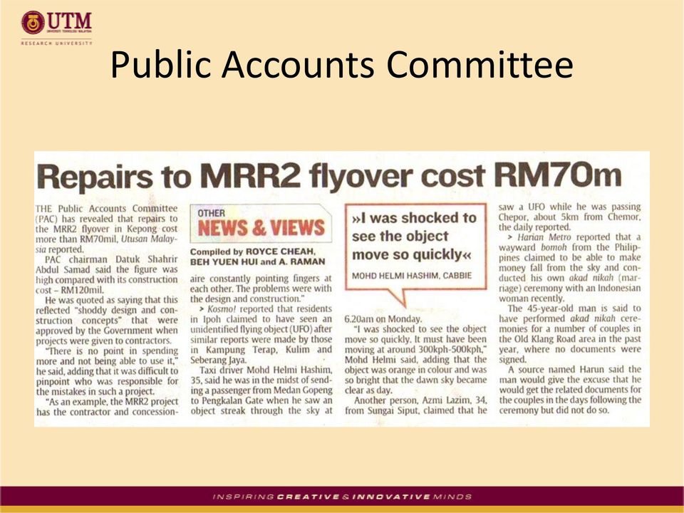
6 Public Accounts Committee
7 Pier Crosshead

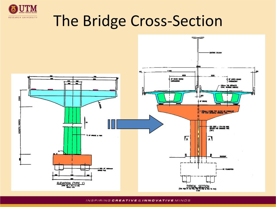
8 The Bridge Cross-Section
9 Aim of Forensic Investigation Forensics engineering : a failure analysis program for litigation support The goal is to positively identify the sequence of events leading to failure Common causes of failure may be found in deficiencies in design, detailing, material, or workmanship.

10 Objectives Verification of crack mapping and observation of new cracks or defects Verification of concrete strength measurement Design check on pier crosshead Finite element analysis of pier crosshead Document study on construction methods and contractual matters

11 In-Situ Testing Visual inspection & observation of defects Overview of Methodology Crack Mapping In-situ strength Measurement Check size, nos. & location of Steel bars Observation of Core samples (voids, cracks) Cracks and other defects Low quality concrete Low concrete strength Not following design specifications Not following material specifications Not following construction method or procedures ACA Clause 11(c) Falsification of Documents Laboratory Testing Chemical tests Core testing For strength Design Check Document Study

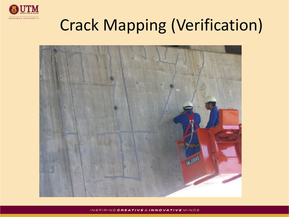
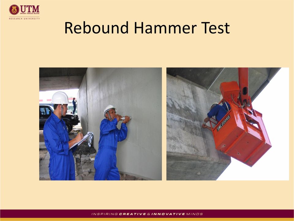
12 In-Situ Testing Visual inspection and selective crack mapping for verification of previous test records and identification of new cracks or defects In-situ hardness test using rebound hammer on selected locations to provide estimate of concrete quality and strength correlation Core-drilling to extract concrete core samples from selected locations for strength and other relevant tests

13 Crack Mapping (Verification)
14 Rebound Hammer Test
15 Hardness Test Results Member Average Rebound Number Estimated Evaluation of the Concrete Quality Pier 33 crosshead 55 Sound concrete Pier 32 crosshead 53 Sound concrete Pier 30 crosshead 53 Sound concrete Pier 3 crosshead 56 Sound concrete Pier 2 crosshead 55 Sound concrete Pier 32 column 57 Sound concrete Pier 31 column 56 Sound concrete Pier 30 column 58 Sound concrete Abutment A 54 Sound concrete Abutment B 54 Sound concrete

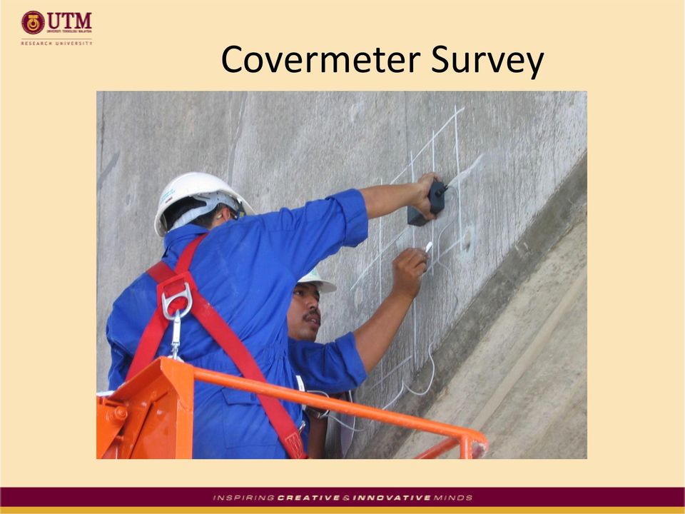
16 Covermeter Survey
17 Core Drilling Core-drilling was carried out at 10 selected locations in the abutments and crossheads of selected piers to extract concrete core samples for checking and verifying the material strength. The drilling was carried out by skilled operators using a portable rotary cutting equipment and uniformity of pressure during drilling was achieved. All holes made by coring were filled up by special non-shrink grout to ensure that they were completely filled up and having smooth surface.

18 In-Situ Core Drilling

19 Brief Description of Laboratory Testing MRR2 Structural Forensic Engineering Investigation

20 Laboratory Work : Core Testing

21 Laboratory Work : Core Testing
22 Laboratory Work : Core Testing Concrete core under a compression machine Failure mode of core observed after test
23 Laboratory Tests Compression test on core samples for estimated cube strength determination; Visual inspection of core samples for voids and cracks; Ultrasonic pulse velocity measurement of core samples for concrete quality and strength assessment; Chemical test on concrete for cement content.
24 Core Strength Test Results Core Sample No. P3-S6 P3-S7 P2-S8 P2-S9 P31-S1 P31-S2 P33-S3 P33-S4 P33-S5 AB-S10 Member Crosshead Crosshead Crosshead Crosshead Crosshead Crosshead Crosshead Crosshead Crosshead Direction of coring Height (as received) (mm) Height (before capping) (mm) Height (After capping) (mm) Abutment A Horizontal Horizontal Horizontal Horizontal Horizontal Horizontal Horizontal Horizontal Horizontal Horizontal Diameter (mm) Cross-section area (mm 2 ) Weight in air (kg) Weight in water (kg) Bulk density (kg/m 3 ) Ultimate load (kn) Measured strength (N/mm 2 ) Estimated cube strength (N/mm 2 ) Type of fracture Vertical crack Vertical crack Vertical crack Vertical crack Vertical crack Vertical crack Vertical crack Vertical crack Vertical crack Vertical crack
25 Laboratory Work All ten core samples tested exhibited concrete strength about 50N/mm 2 (in compliance with specification) Pulse velocities measured on the cores were in excess of 5 km/sec (excellent quality of concrete)
26 Brief Description of Design Check MRR2 Structural Forensic Engineering Investigation
27 Scope of Design Check Design check on pier crosshead for transverse and longitudinal directions (bending; bonding failure; splitting) Design check on pier stem; Finite Element Analysis for transverse tension on crosshead; Finite Element Analysis for assessing the bonding failure effect; Finite Element Analysis for assessing shear and deflection of pier.

28 Design Check P 1 P 3 P 3 P 1 P 2 P 4 P 4 P 2 P P P P
29 Loading in Design Check Load Cases P 1 (KN) P 2 (KN) P 3 (KN) P 4 (KN) Case 1 : Dead load only Case2 : Dead load + HA loading Case 3 : Dead load + (HB45 + HA loading) Case 4 : Dead Load (SW only) + Erection Loading After Splitting Case 1 : Dead load only Case2 : Dead load + HA loading Case 3 : Dead load + (HB45 + HA loading)

30 Alternative Design Section - Transverse Steel in Crosshead Original Design T20@150mm Alternative Design T16@175mm
31 Alternative Design design check Load Case Max. Longitudinal Moment Mx (knm) results Reinforcement Moment Capacity (knm) Factor of Safety 1 Selfweight only Dead load only Dead load + HA load T Dead load + (HB45 + HA load) Erection Load Case Max. Shear Force Vx (knm) Reinforcement Shear Capacity (kn) 2.52 Factor of Safety 1 Selfweight only Dead load only Dead load + HA load T Dead load + (HB45 + HA load) Erection Max. Transverse Load Case Tension Force Fy (kn/m) Reinforcement Tension Capacity (kn/m) 1 Selfweight only Factor of Safety 2 Dead load only Dead load + HA load 690 T Dead load + (HB45 + HA load) Erection
32 Splitting due to Transverse Tension
33 Bonding Failure Load Case Max. Longitudinal Moment Mx (knm) 1 Selfweight only 8090 Reinforcement Moment Capacity (knm) Factor of Safety 2 Dead load only Dead load + HA load T Dead load + (HB45 + HA load) Erection Shear Max. Shear Force Factor of Load Case Reinforcement Capacity Vx (knm) Safety (kn) 1 Selfweight only Dead load only Dead load + HA load T Dead load + (HB45 + HA load) Erection
34 Splitting due to Transverse Tension Load Case Max. Longitudinal Moment Mx (knm) Reinforcement Moment Capacity (knm) Factor of Safety 1 Selfweight only Dead load only Dead load + HA load T Dead load + (HB45 + HA load) Erection Load Case Max. Shear Force Vx (knm) Reinforcement Shear Capacity (kn) 1.34 Factor of Safety 1 Selfweight only Dead load only Dead load + HA load 8737 T Dead load + (HB45 + HA load) Erection
35 Bonding Failure & Splitting Load Case Max. Longitudinal Moment Mx (knm) Reinforcement Moment Capacity (knm) Factor of Safety 1 Selfweight only Dead load only Dead load + HA load T Dead load + (HB45 + HA load) Erection Load Case Max. Shear Force Vx (knm) Reinforcement Shear Capacity (kn) 0.71 Factor of Safety 1 Selfweight only Dead load only Dead load + HA load 8737 T Dead load + (HB45 + HA load) Erection

36 Finite Element Modeling

37 Longitudinal Stresses 3D-View Front View Number of longitudinal bars are adequate. Design is OK for longitudinal direction.

38 Transverse Stresses 3D View

39 Transverse Stresses (Zoomed at Critical Section)

40 Transverse Stresses Front View

41 Transverse Stresses Plan View
42 Results of FEM Analysis for Transverse Direction Load Cases Tensile Force in Transverse Direction (FEM) mm (Alternative Design MSZ) Allowable Tensile Remarks Stress mm (Original Design ZAR) Allowable Tensile Remarks Stress Dead Load 89 KN 87 KN Just OK 137 KN OK Dead Load + Live Load 115 KN 87 KN Failed 137KN OK Dead Load + HB + HA 101 KN 87 KN Failed 137 KN OK Dead Load (SW only) + Erection load 156 KN 87 KN Failed 137 KN Failed

43 Deformed Shape of Pier Deflection check is OK

44 FEM of Bonding (3D view and Plan view)

45 Direct stress contours along longitudinal bars

46 Shear Stress Contours Bonding stresses (Front view and along vertical section) ~ 4 to 5 N/mm 2 is greater than the allowable bonding stress of 3 to 3.53 N/mm 2
47 Brief Description of Document Study MRR2 Structural Forensic Engineering Investigation
48 Document Study
49 Categorization of Documents Contractual Matters Contract Specification Design Specification Material Testing Construction Records (a) Progress Reports (b) Post-Construction Records/NCR/Inspection Records
50 Expected Outcome Chronology of construction events & contractual matters; Chronology of crack observations and remedial actions; Chronology of non-conformance issues (NCR) and corrective actions;
51 Developing the Failure Hypothesis Proposed Chronology of Cracking in Pier Crossheads
52 Type 1 Cracking 1 Non-structural cracks due to early thermal expansion Occurred after striking of formwork Dead load due to selfweight only Insufficient curing and hence cracking is possible if the formwork was struck too early no evidence to ascertain this
53 Type 2 Cracking 1 2 Structural cracks splitting of concrete. Inadequate transverse steel to take up tension. Cannot take up dead load (SW) plus crane during erection. No design calculations for transverse tensile force consideration. Factor of safety based on transverse tension is less than 1.
54 Type 3 Cracking Structural bending cracks due to reduced effective width and lack of bonding Bonding failure due to lack of bonding in lap at the mid-region of crosshead Cannot take up dead load plus crane load due to combined effect of bonding and splitting. Factor of safety for longitudinal moment is less than 1.
55 Type 4 & 5 Cracking Longitudinal cracks on the face of crosshead. New cracks propagated as the steel yielded. Vertical crack in pier stem initiated by tensile force at top of stem (see finite element modeling) 5
56 Deficiencies in Design Alternative design did not provide adequate transverse steel in the crosshead; Alternative design (replaced in the original design) was inadequate in resisting tension in the crosshead. This failure to take up transverse tension had caused splitting during erection of the box girders. The design calculations should have taken into account all loads including the crane loads during erection. The calculations for transverse steel in the alternative design and the consultant s assessment of the cracks were grossly missing.
57 Deficiencies in Detailing Location of lap for longitudinal bars in the midregion of crosshead was not appropriate as it caused congestion of reinforcement spacing of about 50mm between bars could not provide sufficient concrete for bonding. This had caused bonding failure even when the material quality and strength was adequate. Details in original design provided sufficient spacing between longitudinal steel (120mm) and there was no lap in the middle region of crosshead.
58 Procedural & Contractual Procedures to be adhered in the management of a design and build procurement system by both parties were more akin to those in a conventional procurement system, thus best practices were not utilized. Although contractual matters pertaining to payment are clear and definite, it is against the normal procedures or usual practices in certifying work done. Coupled with the uneven risks distribution, the client s interest was compromised at all times during the construction period.
59 Observation of Cracks During & After Construction Events / Dates 5/99 8/00 11/00 7/01 8/01 3/02 11/02 7/03 Project Commenced X Reported Cracks in Pier 1 & Pier 2 Reported Cracks at Pier 1 to Pier 5 Reported Cracks in Pier 19 Crosshead Reported Cracks in Pier 20 Crosshead Viaduct opened to traffic Reported Cracks in the Crossheads Reported Cracks in all Piers 1-33, and Abutments A&B X X X X X X X
60 Terima Kasih
ASSESSMENT AND PROPOSED STRUCTURAL REPAIR STRATEGIES FOR BRIDGE PIERS IN TAIWAN DAMAGED BY THE JI-JI EARTHQUAKE ABSTRACT
 ASSESSMENT AND PROPOSED STRUCTURAL REPAIR STRATEGIES FOR BRIDGE PIERS IN TAIWAN DAMAGED BY THE JI-JI EARTHQUAKE Pei-Chang Huang 1, Graduate Research Assistant / MS Candidate Yao T. Hsu 2, Ph.D., PE, Associate
Field Damage Inspection and Static Load Test Analysis of Jiamusi Highway Prestressed Concrete Bridge in China
 Advanced Materials Research Vols. 163-167 (2011) pp 1147-1156 Online available since 2010/Dec/06 at www.scientific.net (2011) Trans Tech Publications, Switzerland doi:10.4028/www.scientific.net/amr.163-167.1147
Numerical modelling of shear connection between concrete slab and sheeting deck
 7th fib International PhD Symposium in Civil Engineering 2008 September 10-13, Universität Stuttgart, Germany Numerical modelling of shear connection between concrete slab and sheeting deck Noémi Seres
Hardened Concrete. Lecture No. 14
 Hardened Concrete Lecture No. 14 Strength of Concrete Strength of concrete is commonly considered its most valuable property, although in many practical cases, other characteristics, such as durability
DESIGN OF SLABS. 3) Based on support or boundary condition: Simply supported, Cantilever slab,
 Based on support or boundary condition: Simply supported, Cantilever slab,") DESIGN OF SLABS Dr. G. P. Chandradhara Professor of Civil Engineering S. J. College of Engineering Mysore 1. GENERAL A slab is a flat two dimensional planar structural element having thickness small compared
DESIGN OF SLABS Dr. G. P. Chandradhara Professor of Civil Engineering S. J. College of Engineering Mysore 1. GENERAL A slab is a flat two dimensional planar structural element having thickness small compared
Safe & Sound Bridge Terminology
 Safe & Sound Bridge Terminology Abutment A retaining wall supporting the ends of a bridge, and, in general, retaining or supporting the approach embankment. Approach The part of the bridge that carries
MILMAN & ASSOCIATES STRUCTURAL CONSULTING ENGINEERS/ PROJECT MANAGERS
 MILMAN & ASSOCIATES STRUCTURAL CONSULTING ENGINEERS/ PROJECT MANAGERS May 29, 2013 Revision B Structural Guideline for Design and Installation Holes in Composite Floor Slab Terminal 3, Departure Level
Optimum proportions for the design of suspension bridge
 Journal of Civil Engineering (IEB), 34 (1) (26) 1-14 Optimum proportions for the design of suspension bridge Tanvir Manzur and Alamgir Habib Department of Civil Engineering Bangladesh University of Engineering
Design of Steel Structures Prof. S.R.Satish Kumar and Prof. A.R.Santha Kumar. Fig. 7.21 some of the trusses that are used in steel bridges
 7.7 Truss bridges Fig. 7.21 some of the trusses that are used in steel bridges Truss Girders, lattice girders or open web girders are efficient and economical structural systems, since the members experience
Page 1 of 18 28.4.2008 Sven Alexander Last revised 1.3.2010. SB-Produksjon STATICAL CALCULATIONS FOR BCC 250
 Page 1 of 18 CONTENT PART 1 BASIC ASSUMPTIONS PAGE 1.1 General 1. Standards 1.3 Loads 1. Qualities PART ANCHORAGE OF THE UNITS.1 Beam unit equilibrium 3. Beam unit anchorage in front..1 Check of capacity..
Basics of Reinforced Concrete Design
 Basics of Reinforced Concrete Design Presented by: Ronald Thornton, P.E. Define several terms related to reinforced concrete design Learn the basic theory behind structural analysis and reinforced concrete
REHABILITATION OF THE FIGUEIRA DA FOZ BRIDGE
 REHABILITATION OF THE FIGUEIRA DA FOZ BRIDGE A.Rito Proponte, Lda, Lisbon, Portugal J. Appleton A2P Consult, Lda, Lisbon, Portugal ABSTRACT: The Figueira da Foz Bridge includes a 405 m long cable stayed
Draft Table of Contents. Building Code Requirements for Structural Concrete and Commentary ACI 318-14
 Draft Table of Contents Building Code Requirements for Structural Concrete and Commentary ACI 318-14 BUILDING CODE REQUIREMENTS FOR STRUCTURAL CONCRETE (ACI 318 14) Chapter 1 General 1.1 Scope of ACI 318
TECHNICAL SPECIFICATION SERIES 8000 PRECAST CONCRETE
 TECHNICAL SPECIFICATION SERIES 8000 PRECAST CONCRETE TECHNICAL SPECIFICATION PART 8000 - PRECAST CONCRETE TABLE OF CONTENTS Item Number Page 8100 PRECAST CONCRETE CONSTRUCTION - GENERAL 8-3 8101 General
LOAD-CARRYING CAPACITY OF AXIALLY LOADED RODS GLUED-IN PERPENDICULAR TO THE GRAIN
 LOAD-CARRYING CAPACITY OF AXIALLY LOADED RODS GLUED-IN PERPENDICULAR TO TE GRAIN Prof. Dr.-Ing..J. Blaß, Dipl.-Ing. B. Laskewitz Universität Karlsruhe (T), Germany Abstract Glued-in rods have been used
DESIGN OF SLABS. Department of Structures and Materials Engineering Faculty of Civil and Environmental Engineering University Tun Hussein Onn Malaysia
 DESIGN OF SLABS Department of Structures and Materials Engineering Faculty of Civil and Environmental Engineering University Tun Hussein Onn Malaysia Introduction Types of Slab Slabs are plate elements
Design and Construction of Cantilevered Reinforced Concrete Structures
 Buildings Department Practice Note for Authorized Persons, Registered Structural Engineers and Registered Geotechnical Engineers APP-68 Design and Construction of Cantilevered Reinforced Concrete Structures
REPAIR AND STRENGTHENING OF HISTORICAL CONCRETE BRIDGE OVER VENTA RIVER IN LATVIA
 1 REPAIR AND STRENGTHENING OF HISTORICAL CONCRETE BRIDGE OVER VENTA RIVER IN LATVIA Verners Straupe, M.sc.eng., Rudolfs Gruberts, dipl. eng. JS Celuprojekts, Murjanu St. 7a, Riga, LV 1024, Latvia e-mail:
METHOD OF STATEMENT FOR STATIC LOADING TEST
 Compression Test, METHOD OF STATEMENT FOR STATIC LOADING TEST Tension Test and Lateral Test According to the American Standards ASTM D1143 07, ASTM D3689 07, ASTM D3966 07 and Euro Codes EC7 Table of Contents
Cavity Drain R20 is manufactured from1.0mm thick black high density polyethylene with studs approximately 20mm high.
 CI/SfB Tn6 L6813 September 2013 RIW CAVITY DRAIN R20 R20 is manufactured from1.0mm thick black high density polyethylene with studs approximately 20mm high. Other systems are available for specific uses,
SEISMIC UPGRADE OF OAK STREET BRIDGE WITH GFRP
 13 th World Conference on Earthquake Engineering Vancouver, B.C., Canada August 1-6, 2004 Paper No. 3279 SEISMIC UPGRADE OF OAK STREET BRIDGE WITH GFRP Yuming DING 1, Bruce HAMERSLEY 2 SUMMARY Vancouver
Design of Steel Structures Prof. S.R.Satish Kumar and Prof. A.R.Santha Kumar. The design of any foundation consists of following two parts.
 8.7. Design procedure for foundation The design of any foundation consists of following two parts. 8.7.1 Stability analysis Stability analysis aims at removing the possibility of failure of foundation
Strengthening of Large Storage Tank Foundation Walls in an Aggressive Environment by External Post-tensioning. May 7th 2013: Dominique Deschamps
 Strengthening of Large Storage Tank Foundation Walls in an Aggressive Environment by External Post-tensioning May 7th 2013: Dominique Deschamps Scope of the paper Presentation of the project Cause of cracks
SEISMIC RETROFITTING TECHNIQUE USING CARBON FIBERS FOR REINFORCED CONCRETE BUILDINGS
 Fracture Mechanics of Concrete Structures Proceedings FRAMCOS-3 AEDIFICA TIO Publishers, D-79104 Freiburg, Germany SEISMIC RETROFITTING TECHNIQUE USING CARBON FIBERS FOR REINFORCED CONCRETE BUILDINGS H.
SECTION 3 DESIGN OF POST- TENSIONED COMPONENTS FOR FLEXURE
 SECTION 3 DESIGN OF POST- TENSIONED COMPONENTS FOR FLEXURE DEVELOPED BY THE PTI EDC-130 EDUCATION COMMITTEE LEAD AUTHOR: TREY HAMILTON, UNIVERSITY OF FLORIDA NOTE: MOMENT DIAGRAM CONVENTION In PT design,
1997 Uniform Administrative Code Amendment for Earthen Material and Straw Bale Structures Tucson/Pima County, Arizona
 for Earthen Material and Straw Bale Structures SECTION 70 - GENERAL "APPENDIX CHAPTER 7 - EARTHEN MATERIAL STRUCTURES 70. Purpose. The purpose of this chapter is to establish minimum standards of safety
Aluminium systems profile selection
 Aluminium systems profile selection The purpose of this document is to summarise the way that aluminium profile selection should be made, based on the strength requirements for each application. Curtain
SECTION 3 DESIGN OF POST TENSIONED COMPONENTS FOR FLEXURE
 SECTION 3 DESIGN OF POST TENSIONED COMPONENTS FOR FLEXURE DEVELOPED BY THE PTI EDC-130 EDUCATION COMMITTEE LEAD AUTHOR: TREY HAMILTON, UNIVERSITY OF FLORIDA NOTE: MOMENT DIAGRAM CONVENTION In PT design,
Chapter 5 Bridge Deck Slabs. Bridge Engineering 1
 Chapter 5 Bridge Deck Slabs Bridge Engineering 1 Basic types of bridge decks In-situ reinforced concrete deck- (most common type) Pre-cast concrete deck (minimize the use of local labor) Open steel grid
The following sketches show the plans of the two cases of one-way slabs. The spanning direction in each case is shown by the double headed arrow.
 9.2 One-way Slabs This section covers the following topics. Introduction Analysis and Design 9.2.1 Introduction Slabs are an important structural component where prestressing is applied. With increase
Detailing of Reinforcment in Concrete Structures
 Chapter 8 Detailing of Reinforcment in Concrete Structures 8.1 Scope Provisions of Sec. 8.1 and 8.2 of Chapter 8 shall apply for detailing of reinforcement in reinforced concrete members, in general. For
Technical Notes 3B - Brick Masonry Section Properties May 1993
 Technical Notes 3B - Brick Masonry Section Properties May 1993 Abstract: This Technical Notes is a design aid for the Building Code Requirements for Masonry Structures (ACI 530/ASCE 5/TMS 402-92) and Specifications
Compression load testing straw bale walls. Peter Walker Dept. Architecture & Civil Engineering University of Bath Bath BA2 7AY.
 Compression load testing straw bale walls Peter Walker Dept. Architecture & Civil Engineering University of Bath Bath BA2 7AY May 2004 1. Introduction Over the last 10 years a growing number of loadbearing
September 1, 2003 CONCRETE MANUAL 5-694.900 CONCRETE PAVEMENT REHABILITATION 5-694.900
 September 1, 2003 CONCRETE MANUAL 5-694.900 5-694.901 GENERAL CONCRETE PAVEMENT REHABILITATION 5-694.900 Concrete Pavement Rehabilitation is an extremely valuable tool of the Minnesota Department of Transportation
June 2007 CHAPTER 7 - CULVERTS 7.0 CHAPTER 7 - CULVERTS 7.1 GENERAL
 7.0 7.1 GENERAL For the purpose of this manual, culverts are defined as structures that are completely surrounded by soil and located below the surface of the roadway parallel to the general direction
LEGACY REPORT ER-5110. www.icc-es.org. ICC Evaluation Service, Inc. Reissued November 1, 2003. Legacy report on the 1997 Uniform Building Code
 LEGACY REPORT Reissued November 1, 2003 ICC Evaluation Service, Inc. www.icc-es.org Business/Regional Office # 5360 Workman Mill Road, Whittier, California 90601 # (562) 699-0543 Regional Office # 900
Challenging Skew: Higgins Road Steel I-Girder Bridge over I-90 OTEC 2015 - October 27, 2015 Session 26
 2014 HDR Architecture, 2014 2014 HDR, HDR, Inc., all all rights reserved. Challenging Skew: Higgins Road Steel I-Girder Bridge over I-90 OTEC 2015 - October 27, 2015 Session 26 Brandon Chavel, PhD, P.E.,
Seismic Risk Prioritization of RC Public Buildings
 Seismic Risk Prioritization of RC Public Buildings In Turkey H. Sucuoğlu & A. Yakut Middle East Technical University, Ankara, Turkey J. Kubin & A. Özmen Prota Inc, Ankara, Turkey SUMMARY Over the past
PRE INSTALLATION MANUAL
 REINFORCED CONCRETE PIPE PRE INSTALLATION INSPECTION & REPAIR MANUAL Kentucky Transportation Cabinet Kentucky Department of Highways Division of Materials 1227 Wilkinson Boulevard Frankfort, KY 40601 (502)
Evaluating. A Case Study
 A Case Study Evaluating by Richard B. Stoddard, Washington State Department of Transportation In December 2002, a railroad tanker collision caused a fire under a prestressed concrete girder bridge crossing
HUS-V Screw anchor. HUS-V Screw anchor. Basic loading data (for a single anchor) Mean ultimate resistance
 Mean ultimate resistance") HUS-V Screw anchor Anchor version HUS-V 8 / 10 Carbon steel concrete screw with hexagonal head Benefits - High productivity less drilling and fewer operations than with conventional anchors - Technical
HUS-V Screw anchor Anchor version HUS-V 8 / 10 Carbon steel concrete screw with hexagonal head Benefits - High productivity less drilling and fewer operations than with conventional anchors - Technical
Structural Design Criteria & Design Loads on Delhi Metro Rail and Checking of Safety of Radial Joints in Tunnel Lining Segments
 International Journal of Scientific and Research Publications, Volume 5, Issue 7, July 2015 1 Structural Design Criteria & Design Loads on Delhi Metro Rail and Checking of Safety of Radial Joints in Tunnel
The Impact of Market Demands on Residential Post-Tensioned Foundation Design: An Ethical Dilemma
 The Impact of Market Demands on Residential Post-Tensioned Foundation Design: An Ethical Dilemma Bart B. Barrett, B.S., P.E.1 Kerry S. Lee, M.B.A., P.E., M. ASCE2 Erik L. Nelson, Ph.D., P.E., M. ASCE3
National Council of Examiners for Engineering and Surveying. Principles and Practice of Engineering Structural Examination
 Structural Effective Beginning with the April 2011 The structural engineering exam is a breadth and exam examination offered in two components on successive days. The 8-hour Vertical Forces (Gravity/Other)
Building Diagnostic Tests as Assessment Tools 診 斷 樓 宇 狀 況 的 測 試 : 樓 宇 檢 驗 的 評 估 工 具
 Building Diagnostic Tests as Assessment Tools 診 斷 樓 宇 狀 況 的 測 試 : 樓 宇 檢 驗 的 評 估 工 具 presented by Ir Samson K.Y. WONG Senior Accreditation Officer, Hong Kong Accreditation Service, Innovation and Technology
SEISMIC DESIGN. Various building codes consider the following categories for the analysis and design for earthquake loading:
 SEISMIC DESIGN Various building codes consider the following categories for the analysis and design for earthquake loading: 1. Seismic Performance Category (SPC), varies from A to E, depending on how the
Numerical Analysis of the Moving Formwork Bracket Stress during Construction of a Curved Continuous Box Girder Bridge with Variable Width
 Modern Applied Science; Vol. 9, No. 6; 2015 ISSN 1913-1844 E-ISSN 1913-1852 Published by Canadian Center of Science and Education Numerical Analysis of the Moving Formwork Bracket Stress during Construction
1.2 Advantages and Types of Prestressing
 1.2 Advantages and Types of Prestressing This section covers the following topics. Definitions Advantages of Prestressing Limitations of Prestressing Types of Prestressing 1.2.1 Definitions The terms commonly
HIGH PERFORMANCE PRE-APPLIED SYSTEM FOR BLIND SIDE & BELOW GRADE WATERPROOFING APPLICATIONS
 BSW HIGH PERFORMANCE PRE-APPLIED SYSTEM FOR BLIND SIDE & BELOW GRADE WATERPROOFING APPLICATIONS BSW is a fully reinforced Pre-Applied system membrane designed for horizontal and vertical external blind-side
Structural Audit of Buildings
 International Journal of Civil Engineering Research. ISSN 2278-3652 Volume 5, Number 4 (2014), pp. 411-416 Research India Publications http://www.ripublication.com/ijcer.htm Structural Audit of Buildings
A transverse strip of the deck is assumed to support the truck axle loads. Shear and fatigue of the reinforcement need not be investigated.
 Design Step 4 Design Step 4.1 DECK SLAB DESIGN In addition to designing the deck for dead and live loads at the strength limit state, the AASHTO-LRFD specifications require checking the deck for vehicular
Embedded Parts Introduction - Anchors
 In the plant construction or process plants such as chemical, petrochemical, gas or power plants various disciplines are brought into contact and built on each other. Civil, mechanical, electro technical
STRUSOFT EXAMPLES PRE-STRESS 6.4
 EXAMPLES PRE-STRESS 6.4 STEP BY STEP EXAMPLES 6.o4.oo5-2o14-o7-o18 Page 1 CONTENTS 1 BASIC CONCEPT 2 1.1 CODES 2 1.2 LAYOUT OF THE PROGRAM 3 1.3 LIMITATIONS IN THE CURRENT VERSION 3 2 EXAMPLES 4 2.1 MODELLING
Evaluation of Appropriate Maintenance, Repair and Rehabilitation Methods for Iowa Bridges
 T. J. Wipf, F. S. Fanous, F. W. Klaiber, A. S. Eapen Evaluation of Appropriate Maintenance, Repair and Rehabilitation Methods for Iowa Bridges April 2003 Sponsored by the Iowa Department of Transportation
A Decade of Performance of FRP-Repaired Concrete Structures
 A Decade of Performance of FRP-Repaired Concrete Structures Shamim A. Sheikh and S. Mukhtar Homam Department of Civil Engineering University of Toronto Toronto, Canada ABSTRACT During the last ten years,
INCREASE OF DURABILITY AND LIFETIME OF EXISTING BRIDGES. PIARC TC 4.4 EXPERIENCE.
 INCREASE OF DURABILITY AND LIFETIME OF EXISTING BRIDGES. PIARC TC 4.4 EXPERIENCE. M.Sc. Gediminas Viršilas Head of Bridge Division, Lithuanian Road Administration Working group 2 of PIARC Technical Committee
ick Foundation Analysis and Design
 ick Foundation Analysis and Design Work: ick Foundation Location: Description: Prop: Detail analysis and design of ick patented foundation for Wind Turbine Towers Gestamp Hybrid Towers Date: 31/10/2012
STRUCTURAL FORENSIC INVESTIGATION REPORT
 STRUCTURAL FORENSIC INVESTIGATION REPORT Partial Failure of Ramp AC Dunn Memorial Bridge Interchange BIN 109299A City of Albany, Albany County, New York July 27, 2005 Prepared by: NYSDOT October 20, 2005
Technical Application Document. Hilti HIT-RE 500-SD
 Technical Application Document Technical Evaluation Report 3/10-649 Injection system for rebar connections Hilti HIT-RE 500-SD Subject to European Technical Approval ATE-09/0295 Holder of approval: HILTI
MAE 1033 Structural Assessment & Repair Faculty of Civil Engineering, Universiti Teknologi Malaysia (UTM).
.") MAE 1033 Structural Assessment & Repair Faculty of Civil Engineering, Universiti Teknologi Malaysia (UTM). The Collapse of Buildings & Duties of a Forensic Engineer (Compiled from various internet-based
MAE 1033 Structural Assessment & Repair Faculty of Civil Engineering, Universiti Teknologi Malaysia (UTM). The Collapse of Buildings & Duties of a Forensic Engineer (Compiled from various internet-based
EVALUATION OF SEISMIC RESPONSE - FACULTY OF LAND RECLAMATION AND ENVIRONMENTAL ENGINEERING -BUCHAREST
 EVALUATION OF SEISMIC RESPONSE - FACULTY OF LAND RECLAMATION AND ENVIRONMENTAL ENGINEERING -BUCHAREST Abstract Camelia SLAVE University of Agronomic Sciences and Veterinary Medicine of Bucharest, 59 Marasti
INSTRUCTIONS FOR USE
 2/2013 ANCHOR BOLTS INSTRUCTIONS FOR USE - Threaded rebars ATP, AHP, AJP - Threaded high strength steel bolts ALP-L, ALP-P, AMP ATP AHP ALP-L ALP-P AMP Eurocode design according to EN1993-1-8 (2005) &
Structural Failures Cost Lives and Time
 Structural Failures Cost Lives and Time Recent failures of storage bins, silos and other structures highlight the need to increase awareness of hazards associated with these structures. Since 2010, one
Design Manual to BS8110
 Design Manual to BS8110 February 2010 195 195 195 280 280 195 195 195 195 195 195 280 280 195 195 195 The specialist team at LinkStudPSR Limited have created this comprehensive Design Manual, to assist
16. Beam-and-Slab Design
 ENDP311 Structural Concrete Design 16. Beam-and-Slab Design Beam-and-Slab System How does the slab work? L- beams and T- beams Holding beam and slab together University of Western Australia School of Civil
Reinforced Concrete Slab Design Using the Empirical Method
 Reinforced Concrete Slab Design Using the Empirical Method BridgeSight Solutions for the AASHTO LRFD Bridge Design Specifications BridgeSight Software TM Creators of effective and reliable solutions for
Shear Forces and Bending Moments
 Chapter 4 Shear Forces and Bending Moments 4.1 Introduction Consider a beam subjected to transverse loads as shown in figure, the deflections occur in the plane same as the loading plane, is called the
MECHANICS OF SOLIDS - BEAMS TUTORIAL 2 SHEAR FORCE AND BENDING MOMENTS IN BEAMS
 MECHANICS OF SOLIDS - BEAMS TUTORIAL 2 SHEAR FORCE AND BENDING MOMENTS IN BEAMS This is the second tutorial on bending of beams. You should judge your progress by completing the self assessment exercises.
Integrated Manhole Ladder System
 Application: This innovative product has been designed to provide safe access and egress to precast concrete manholes and inspection chambers. It can also be used within any other underground concrete
Code of Practice for Structural Use of Concrete 2013
 Code of Practice for Structural Use of Concrete 2013 The Government of the Hong Kong Special Administrative Region Published: February 2013 Prepared by: Buildings Department 12/F-18/F Pioneer Centre 750
CHAPTER 9 LONG TERM MONITORING AT THE ROUTE 351 BRIDGE
 CHAPTER 9 LONG TERM MONITORING AT THE ROUTE 351 BRIDGE 9.1 INTRODUCTION An important reason that composite piles have not gained wide acceptance in the civil engineering practice is the lack of a long
Report on. Wind Resistance of Signs supported by. Glass Fiber Reinforced Concrete (GFRC) Pillars
 Pillars") Report on Wind Resistance of Signs supported by Glass Fiber Reinforced Concrete (GFRC) Pillars Prepared for US Sign and Fabrication Corporation January, 2006 SUMMARY This study found the attachment of
Report on Wind Resistance of Signs supported by Glass Fiber Reinforced Concrete (GFRC) Pillars Prepared for US Sign and Fabrication Corporation January, 2006 SUMMARY This study found the attachment of
Steel fibres to improve structural performance of reinforced concrete members
 Steelibres to Improve Structural Performance of Reinforced Concrete Members by Prof. György L. Balázs TU Budapest and Ass. Prof. Imre Kovács UD Steel fibres to improve structural performance of reinforced
Eurocode 4: Design of composite steel and concrete structures
 Eurocode 4: Design of composite steel and concrete structures Dr Stephen Hicks, Manager Structural Systems, Heavy Engineering Research Association, New Zealand Introduction BS EN 1994 (Eurocode 4) is the
SECTION 02845 GUARDRAILS
 SECTION 02845 GUARDRAILS PART 1 - GENERAL 1.01 SCOPE OF WORK A. Furnish all labor, materials, equipment and incidentals necessary and repair, replace or install all types of guardrails as specified herein
Magnetic / Gravity Loading Analysis
 Magnetic / Gravity Loading Analysis 2 ELEMENTS JUL 7 2006 ELEMENTS MAT NUM 2:5:0 MAT NUM POR Design JUL 7 2006 2:5:0 L2 L L q Assumed Location of Gap Encoder(s) ELEMENTS MAT NUM JUL 7 2006 2:5:0 Materials:
Elevated Roads for Sri Lanka
 Elevated Roads for Sri Lanka M.T.R. Jayasinghe (Senior Professor, Structural Engineering, University of Moratuwa) Senior Professor M.T.R. Jayasinghe is a Professor of Structural Engineering, University
Section 5A: Guide to Designing with AAC
 Section 5A: Guide to Designing with AAC 5A.1 Introduction... 3 5A.3 Hebel Reinforced AAC Panels... 4 5A.4 Hebel AAC Panel Design Properties... 6 5A.5 Hebel AAC Floor and Roof Panel Spans... 6 5A.6 Deflection...
Design of Steel Structures Prof. S.R.Satish Kumar and Prof. A.R.Santha Kumar
 Problem 1 Design a hand operated overhead crane, which is provided in a shed, whose details are: Capacity of crane = 50 kn Longitudinal spacing of column = 6m Center to center distance of gantry girder
APE T CFRP Aslan 500
 Carbon Fiber Reinforced Polymer (CFRP) Tape is used for structural strengthening of concrete, masonry or timber elements using the technique known as Near Surface Mount or NSM strengthening. Use of CFRP
Miss S. S. Nibhorkar 1 1 M. E (Structure) Scholar,
 Scholar,") Volume, Special Issue, ICSTSD Behaviour of Steel Bracing as a Global Retrofitting Technique Miss S. S. Nibhorkar M. E (Structure) Scholar, Civil Engineering Department, G. H. Raisoni College of Engineering
Volume, Special Issue, ICSTSD Behaviour of Steel Bracing as a Global Retrofitting Technique Miss S. S. Nibhorkar M. E (Structure) Scholar, Civil Engineering Department, G. H. Raisoni College of Engineering
5 Steel elements. 5.1 Structural design At present there are two British Standards devoted to the design of strucof tural steel elements:
 5 Steel elements 5.1 Structural design At present there are two British Standards devoted to the design of strucof steelwork tural steel elements: BS 449 The use of structural steel in building. BS 5950
738-B-297 POLYMERIC CONCRETE BRIDGE DECK OVERLAY. (Adopted 02-20-14)
") POLYMERIC CONCRETE BRIDGE DECK OVERLAY (Adopted 02-20-14) Description The polymeric concrete bridge deck overlay shall consist of an epoxy polymer that acts together with special aggregate to form an overlay
POLYMERIC CONCRETE BRIDGE DECK OVERLAY (Adopted 02-20-14) Description The polymeric concrete bridge deck overlay shall consist of an epoxy polymer that acts together with special aggregate to form an overlay
ENGINEERING SCIENCE H1 OUTCOME 1 - TUTORIAL 3 BENDING MOMENTS EDEXCEL HNC/D ENGINEERING SCIENCE LEVEL 4 H1 FORMERLY UNIT 21718P
 ENGINEERING SCIENCE H1 OUTCOME 1 - TUTORIAL 3 BENDING MOMENTS EDEXCEL HNC/D ENGINEERING SCIENCE LEVEL 4 H1 FORMERLY UNIT 21718P This material is duplicated in the Mechanical Principles module H2 and those
(1) Minami Nagamachi and Naka Nagamachi viaducts between Shiraishi Zao and Sendai Stations on the Tohoku Shinkansen line
 Minami Nagamachi and Naka Nagamachi viaducts between Shiraishi Zao and Sendai Stations on the Tohoku Shinkansen line") Report by the First Joint Survey Team of the JSCE Concrete and Structural Engineering Committees on the damage caused by the Great East Japan Earthquake April 5, 2011 (First Report) 1. Survey team members
Report by the First Joint Survey Team of the JSCE Concrete and Structural Engineering Committees on the damage caused by the Great East Japan Earthquake April 5, 2011 (First Report) 1. Survey team members
Stresses in Beam (Basic Topics)
") Chapter 5 Stresses in Beam (Basic Topics) 5.1 Introduction Beam : loads acting transversely to the longitudinal axis the loads create shear forces and bending moments, stresses and strains due to V and
Chapter 5 Stresses in Beam (Basic Topics) 5.1 Introduction Beam : loads acting transversely to the longitudinal axis the loads create shear forces and bending moments, stresses and strains due to V and
GUIDELINES ON NON-DESTRUCTIVE TESTING OF BRIDGES
 GOVERNMENT OF INDIA MINISTRY OF RAILWAYS GUIDELINES ON NON-DESTRUCTIVE TESTING OF BRIDGES BS - 103 August, 2009 B&S DIRECTORATE RESEARCH DESIGNS AND STANDARDS ORGANISATION LUCKNOW-226011 PREFACE Non-destructive
FOOTING DESIGN EXAMPLE
 County: Any Design: BRG Date: 10/007 Hwy: Any Ck Dsn: BRG Date: 10/007 FOOTING DESIGN EXAMPLE Design: Based on AASHTO LRFD 007 Specifications, TxDOT LRFD Bridge Design Manual, and TxDOT Project 0-4371
Weight Measurement Technology
 Kistler-Morse (KM) introduced bolt-on weight measuring systems three decades ago. These devices featured Walter Kistler s invention, the Microcell. Over the years, many improvements were made to the Microcell
bi directional loading). Prototype ten story
. Prototype ten story") NEESR SG: Behavior, Analysis and Design of Complex Wall Systems The laboratory testing presented here was conducted as part of a larger effort that employed laboratory testing and numerical simulation
NEESR SG: Behavior, Analysis and Design of Complex Wall Systems The laboratory testing presented here was conducted as part of a larger effort that employed laboratory testing and numerical simulation
Machine devices, jig devices
 Machine devices, jig devices 853 K0697 Rolled thread studs DIN 6379 Material: Tempered steel. KIPP Rolled thread studs DIN 6379 Order No. D L B1 B2 Approx. weight g Surface finish: Thread rolled. Class
MATERIALS AND MECHANICS OF BENDING
 HAPTER Reinforced oncrete Design Fifth Edition MATERIALS AND MEHANIS OF BENDING A. J. lark School of Engineering Department of ivil and Environmental Engineering Part I oncrete Design and Analysis b FALL
CAUSES, EVALUATION AND REPAIR OF CRACKS IN CONCRETE
 3.0 Causes and control of cracking: 3.1 Plastic Shrinkage Cracking: It occurs within 1 to 8 hours after placing, when subjected to a very rapid loss of moisture caused by a combination of factors, which
Optimising plate girder design
 Optimising plate girder design NSCC29 R. Abspoel 1 1 Division of structural engineering, Delft University of Technology, Delft, The Netherlands ABSTRACT: In the design of steel plate girders a high degree
Overhang Bracket Loading. Deck Issues: Design Perspective
 Deck Issues: Design Perspective Overhang Bracket Loading Deck overhangs and screed rails are generally supported on cantilever brackets during the deck pour These brackets produce an overturning couple
Analysis and Repair of an Earthquake-Damaged High-rise Building in Santiago, Chile
 Analysis and Repair of an Earthquake-Damaged High-rise Building in Santiago, Chile J. Sherstobitoff Ausenco Sandwell, Vancouver, Canada P. Cajiao AMEC, Vancouver, Canada P. Adebar University of British
CONDITION ASSESSMENT OF BUILDINGS FOR REPAIR AND UPGRADING
 CONDITION ASSESSMENT OF BUILDINGS FOR REPAIR AND UPGRADING Prepared under:- GoI-UNDP Disaster, Risk Management Programme National Disaster Management Division Ministry of Home Affairs, Government of India