Guidelines to Bucking Coils. Lenz s Law Free Power Extraction.
|
|
|
- Douglas Ward
- 9 years ago
- Views:
Transcription
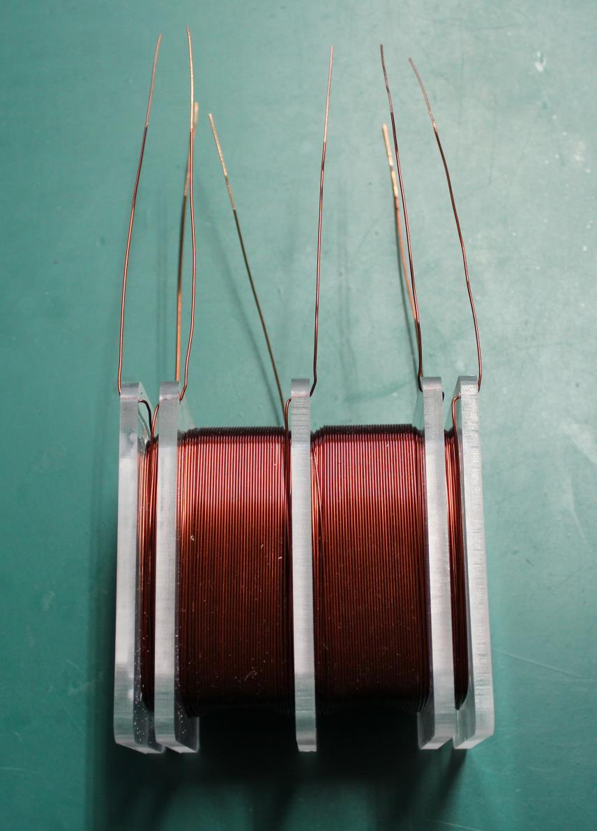
1 Guidelines to Bucking Coils. Lenz s Law Free Power Extraction. By Chris Sykes (hyiq.org)(emjunkie) Version Fig 1: Typical Bucking Power Output Coil, one configuration. Requirements: 1. At least two (2) Coils (Partnered Output Coils) must be used for each single Power Output Coil. 2. Each of the two power coils is best to have different direction of winding, relative to the Right Hand Rule applied to the Core. 3. The Magnetic Field MUST be thought of in a quite different way to the conventional thinking. More explained on this below. 4. Step Up techniques must be used, Power P = V x I or V2 Where R is the Resistance of the wire, I is the Current and V is the Voltage. I = P So this means that the Resistance of the R power Coil must also be taken into account, according to normal theory. Here, not so. 5. One input or Excitation coil per Power Coil. 6. Input or Excitation Coil is best to occupy only one half of the Power Coils Geometry. 7. The Bloch Walls of the Input/Excitation Coils is best not to overlap or exist in the same space as an artificial moving Bloch Wall. R


2 What does not Work: Circuit Equivalent:

3 Circuit Equivalent:
4 The above does not work primarily because the Magnetic Field as we understand it, is incomplete. The A Vector Potential and the Magnetic Field A, and Phi. Below Picture for illustratory purposes: Note: Arrows pointing to the Right indicate the Right Hand Rule as applied to the magnetic Field. Arrows Up and Down indicate the Bloch Wall Growing as a result of Time moving away from t=0. This will reverse as Field Maximum has been reached and Field decays as a result of I 2 R Factors.
5 I am going to take you on a ride in my Quantum Automobile! Plenty of room for all! Imagine the typical Solenoid, or Coil of Wire, Imagine the dynamic changes that occurs to each area at specific times throughout its operation. We are going to assume a 50Hz 50% Duty Cycle, typical AC Sine wave. We are going to park our Quantum Auto in the middle of the Core, absolute centre, where the Bloch wall will grow and decay with progression of the I 2 R factors resulting in the Magnetic Field that changes in strength over time. An observation can be made and the result is quite astounding! Observations: At t=0 we see nothing but particles and depending on the core material we may see residual Magnetic effects. Currently we are not too concerned about the residual magnetic Effects. As time moves from Zero we see an amazing effect! Looking up we can see a growing Toroidal Shaped Electric Field with Spin in the Clock Wise Direction moving away from us from our Observation Point. Looking down we can see a growing Toroidal Shaped Electric Field with Spin in the Counter Clock Wise Direction moving away from us from our Observation Point. Each Growing in intensity and at the same time moving away from us as the distance of the Bloch Wall grows in time. Now we move our Quantum Auto, and move it out to the perimeter looking sideways at the same Coil. What do we see now? The point of this Exercise! At this stage it is obvious that we have a difference in effects from our observation point. From outside we see two Toroidal electric fields that permeate all space growing and moving away from each other with, Equivalent Spin Direction, or what appears to be the same direction! From the Stand Point when we parked our Quantum Auto at the Centre of the Bloch Wall, we saw the opposite, Non Equivalent Spin Directions on each Toroidal Electric Field and each Toroidal Field moving away from each other. The point here is that Placement of coils is important, what a Coil sees as a result of its placement can change the entire operation of the device. Not only the placement but also the direction of turns is important if it is placed on the same core as the input coil. Turn Direction is the difference between a Dead Short in the device and not shorting the device and accessing another effect that some may not have seen before.
6 Experimental Results: I just want to say, the above is all from experimental results. It s not all conventional and to some, it is absolute blasphemy! But it s tried tested and true. We must understand the Magnetic Field as is shown above. Firstly, understanding the A Vector Potential and its partner Phi, is critical. A, is the Electric Component of the Magnetic Field and, Phi, is the Magnetic Component. The Right Hand Rule can be applied to the Field and an induced Current and Voltage can be predicted. The Right Hand Rule In Magnetics it is well known that the Current and the Magnetic Field follow the Right Hand Rule and the Voltage is in the reverse. The Bloch Wall It is very important to understand the Bloch Wall! Naturally Occurring and Naturally Induced.
7 I encourage experiments with the Bloch Wall. I have a small iron lamination with a hole in one end and I have cut it in half and made it into an arrow shape on the end, it s tied to a small piece of wire and I wave the Iron Lamination over the Bloch Wall. The Lamination will Jump over the Bloch Wall with extreme reluctance. It s as if there is an invisible wall of force that the Iron Lamination can only reluctantly pass. An example of both Naturally occurring and Naturally Induced Bloch Wall s is shown below: Red Arrows: Naturally Occurring Bloch Wall Orange Arrows: Naturally Induced Bloch Wall Another experiment: Take 10 or so Permanent Magnets of the same size. Check for the Bloch Wall on one Permanent Magnet, its size and location Then add another Permanent Magnet on top, in attraction mode. Then measure again the Size and Location of the Bloch Wall. Repeat by adding Magnets A similar experiment can be made by using a Variable DC Power Source and a high Inductance Coil, slowly turning up the Voltage Source. In this experiment, you will see the Bloch Wall grow, and also increase in intensity. However, its location won t move as is described above.
8 Induction and the Transforming Effect It s a very confusing subject. Science tells us Energy cannot be created or destroyed. But yet, at the same time we have Electricity Devices called Electric Generators! Electric Generators Generate Electrical Power and supply it to our Homes and Businesses and so on. Generate Definition: the production or creation of something. The definition of Generation Implies creating Energy from nothing, which Science tells us we cannot do. So is this subject already mystical Voodoo Science? Generator Definition: A person or thing that generates something. A routine that constructs other routines or subroutines using given parameters, for specific applications. A point, line, or surface regarded as moving and so notionally forming a line, surface, or solid. A dynamo or similar machine for converting mechanical energy into electricity. Here in lies a very serious problem! It s not bought up anywhere as far as I can tell. This definition does NOT explain how Mechanical Rotational Energy is converted into Electrical Energy on the Output Terminals. Energy in the form of Mechanical Rotation simply is not the actual causality of the Energy on the Output Terminals! E.G: I could spend all day rotating a Shaft and get not a single microwatt of Electrical Energy out of the shaft, only with the correct configuration of Conductors and Iron Stators and Rotors will I get output Power! So Mechanical Energy is NOT the Source of the Energy Generation! It is the silliest assumption I have ever heard in my entire life! I can t believe this is still an assumption that Science is still trying to lay out on people as the primary source of Conversion! See: Lenz s Law for more information. Mechanical Rotational Energy is only a partial requirement of Conventional Electrical Generators, because of Lenz s Law. Lenz s Law creates Resistance to Mechanical Energy in the Generator and more Mechanical Force is required to overcome this Resistance. See the Lenz s Law section for more information. The ideal configuration is, for, exactly one half of the Conductors in the Generator must experience an Electromagnetic Change opposite to the other half of the Conductors over Time. The equations are: emf = dphi dt = Induction via Flux Linking emf = Bvl = Induction via Flux Cutting
9 Where: dphi = a quantity of the Electromagnetic Field. dt = a quantity of time. B = Electromagnetic quantity. v = Velocity l = typically the Area of the Element sometimes is the length of the element in the case of a rotating loop for example. See: George I. Cohn - Electromagnetic Induction for more information. Put simply, a combination of the Conductors and the Electromagnetic Fields in Electric Generators separate Charge Carriers, positive one way, and Negative the other way, making one Terminal become Positively Charged and the other Negatively Charged. This will change depending on the polarity of the Induction Cycle inside the Electric Generator. This is simply a Sine Wave output. Chemical Charge Separation in Battery s and other devices like Solar Cell s work the same way. An Electric Transformer also works the same way. Induction is the Separation of Charge Carriers. How is Charge Separated In Generators and Transformers, it is Magnetic Force, the Lorentz Force, which is responsible for the Separation of Charge Carriers. I have done a few experiments to test and verify this. Red Arrow = Magnetic Field B. Blue Arrow = Force on the Electric Charge Yellow Arrow = Force on the Magnetic Field Green Arrow =.Velocity = Speed * Distance Travelled! Of either the Conductor or the Magnetic Field.

10 Lenz s law is the Result of drawing Current from the already Separated Charge, not the cause! A Moving Charge constitutes a Magnetic Field! Charges have to be available to move in the first place! I can t stress enough, how important it is to understand these principals and how they all fit together! References: URL: Covering the Lorentz Force! URL: Proving Induction Principals! URL: Highly Recommended! Step Up/Down Below is a simple diagram of a standard Step Down Transformer with a Globe (LA1): Without going into Transformer Theory and equations, Transformers (an Ideal Transformer) will work on Turns Ratio. Step Up and Step Down work on a ratio of each turn to each volt. A simple example follows: Input: 240Volts 240 Turns. 1 Volt per-turn. Output: 24 Volts 24 Turns. 1 Volt per-turn. This gives a Ratio of 10: 1, and is a Step Down Transformer. Power is also proportional, and as Voltage is stepped down, normally Current will increase. So in an Ideal Transformer no losses, Input Power = Output Power = (240Volts * 1 Amp) (24Volts * 10Amps). Of course this is in an Ideal Transformer with no Losses or other issues to contend with.
11 A lot of other factors come into Transformer Design like Wire Resistance and also Current Carrying Capabilities of the Wire and so on. The point I am getting to, is that these devices, use some Transformer Principals, but not others. Ideally, these devices work with a Step Up configuration. 1:3 is a common Ratio. That s one turn on the input to 3 turns on the output. Current, as you may think, is not stepped down as a result of the Voltage being stepped up. Floyd Sweet used a Step Up configuration of 1: 5 FB1: 48 Turns P1: 240 turns = 1:5 Ratio. This now famous Schematic is more clearly understood if we apply the concepts in this paper to Magnetics and to the VTA. By definition, the VTA IS a Triode, by definition it Gates the Vacuum, and as a result of the properties described in this paper it does amplify. I have studied Floyd Sweet and his VTA for some fifteen years. It took me around ten years to get an idea on what it was about and five or so years to experiment on.
12 I was given the original Lab Notes from the first Generation VTA, revision one and revision two, by an Anonymous source. In the Lab Notes the pages were labelled randomly and it appeared as if some pages were missing. I did not know for sure, but that s what it looked like. Please Click Here to see the original Lab Notes transcribed. "On rare occasions, Sweet saw this effect, called self-oscillation, occur in electric transformers" Ref: Jeane Manning: A New Physics for a New Energy Source / Free Energy - Making the Impossible Possible and "Sweet was also a transformer designer and expert, and he remarked that he had also observed specialized self-oscillation in certain transformers. " Ref: Energy From The Vacuum by Tom Bearden Sometimes the most obvious things can be the hardest to find. It s like the Car Keys that were on the bench all along and it took two hours to find them, and, you had already looked there several times! Then, once one finds something like this, it is easy to question its authenticity until a good understanding is achieved. Please keep the above picture in mind for the next section as it will become evident as to its significance soon. On the Internet, I had found a page that was supposed to be linked to Floyd Sweet but I was never able to verify its authenticity. Now I know that this page is either directly linked to Floyd Sweet or at least to the Technology that he worked on.
13 Here I show the page in its entirety: In the first drawing, we can clearly see the Partnered Secondary Coils! It is clearly obvious that there is a link here to the type of coils used as to the operation of the VTA as we know it to be after many years of research and experimentation. To date, the VTA is the most elegant device I have researched. Its size to output ratio is unbeatable for all other devices. The Generation Six VTA was in the order of 5000 Watts for a device that was not much bigger than the old fashioned Shoe Box.

14 The Flow of Current in a Wire when there is No Magnetic Field Experiment 1 The Circuit: Circuit Description:

15 Each Filar is 55.6mH individually, 55.6mH parallel and 0.231H Series connected. DC Coil Resistance is 3.8 Ohms each Filar and 1.9 Ohms parallel and 7.8 Ohms Series. Experiment 2 The Circuit: Circuit Description:
16 The Coil is BiFilar Wound Non Inductive Mode. Inductance Measurement on coil shows there is a residual Inductance of 0.24mH. DC Coil Resistance is 3.8 Ohms each Filar and 1.9 Ohms parallel and 7.8 Ohms Series. This is an expected behaviour for the Current in the Coil when the Inductance Changes. Here we have shown that for the same Resistance, (7.8 Ohms Series), that the Current Flow in the Conductor can move at a MUCH Faster rate even though the Resistance of the Conductor has NOT Changed! This proves that the Magnetic Field Slows the Charge Flow Rates dramatically. The Speed of the Flow Rate, 650 Micro Seconds (μs) compared to 75 milliseconds (ms) for charge time with the Magnetic Field.
17 What is the significance of this? Floyd Sweet said: Thus the duty factor of the copper changes. I 2 R Losses diminish and more charges drawn from the now coherent space field flow at a faster rate as current to the load. This means as more current is required by varying loads more feedback magnetomotive forces free more electrons from binding forces complimented by potential magnetic forces of the orientated, coherent space field. Thus a conductor that formerly had a temperature rise above ambient labelled as a factor of 10 would now operate at a temperature of 1.0. Thus the same gauge wire would carry 10 times more current at the same temperature. Also: As polarity may be maintained constant, that polarity of acceleration should be chosen so charges move at faster rates, lowering copper duty factor, and at the same time opening the gates wider so more coherent field entities may enter for the conversion process. It is the Magnetic Field itself that creates drag; it creates Friction on Electric Charge itself. It can be seen as heat in Conventional Electric Generators. What is Bi-Filar? According to Wikipedia: A bifilar coil is an electromagnetic coil that contains two closely spaced, parallel windings. In engineering, the word bifilar describes wire which is made of two filaments or strands. It is commonly used to denote special types of winding wire for transformers. This means that the term Bi-Filar should NOT be used for these types of Coil Arrangements, because, by definition, it s not correct!!! However, as is commonly done, terms are loosely thrown around. Unfortunately, this creates confusion. Tom Bearden Tom Bearden is, and always was, mostly right. The problem is that, his idea on the Conditioning of the Magnets is simply wrong. As I have seen to date, confusion sets in and it s hard to get it all right. I would like to quote from Tom Bearden:
18 "( 6 ) Investigative experiments to explore bucking EM force fields which neatly zero sum would have almost immediately revealed highly anomalous behaviour of materials and circuits. [Such simple investigations of zero-vector EM force field summation do not seem to appear in the Western literature at all, so far as can yet be established.]*** ***with the single exception of the Aharonov-Bohm effect, which has finally been proved after 27 years of controversy, and Hooper's work which was obscurely published. Something very much like that, together with quantum mechanical ideas, would have had to be applied to explain the operation of the Moray device. Note that every one of the suppositions above was available to any thorough Soviet search and the Soviet scientists certainly made the search, more massively and thoroughly than has ever been done before or since. Since the evidence is overwhelming that the Soviet scientists developed electrogravitation and scalar EM weapons, it seems logical that their search succeeded along these lines or similarly." Ref: "Now to some specific issues: Yes, my insight did keep growing. At first I took the results of experiments such as by Hooper, with opposing "ordinary waves". The effects of the core for the coils were a puzzle, but it seemed that sometimes the "opposing normal waves" would give some G effects, and more often they would not. What I did not realize for some time was that the longitudinal wave can be regarded as a superposed wave/antiwave, via a single SWZ wavepair. This agreed with Whittaker, and also now offered a sudden inspiration as to when we got the G effect and when not. We were dealing with four waves, not two, in the opposing ordinary waves. We had two opposing normal waves and two opposing antiwaves, with the wave/antiwave coupling. Two ordinary waves 180 degrees out of phase would certainly cancel (spatially) their amplitudes (as is well-known in RAM materials and structures) but would not cancel their energies. The two antiwaves would do likewise, spatially. The point then became, so what would happen in the time domain? Here we got a shocker. The two antiwaves would cancel each other's amplitude SPATIALLY, and would add energies. But looking at the action (energy x time) aspect, their energies exist in negative time! Well, this meant that the antiwave ACTION would come out negative, and would then cancel the added positive wave ACTION because? Ewt +? Eaw(-t) = 0. Therefore the sum of the whole mess was zero! Bummer! We wound up with everything just vanishing, wherein all the action (angular momentum) seemed to vanish. Well, this showed that the notion of simply having waves 180 degrees out of phase of itself would not give gravity effects. So that's why mostly the Hooper approach didn't seem to do much. But if one added nonlinear materials to the core, then one broke the linear cancellation. Once in a while, if one got it just right, one could get some spooky gravitational effects. So that was a real clue."
19 Ref: "I'd also like to point out the patents and work of Hooper. Hooper seems to be the only physicist who ever methodically investigated EM stresses, structuring of those stresses, and the gravitational implications of those stresses in the laboratory." Ref: Tom Bearden has shown diagrammatically what he was talking about above. Simply, two (2) Electromagnetic Waves, each opposing each other. A Wave and its Anti Wave, A1 and A2. Ref: I quote from Tom Bearden s Web Site: About seven years ago, the author was privileged to see and examine an invention of Mr. Floyd Sweet, that produced about 6 watts of electrical power from the vacuum itself. This remarkable device, which the author dubbed a vacuum triode, in a single unit utilized most of the scalar EM concepts the author had so painfully and slowly formulated over the years.
20 Sweet, a brilliant inventor with a remarkable knowledge of magnetics, had utilized barium ferrite magnets and special coils to produce a solid-state device that successfully tapped the vacuum energy. Please take note: special coils!!! Please note, for the purpose of this document, I have set the text special coils to bold and Underlined. I also would like to quote from the same page; As is well-known, a stress can be decomposed into opposing sets of forces. If the reader has not seen the video: Radionics at a Distance, please invest and watch this video. Portions of this video are by far the best work of Tom Bearden. In conjunction with the Whittaker Papers, as Tom Bearden has always stated, Wave and its Anti- Wave must be paired. Scalar Wave This term Scalar and how so many loosely use it, as if its magical, is very frustrating for me. Again it s a definition that s so loosely thrown around that not even 2 out of a million people could get the same answer!!! Let alone it being the right answer! Its slang terms for a Wave/Anti Wave pair. Definition: A Wave Pair (Wave / Anti-Wave) that Sum to Vector Zero. Stress Wave. A Wave that stands in Place. Very simple, no complexity to this. However, the Term Scalar was used in history to mean: (of a quantity) having only magnitude, not direction. As with all wave s, the Magnitude must change with Time if one is to define the Wave in the Cartesian Coordinate System. Simply, x, y and z relative to Time t. Lenz s Law Lenz s Law directly is responsible for the Conservation of energy, a long history is behind this, and without a doubt is a very interesting subject to study! What is Lenz s Law? Lenz s Law states: A law stating that the direction of an induced current is always such as to oppose the change in the circuit or the magnetic field that produces it. Perhaps the most famous Physicist of all time, Sir Richard Feynman said: So you see that the real energy change is the negative of the Mechanical Work and that s why I keep writing this as E Artificial. Because the true energy of the world is the negative of E Artificial in this case is μ. B I just want point out that difference in time, but that s just interesting.
21 Ref: V2 Ch15 Vector Potential 16:32 - Audio Lecture. So let s investigate Lenz s Law in some depth. Much of which is not in many Text Books simply because it s not properly understood! Loop A is the Bottom Loop and Loop B is the Top Loop. Loop A is our Primary Coil in our imaginary Transformer. Loop B is our Secondary Coil. If Loop B, our Secondary, is not connected to our Load, then Lenz s Law is not in effect, because no Current is flowing in Loop B, our Secondary. If Current is Flowing in our Secondary, the Current Flow is in the opposing direction to the Primary, this Creates a Magnetic Field in the opposing direction. Lenz s Law, is primarily Magnetic in Nature. It is the direct result of Current Flow in the Secondary Coil. This means, if we were able to turn off the Magnetic, but at the same time keep the Electric components, there would be no Reflected Power on the primary. In the above diagram, notice the Charge Carriers, moving in the opposing direction to each other. The Sine changes in the Induction Cycle in our Transformer and the Magnetic Field in our Secondary Changes Direction as a result. For this part of the cycle, the Magnetic Field is in reverse to the fore mentioned example. The direction of moving Charge Carriers also change direction. This is simply, a Sine Wave output on the Transformer Terminals. Important: Here we can see that when the Transformer is loaded, there is a NET ZERO Magnetic Field. This means the Ampere Turns on the primary are equal but opposite to the Ampere Turns on the secondary, or close to it. This is Tom Bearden s Whittaker Wave/Anti Wave. Where the Vector of each Magnetic Field sum s to ZERO!!! Please read on as this is not Tom Bearden s intended use! Our Transformer s Primary Coil sees Reflected Power (Lenz s law), this Reflected Power must be compensated for, because this reflected power = dphi, emphasising the Negative Sign, and as a dt
22 result the input Current must increase to support the Magnetic Field and push the Transformer through the BH Curve. For more information on the flow of Charge Carriers, see the Right Hand Rule. This Rule is without a doubt one of the most important rules in all of history. So now we have some idea on Lenz s Law. What can we do to try to eliminate or reduce this Secondary Induced Magnetic Field? Well surely by now the answers should be clear! This is simply, Tom Bearden s Wave / Anti-Wave, (Primary Electromagnetic Field) / (Secondary Electromagnetic Field)! The difference is that this is not what Tom Bearden was meaning when introducing this topic and is not the intended result of the uses of the Wave / Anti-Wave!!! In-fact this is why Tom Bearden says don t destroy the Di-Pole! At least the Primary Source Di-Pole. Do all the destroying you like on the Secondary Di-Pole! In-fact the Secondary Di-Pole is exactly where we need to work!!! A consequence of the law of conservation of energy is that a perpetual motion machine of the first kind cannot exist. That is to say, no system without an external energy supply can deliver an unlimited amount of energy to its surroundings. Ref: The Crazy thing is, the Atom is and always has been for all of eternity, without a Battery, and is still in continuous motion. So does NATURE agree with the statements contained in the Conservation of energy? The Atom is not an isolated system, however, and for that fact, a Generator is not either. Simply put, if Lenz s Law could be by passed, then every Generator on the planet could be a perpetual motion machine of the first kind! Isn t it silly how a Law of Nature can determine so much of history? Yes, the Conventional way of thinking, does limit us to Lenz s Law Restrictions in our Generators, but it s only because we have not been smart enough to allow this to change in history. As a result, we are still bound today by a law that is not valid under certain conditions. Question: Why is a Magnetic Field not detectable in every piece of matter in the universe? Answer: Because it s neighbour, and its neighbour and all the neighbours around them all CANCEL each other out. Does this sound familiar? Only when an Alignment process (Magnetisation) occurs, does all the Atoms Align, Spin Up and Spin Down, and there then exhibits a Magnetic Field in Matter!!!


23 Also, Noise Cancelation, it works the same way. An Anti-Wave cancels with a Vector Sum of Zero the wave in the opposite direction which can be considered the initial Wave. Wave/Anti-Wave pair. Remember, in this technology, this process can ONLY work, if Current is flowing in the Partnered Output Coils. Interestingly, the World s most efficient Generators are 98 99% efficient; this means that 100% of Rotational Shaft Energy, with a 1-2% loss in friction/heating and other losses, and the other % are the effects of Lenz Law creating Drag on the moving Rotor to generate Electrical Energy. A very simple Experiment. 1: Take a CRT Tube TV, turn it on and try to get a solid Colour on the screen. 2: Place one small permanent Magnet on the surface of the tube, securely. 3: Push another small Permanent Magnet, Poles Opposing, into the other small Permanent Magnet. Result: The Magnetic Field will be squeezed Nearly to Zero - NO MAGNETIC FIELD!!! So what does Work: Partnered Output Coils. Two coils working together. One input winding configured as described above and below to excite the Output Bucking Coils. Like was mentioned above and in more detail below, the area where the Bloch Wall moves in time must not align. This means as one set of Partnered Output Coils are brought together in Bucking mode the Bloch Wall of each Coil is stationary and a naturally induced Bloch Wall is induced between each of the two Bucking Output Coils. This naturally induced Bloch Wall moves in time with the Field. Where L1 and L2 are Partnered Output Coils the same as or similar to the shown Coil configuration: Note: Importantly, for this device to work, Current must be flowing in the Partnered Output Coils! As a result of knowing and understanding some simple basic principles and most importantly understanding them correctly, moves us into a new world of possibilities. After all, who wants to be
24 that person that abides by the stupid rules that someone set over 100 years ago when there is no longer any need to? Not me! These fore mentioned principals exist already in science; Noise Cancelation uses the very same rules and is dependent on these rules working for Noise Cancelation to be possible. Noise Cancelation is well known and well understood today. So, thus my question, why is it, that no one has thought to use the same principals in Power Generation? Essentially it is the same thing, an Electromagnetic Field growing and decaying in intensity ( dphi ) is the same thing in terms of Wave Cancelation or Noise Cancelation. dt This was my first device that shows the effects ( ): See Links Table below. And this was my second device: I seem to get a better result if the Input is resonated for example, LC Tank. I believe this is due to feed-back and or feed-forward in the coils. There seems to be a time constant in the Magnetic Fields of the Partnered Secondary Coils that appear to play a factor in the Operating Frequency.
25 Other Devices that have used this configuration There are many other devices that have shown this configuration of Output Coils. I will try to cover the best devices I have been able to find. As I have learned over my years of research, this technology is not new. Many people have come across or re-discovered from their own experiments and used this technology to access electrical energy without conventional restrictions and use it for useful purposes. This technology is not meant to be owned or controlled like Paul Raymond Jensen said. Thomas Henry Moray Ref: Thomas Henry Moray The Sea of Energy ~ Excerpts of technical factoids & illustrations of the Moray Radiant Energy Receiver. The tuning in consisted of stroking the end of a magnet across two metal projections protruding from what I referred to above as being a magnet. After tuning in for slightly more than 10 minutes the key was put on the operating post and the light appeared immediately... Ref: Thomas Henry Moray Click Here

26 Stanley Meyer s famous VIC Circuit - Water Fuel Cell Ref: Stan Meyer Tech Brief P. 83 Stan said; just add more turns on the Charging Chokes, so he was fully aware of this technology: Click Here See Minute: 38:16 Paul Raymond Jensen The UDT Transformer. Please read Paul Raymond Jensen s description of how his device works: Click Here.

27 Floyd Sparky Sweet - VTA Which with a partial re-draw is this:

28 Earl Koenig Electrical Circuit for Inductance Conductors, Transformers and Motors. Ref: US Patent: US Gennady Markov - Bidirectional Current Transformer

29 Alexander Frolov- A Toroidal Over-Unity Generator Andrey Melnichenko Ferromagnetic Free Energy Generation In the above device, one can see that the direction of turns is not reversed but results are still possible. Effectively the Magnetic Fields of each half of the device still oppose as a result of the Wiring Difference. For this reason, Andrey needs a rather large gap in his Cores so a short Circuit is not created in his device as a result of the A Vector Spins on the Core and the dynamic movement of them.

30 Mishail Free Energy Transformer Vladimir Utkin
31 Bill Alek SmartPAK. Loose Coupling All my experiments to date point to loosely coupled devices working better than tightly coupled devices. However in saying this, some of the fore-mentioned devices are tightly coupled. My best results have been from Loosely Coupled devices. For example; in the below device, I built, the Core Laminations were loosely coupled in the video.
32 I re-built this device and tightly coupled the Laminations, like a transformer, laying one over the other, lining the holes up and filling the space with another Lamination that was opposite to this on the other side. I was not able to make the device work the same. In the above device, I had a split core. The core was gapped by small plastic spacers. Much like as is shown in the Andrey Melnichenko device above but much smaller. Loose Coupling basically means, that the input is gapped ever so slightly, or that there is no direct path of Magnetic Coupling from input to output. For example, a Transformer is tightly coupled but some transformers can have a loosely coupled secondary path. An example of this is Paul Raymond Jensen UDT Transformer: You can see that the primary P1 is on the middle leg, the middle leg is gapped at the top by a small factor. This gives the device a Loose Coupling from Input to the output (S1) and feedback coils (S2).
33 Loose Coupling in Bill Alek s device is in the form of secondary set of cores on the output. Marked in Red is the primary Cores and the Arrows indicate the Flux Direction at t = random. The bigger Core is the secondary core and this is where the Opposing Fields or as Bill likes to put it, Opposing MMF lies, like in the following diagram. A requirement is, current MUST be flowing for this to work. If current is not flowing, the device will not work as is described. This is true for all the devices that use this technology.
34 Success/Failure I have spent many hundreds of hours, possibly more like many thousands of hours working on this technology, and today, I still do not have all the answers. For some reason, it is very hard to grasp fully, confusion very easily sets in and next thing one knows, you re not even working on this technology any more. I have never experienced anything quite like this type of confusion before. For every one device that works, expect 10 devices that don t. But, don t give up, keep trying. I have tried to the best of my ability to lay out here the basics. To explain how I see this technology working. In saying this, I may be wrong and it may work a totally different way. But I base all my information on experiment and to date, I have never seen an experiment that has been done several times show incorrect information. I think, to really make sense of this technology, one has to think in terms of Lenz s Law and how it can be by-passed. Or if one wants to look at this from another angle, like Paul Raymond Jensen said: An alternate explanation for the current gain in the UDT is to consider each secondary winding as acting as the primary winding for the other secondary winding when an output current is drawn because the two secondary windings generate geometrically opposing fields. Coil Winding and the Direction of the Turns IMPORTANT: This configuration is preferred for beginners! However, simply just taking a few standard Coils off the shelf may give you some promising results under certain configurations but BEWARE: The actual winding direction of one of the Partnered Secondary Coils is best to be physically wound in the opposing direction to the first. Simply flipping over one of the coils is NOT the same thing. Here are two Identical Coils, one flipped over from the first:

35 Clearly you can see here that the winding direction is not reversed. However, results can still be achieved in this configuration. In the next picture I show true Winding direction Change: Thus, the winding direction is now truly in reverse to the other. This is really important to understand as this can create a lot of confusion in its own right. Many people will ask, what, why are you saying this, its total rubbish and not valid for any real reason!!! I say, if only that person understood real Magnetics and real physics. Apply these ideas to this diagram:
36 Answers are clearly evident once one brings the time domain into account. Each Partnered Secondary Coil could be thought of as sitting in the space of each half of the above depicted core. North and South marked with N and an S, Bloch Wall in the middle and each part of the field (A Vector Potential) moving, one half up and the other half down. Again, it is critical that current be flowing in the Partnered Secondary Coils for this device to work. Floyd Sweet said: If the directions of the two signals are such that opposite H-fields cancel and E-fields add, an apparently steady E-Field will be created. The energy density of the fields remain as calculated above, but the value of the E-field will double from E to E. 2 And Inversely Similarly, if two signals flow through each other in such a way as to give the appearance of a steady magnetic field as a result of their E-field cancelling it is easily shown using the above equations to cancel out H and C. Where do I Start? I apologise to everyone here, I thought I had provided enough information in my videos and in my documents to start with. I made an assumption and a silly one at that. I am sorry! So, where and what would I recommend? First: Start at the Start! Very Important! Second: Low Cost Function Generator (Sine Wave) $14.99 URL: Click Here
37 Third: Small Low Cost Power Amplifier: $12.67 URL: Click Here Fourth: Coils, either you can wind your own or buy some: (2 at least) $15.50 each URL: Click Here
38 Fifth: Follow the following Circuits: To Start at the Start means to look at your device and feel what s its doing! It s the Magnetic Field that does the separation of Charges in this device! It is also responsible for encouraging excess Charge Carrier Separation! This means we need a reasonable Magnetic Field in each Coil! Output Configuration guide: The Magnetic Field of a coil is calculated: Magnetic Field (B) = Permeability (µ) x Turns Density (n) x Current (I) To get a reasonable Magnetic Field, one will need a good amount of turns and a reasonable Current. To increase the Current in the Output Circuit, one needs a Low Resistance, I have shown 10 Ohms but this can be decreased or increased as needed. It is the Magnetic Fields of each Coil that Interact with one another that is Important to make this work! The Magnetic Fields must be able to build, aloud time to build to a reasonable level! Don t Choke them Off!
39 I was lucky enough to have some C Cores from an old CRT TV that I managed to salvage! Click Here Sixth: Simple Experiments! Frequency is important. Do experiments to see what your Device likes and does not Like! Aim for the maximum Output! Most all of my devices have been best to run around 20Hz 600Hz Approximately! Remember: If you have No or Little Output then there is something wrong! Seven: Ask for Help! See the Forum Link Below! Please Note: The above are all recommendations! You must decide if these devices are what you need! If you wish to purchase items that will surface for later use then please feel free to look at other Items! If you already have some or all of these items in another form or make/model, then feel free to use them! Don t go and purchase items if you can make do or if you already have them! Use what you already have if you can. Key concepts to this Technology The most important key to this technology is simply, there MUST be TWO distinctly separate Coils, or Partnered Output Coils! This part is critical. The second part is simply that, each Output Coil MUST act in opposition to its Partnered Secondary! For this technology to work the Magnetic Field Component must cancel and the Electric Field Component must add! One Partnered Output Coil is a Generator (Charge Separation) for the other Partnered Output Coil. Like was shown above, in the Lenz s Law section, Magnetic Fields of each conductor oppose each other. This is because the Charge Carriers in the conductors each move in opposite directions. The same as how an Electric Generator and also how a Transformer works.
40 The only difference is, we have our Secondary Output Coils Generating currents simply by carrying their own currents which is the goal in the first place. This is Feedback!!! Magnetic Gating This section is a work in progress. However, in saying this, I think it is very important. We know that Stanley Meyer and also Floyd Sweet used Diodes in their devices. Also other devices Like Andrey Melnichenko s device use a Diode to switch on the Partnered Output Coils under one Polarity. Important: The Bore (Space inside the Coil) of one of the Partnered Output Coils will OPPOSE the Magnetic Field, Gating this space into an off Position for any Change in Magnetic Field. Stan Meyer s Diode marked in Red: Floyd Sweet s Stud Screw Diodes Marked in Red:
41 Also very important to note, Floyd Sweet used a HP 211A Square Wave Generator in his Generation two VTA. Shown below, also marked in Red: So Stan and Floyd (only in VTA Generation Two) both used Square Wave Input and also both used at least one diode. Is this just a coincidence or is there a very good reason for this? I think, by studying Stanley Meyer s diagram and a few simple experiments answers become clear. If the Diodes, or A Diode is not in place, then there is an issue where the input coil is Choked off and the Magnetic Field of the Primary Coil, as a result of this Choking Effect, cannot push the Core up to the knee in the BH Curve. However, this Technology does not move through Hysteresis (BH Curve). This is really important to understand. It best operates in and around the knee of t BH Curve. NOTE: This section only appears to be valid under some configurations!
42 Again Results can still be achieved without this realisation. However, much better results can be achieved if the Magnetic Field from the Primary Coil is NOT interfered with as it is charging. Please see the previous section The Flow of Current in a Wire when there is No Magnetic Field where I show the Charge Times and how this can be affected by the Magnetic Field. So, how does this work then? Well, once the Magnetic Field has reached its maximum, which is a result of Voltage applied to the Inductance, the Wire s Resistance and Voltage (Ohms Law), then just like in the Bedini works, the Magnetic Field Collapses when the DC input it switched off. The Polarity changes and the Collapsing Field switches on the Diode and then the Partnered Output Coils are used to do their Magic. And again, it s not Magic, it s very simple science if one thinks about it the right way. Concepts already well explained by distinguished people in science. History of Bucking Coils Through History, Bucking Coils have been most popularly been employed in the Audio field. The Humbucking Coil is possibly the oldest use of Bucking Coils that I have seen. Here are some basic examples: Ref: radiomuseum.org
43 Old Bell Ringers are also another old source of this type of technology. Old Bell Ringers may be possibly older than the Humbucking Coil. Here are some pictures:
44 It is interesting to note, Lester Hendershot used one of these in his device: The Hendershot Generator. Also similar to the Old Bell Ringers are the Tattoo Gun: Another source of the Bucking Coils is used in a Buck Transformer:
45 IMPORTANT: In the above examples, it is quite obvious, that just because the term Bucking is used, that these devices do not necessarily work as we require. Like I said before, expect 1 in 10 devices to work until a proper grasp of this Technology is developed. Once the right conditions are met, (all of which are described in this paper), then this Technology DOES WORK!!! The Magnetic Fields in the Partnered Output Coils To be clear, and to be correct, in all of this paper and all other places where we read about two Electromagnetic Waves, 180 degrees out of phase, cancelling, due to their Vector s summing to Zero, does not mean there is no longer any Magnetic Field Component! It simply means, that the Magnetic Field Components are confined to the space that the Electromagnetic Wave Pairs exist, or in our case, the space in which our Partnered Output Coils exist. There is still the A Vector Potential and the Magnetic Component, Phi, and there is still a Time Constant in the Charging of these Partnered Output Coils. One of the simple experiments I have done, is to have one Bobbin, with dual Coil Placements, wound with the Partnered Output Coil Configuration and spin up a Rotor with Permanent Magnets past the Partnered Output Coils. Result: No or next to no Lenz s Law and at the same time, Electricity is Generated or a better way to look at what is going on is Charge Separation. For a total Cancellation to occur, each Wire, in Each Partnered Output Coil must exist in exactly the same space as the other. Of Course, this is impossible. So Total Cancellation is also impossible. Also, the properties of the Wires must also be exactly the same. Slight imperfections in part, or parts of each wire will also reduce total Cancellation. When does an Input Coil become an Output Coil? I have to admit right up front, I believe I still don t quite fully understand this section, but I feel it needs to be mentioned.
46 Walt Rosenthal said: The VTA "likes" to always see a minimum load of 25 watts. There is a very good reason for this statement. With this technology, unlike conventional Transformer Technology, there are Feed Forwards and Feed Backs going on all the time. The Coils work TOGETHER in such a fashion to assist in operations. More so, when properly running with the right load. Not to say this Technology is Load dependant, because to date I have not seen any real issues with the type of load. But I mean that the load must be selected such that the operations of the coils allow for enough Feed Back and Feed Forward. Example: Our three coils, Primary input Coil, and Partnered Secondary Output Coils (Two Coils working together) once in operation, the current from the Partnered Output Coils can feed back via confined Magnetic Fields, which as we know, the time rate of change of Magnetic Fields creates Charge Carrier Separation in a conductor in its approximation, as a result, the Input Coils Impedance is increased dramatically. This brings back the input current and as a result the input power is dramatically lowered. One could imagine this as a conventional Transformer with a Primary and a Secondary. Our Primary is driven with typical Mains power. We load the transformer. Our Load just so happens to be another Power Source. This power Source is adjustable Power and Frequency so we can get a phase Lock on the input. Then we turn up the secondary and at a point, the input power is reduced simply because we have a source of power returning back to our Transformer with the right Phase and Power levels to increase the impedance of the Input Coil. This will in-turn lower the Input power. So we can now see why the Load is important. Enough Current must be flowing in the Partnered Output coils to operate. Once operating correctly, the input power is reduced. This is a simple case of applying Ohms Law, V 2 Where: V = Voltage R = Resistance The product of this equation is Power: P Current: I V: Voltage normally = Power unless there is a Phase Angle difference between the two, Current is what creates the Magnetic Field. With no Flow of Charge Carriers, there can be no Magnetic Field. With No Magnetic Field there can be No Charge Separation. Again I stress, the Magnetic Field is the A Vector Potential, and Phi, the Magnetic Flux. So we can have a Vector Cancelation, but these components still exist in the Coils Immediate Space. R The Magnetic Field It should be realised that ANY system that uses Electric or Magnetic Fields are Open Systems.
47 Meaning they are directly connected to the Aether!!! Nature, Equilibrium, will always try to bring any system out of equilibrium, back into equilibrium, or else the Universe would fly to pieces, nothing would exist for long. Thus, it is Nature that gives us things like the Magnetic Field, to bring moving Charge Carriers back to a state of Equilibrium. When I started researching Free Energy and Anti-Gravity, I was lucky enough to see a direct connection to the Magnetic Components and Free Energy, that there was a direct link. It appeared as if Free Energy came from the Magnetic Component and not the Electric Component, that some where there laid a totally new source of totally different type of Energy not many had seen before and that it was amazingly powerful. Well, I found out that only some of this is correct. It took me a long time to see that there was no new form of Energy. That it is an adaptation of the already known energy we have today, but just that some of its characteristics are different because of the conditions that it is transformed under are different. Let s look at an example: Conventionally, just as there is a Time Constant to Charge a Conductor, there is a Time Constant to Generate, or a better description, to Separate Charge Carriers in a Conductor. All the same rules apply, Impedance, Inductance, Resistance (which sort of falls under the Impedance field) and Time. Take a big Coil, big Magnet, a light as a Load, and swipe it past the Coil such to Light the light. It takes time to separate the charges and as a result this time can be seen in the Lighting of the load. It takes time to Light the light due to the Impedance of the Coil.
48 Inversely, In this technology, once applied correctly, as is shown above in the section The Flow of Current in a Wire when there is No Magnetic Field, because we have reduced the external influences of the Magnetic Field, we can now see these above mentioned factors are reduced so low that they are negligible to the system. As a result, the human eye will see the Light, Light nearly immediately due to the Coils Impedance being reduced right down. The Control of Magnetic Fields opens doors to new possibilities in Science that has not been fully realised to date. The use of Magnetic Fields to do amazing things is only now starting to be realised in simple devices. Arguments can be made, Chicken or the Egg but once one realises that this is a mute argument and actually an invalid argument then one is able to move into the future of new possibilities in science. Experiment: Take a conventional Automotive Alternator. Install on a Rig along with an Electric Motor. Drive the Automotive Alternator with the Electric Motor Only input is mechanical in the form of Rotation to the Alternator Shaft! Question: Is it possible to get an Output with No Extra Input to the Alternator? Answer: Yes Result: By connecting the Field Coil on the Alternator in such a way, either in a short circuit, or connected in series with the output Coils, enough Feed Back is produced to get an Electrical Output on the Output Terminals. Not Free Energy, but this shows that Feed Back Techniques can excite the Coils and Magnetic Fields can Manifest in the Device with no further Input! The Magnetic Field can be made to Support Itself! ONLY because of Lenz Law, Resistive Mechanical Force is applied on the Shaft in Opposition to the applied Input from the Electric Motor! Lenz's Law is Only a Result of the Electrical Output, NOT the Cause!!! In-creasing the Output Potential It is possible in some configurations, to increase the output potential simply by adding Uniform magnetic Fields. Either one or two. To is better to increase the uniformity of the Field. More Work and Investigation
49 Frequency Response for the best output is hard to determine. There appears to be many factors responsible for the best frequency of operation. There is a lot I am still investigating here. I don t have all the answers yet. Summary The Free Energy Future is here NOW! Learn it, use it, share it! After all, it s been here for a LONG time, the problem is, the world is consumed by greed, selfishness, arrogance and out right Parasitic individuals for which there is no cure. Good People need to take the steering wheel of life with both hands, with a grasp like its life and death, and get back on track before it all ends in a train wreck! Knowledge and Applying Knowledge is Freedom!!! Definition Table: Term: Partnered Output Coils Scalar Wave Reflected Power SWZ Definition: A set of two (2) Coils that are configured to work together A Wave Pair (Wave / Anti-Wave) that Sum to Vector Zero. Stress Wave. A Wave that stands in Place. Power that is reflected back on the source, the negative of the source. Stoney/Whittaker/Ziolkowski (SWZ) methodology Credit So many people deserve credit. All of the fore-mentioned people and so many more. Clemente Figuera, T Henry Moray, Lester Hendershot, Raymond Kromrey, Stanley Meyer, Paul Raymond Jensen, Floyd Sweet, Earl Koenig, Alexander Frolov, Andrey Melnichenko, sergdo, Alexander Mishin, Mishail1971, Bill Alek, and many hundreds more. Tom Bearden, John Bedini, and many that do not wish to be mentioned! You deserve credit also for reading this document and taking part in this revolution, the Awakening. Links Term: Doc Updates My first Device Second Device AuroraTek demo AuroraTek demo Forum Help: Definition: thanks Russ Sterling s interview and NOT: This document is not complete and more information will be coming in the next version. Check Doc Updates above for new Versions.
DIRECT CURRENT GENERATORS
 DIRECT CURRENT GENERATORS Revision 12:50 14 Nov 05 INTRODUCTION A generator is a machine that converts mechanical energy into electrical energy by using the principle of magnetic induction. This principle
Motor Fundamentals. DC Motor
 Motor Fundamentals Before we can examine the function of a drive, we must understand the basic operation of the motor. It is used to convert the electrical energy, supplied by the controller, to mechanical
PS-6.2 Explain the factors that determine potential and kinetic energy and the transformation of one to the other.
 PS-6.1 Explain how the law of conservation of energy applies to the transformation of various forms of energy (including mechanical energy, electrical energy, chemical energy, light energy, sound energy,
The purposes of this experiment are to test Faraday's Law qualitatively and to test Lenz's Law.
 260 17-1 I. THEORY EXPERIMENT 17 QUALITATIVE STUDY OF INDUCED EMF Along the extended central axis of a bar magnet, the magnetic field vector B r, on the side nearer the North pole, points away from this
Inductors. AC Theory. Module 3
 Module 3 AC Theory What you ll learn in Module 3. Section 3.1 Electromagnetic Induction. Magnetic Fields around Conductors. The Solenoid. Section 3.2 Inductance & Back e.m.f. The Unit of Inductance. Factors
Magnetic Fields and Their Effects
 Name Date Time to Complete h m Partner Course/ Section / Grade Magnetic Fields and Their Effects This experiment is intended to give you some hands-on experience with the effects of, and in some cases
Linear DC Motors. 15.1 Magnetic Flux. 15.1.1 Permanent Bar Magnets
 Linear DC Motors The purpose of this supplement is to present the basic material needed to understand the operation of simple DC motors. This is intended to be used as the reference material for the linear
ElectroMagnetic Induction. AP Physics B
 ElectroMagnetic Induction AP Physics B What is E/M Induction? Electromagnetic Induction is the process of using magnetic fields to produce voltage, and in a complete circuit, a current. Michael Faraday
Force on Moving Charges in a Magnetic Field
 [ Assignment View ] [ Eðlisfræði 2, vor 2007 27. Magnetic Field and Magnetic Forces Assignment is due at 2:00am on Wednesday, February 28, 2007 Credit for problems submitted late will decrease to 0% after
1. The diagram below represents magnetic lines of force within a region of space.
 1. The diagram below represents magnetic lines of force within a region of space. 4. In which diagram below is the magnetic flux density at point P greatest? (1) (3) (2) (4) The magnetic field is strongest
Edmund Li. Where is defined as the mutual inductance between and and has the SI units of Henries (H).
.") INDUCTANCE MUTUAL INDUCTANCE If we consider two neighbouring closed loops and with bounding surfaces respectively then a current through will create a magnetic field which will link with as the flux passes
INDUCTANCE MUTUAL INDUCTANCE If we consider two neighbouring closed loops and with bounding surfaces respectively then a current through will create a magnetic field which will link with as the flux passes
DC GENERATOR THEORY. LIST the three conditions necessary to induce a voltage into a conductor.
 DC Generators DC generators are widely used to produce a DC voltage. The amount of voltage produced depends on a variety of factors. EO 1.5 LIST the three conditions necessary to induce a voltage into
Chapter 22: Electric motors and electromagnetic induction
 Chapter 22: Electric motors and electromagnetic induction The motor effect movement from electricity When a current is passed through a wire placed in a magnetic field a force is produced which acts on
Objectives. Capacitors 262 CHAPTER 5 ENERGY
 Objectives Describe a capacitor. Explain how a capacitor stores energy. Define capacitance. Calculate the electrical energy stored in a capacitor. Describe an inductor. Explain how an inductor stores energy.
Line Reactors and AC Drives
 Line Reactors and AC Drives Rockwell Automation Mequon Wisconsin Quite often, line and load reactors are installed on AC drives without a solid understanding of why or what the positive and negative consequences
Simple Analysis for Brushless DC Motors Case Study: Razor Scooter Wheel Motor
 Simple Analysis for Brushless DC Motors Case Study: Razor Scooter Wheel Motor At first glance, a brushless direct-current (BLDC) motor might seem more complicated than a permanent magnet brushed DC motor,
Understanding the Alternator
 http://www.autoshop101.com THIS AUTOMOTIVE SERIES ON ALTERNATORS HAS BEEN DEVELOPED BY KEVIN R. SULLIVAN PROFESSOR OF AUTOMOTIVE TECHNOLOGY AT SKYLINE COLLEGE SAN BRUNO, CALIFORNIA ALL RIGHTS RESERVED
Introduction to Electricity & Magnetism. Dr Lisa Jardine-Wright Cavendish Laboratory
 Introduction to Electricity & Magnetism Dr Lisa Jardine-Wright Cavendish Laboratory Examples of uses of electricity Christmas lights Cars Electronic devices Human body Electricity? Electricity is the presence
Chapter 7. Magnetism and Electromagnetism ISU EE. C.Y. Lee
 Chapter 7 Magnetism and Electromagnetism Objectives Explain the principles of the magnetic field Explain the principles of electromagnetism Describe the principle of operation for several types of electromagnetic
Power Supplies. 1.0 Power Supply Basics. www.learnabout-electronics.org. Module
 Module 1 www.learnabout-electronics.org Power Supplies 1.0 Power Supply Basics What you ll learn in Module 1 Section 1.0 Power Supply Basics. Basic functions of a power supply. Safety aspects of working
Principles of Adjustable Frequency Drives
 What is an Adjustable Frequency Drive? An adjustable frequency drive is a system for controlling the speed of an AC motor by controlling the frequency of the power supplied to the motor. A basic adjustable
8 Speed control of Induction Machines
 8 Speed control of Induction Machines We have seen the speed torque characteristic of the machine. In the stable region of operation in the motoring mode, the curve is rather steep and goes from zero torque
Digital Energy ITI. Instrument Transformer Basic Technical Information and Application
 g Digital Energy ITI Instrument Transformer Basic Technical Information and Application Table of Contents DEFINITIONS AND FUNCTIONS CONSTRUCTION FEATURES MAGNETIC CIRCUITS RATING AND RATIO CURRENT TRANSFORMER
Odyssey of the Mind Technology Fair. Simple Electronics
 Simple Electronics 1. Terms volts, amps, ohms, watts, positive, negative, AC, DC 2. Matching voltages a. Series vs. parallel 3. Battery capacity 4. Simple electronic circuit light bulb 5. Chose the right
AC generator theory. Resources and methods for learning about these subjects (list a few here, in preparation for your research):
:") AC generator theory This worksheet and all related files are licensed under the Creative Commons Attribution License, version 1.0. To view a copy of this license, visit http://creativecommons.org/licenses/by/1.0/,
AC generator theory This worksheet and all related files are licensed under the Creative Commons Attribution License, version 1.0. To view a copy of this license, visit http://creativecommons.org/licenses/by/1.0/,
Students will investigate the characteristics of electromagnetism and then use what they learn to plan and conduct an experiment on electromagnets.
 Electromagnetic Power! Lesson Overview Students will investigate the characteristics of electromagnetism and then use what they learn to plan and conduct an experiment on electromagnets. Suggested Grade
Power Electronics. Prof. K. Gopakumar. Centre for Electronics Design and Technology. Indian Institute of Science, Bangalore.
 Power Electronics Prof. K. Gopakumar Centre for Electronics Design and Technology Indian Institute of Science, Bangalore Lecture - 1 Electric Drive Today, we will start with the topic on industrial drive
5. Measurement of a magnetic field
 H 5. Measurement of a magnetic field 5.1 Introduction Magnetic fields play an important role in physics and engineering. In this experiment, three different methods are examined for the measurement of
(Refer Slide Time: 2:03)
") Control Engineering Prof. Madan Gopal Department of Electrical Engineering Indian Institute of Technology, Delhi Lecture - 11 Models of Industrial Control Devices and Systems (Contd.) Last time we were
Control Engineering Prof. Madan Gopal Department of Electrical Engineering Indian Institute of Technology, Delhi Lecture - 11 Models of Industrial Control Devices and Systems (Contd.) Last time we were
Lab 8: DC generators: shunt, series, and compounded.
 Lab 8: DC generators: shunt, series, and compounded. Objective: to study the properties of DC generators under no-load and full-load conditions; to learn how to connect these generators; to obtain their
THE LUCAS C40 DYNAMO & ITS ARMATURE.
 THE LUCAS C40 DYNAMO & ITS ARMATURE. H. Holden, March 2011. The Dynamo as a DC generating machine was used extensively in the pre- Alternator era, from the early 1900 s up to the late 1960 s and early
GenTech Practice Questions
 GenTech Practice Questions Basic Electronics Test: This test will assess your knowledge of and ability to apply the principles of Basic Electronics. This test is comprised of 90 questions in the following
H ello, I ll be demonstrating
 Magnetic Pulser MP6 How-to Video Transcription H ello, I ll be demonstrating the use of the SOTA Magnetic Pulser. The latest model is shown here, our Model MP6. Before we get started I just want to draw
SYNCHRONOUS MACHINES
 SYNCHRONOUS MACHINES The geometry of a synchronous machine is quite similar to that of the induction machine. The stator core and windings of a three-phase synchronous machine are practically identical
AP1 Electricity. 1. A student wearing shoes stands on a tile floor. The students shoes do not fall into the tile floor due to
 1. A student wearing shoes stands on a tile floor. The students shoes do not fall into the tile floor due to (A) a force of repulsion between the shoes and the floor due to macroscopic gravitational forces.
13 ELECTRIC MOTORS. 13.1 Basic Relations
 13 ELECTRIC MOTORS Modern underwater vehicles and surface vessels are making increased use of electrical actuators, for all range of tasks including weaponry, control surfaces, and main propulsion. This
E/M Experiment: Electrons in a Magnetic Field.
 E/M Experiment: Electrons in a Magnetic Field. PRE-LAB You will be doing this experiment before we cover the relevant material in class. But there are only two fundamental concepts that you need to understand.
How to Turn an AC Induction Motor Into a DC Motor (A Matter of Perspective) Steve Bowling Application Segments Engineer Microchip Technology, Inc.
 Steve Bowling Application Segments Engineer Microchip Technology, Inc.") 1 How to Turn an AC Induction Motor Into a DC Motor (A Matter of Perspective) Steve Bowling Application Segments Engineer Microchip Technology, Inc. The territory of high-performance motor control has
1 How to Turn an AC Induction Motor Into a DC Motor (A Matter of Perspective) Steve Bowling Application Segments Engineer Microchip Technology, Inc. The territory of high-performance motor control has
The DC Motor/Generator Commutation Mystery. Commutation and Brushes. DC Machine Basics
 The DC Motor/Generator Commutation Mystery One small, yet vital piece of the DC electric motor puzzle is the carbon brush. Using the correct carbon brush is a key component for outstanding motor life,
STUDY GUIDE: ELECTRICITY AND MAGNETISM
 319 S. Naperville Road Wheaton, IL 60187 www.questionsgalore.net Phone: (630) 580-5735 E-Mail: [email protected] Fax: (630) 580-5765 STUDY GUIDE: ELECTRICITY AND MAGNETISM An atom is made of three
Chen. Vibration Motor. Application note
 Vibration Motor Application note Yangyi Chen April 4 th, 2013 1 Table of Contents Pages Executive Summary ---------------------------------------------------------------------------------------- 1 1. Table
Chapter 22: Vladimir Utkin and Lenz s Law
 A Practical Guide to Free-Energy Devices Author: Patrick J. Kelly Chapter 22: Vladimir Utkin and Lenz s Law Vladimir Utkin is a well-respected Russian researcher who has kindly shared his insights into
Lab 3 - DC Circuits and Ohm s Law
 Lab 3 DC Circuits and Ohm s Law L3-1 Name Date Partners Lab 3 - DC Circuits and Ohm s Law OBJECTIES To learn to apply the concept of potential difference (voltage) to explain the action of a battery in
Eðlisfræði 2, vor 2007
 [ Assignment View ] [ Print ] Eðlisfræði 2, vor 2007 30. Inductance Assignment is due at 2:00am on Wednesday, March 14, 2007 Credit for problems submitted late will decrease to 0% after the deadline has
Magnetism Basics. Magnetic Domains: atomic regions of aligned magnetic poles Random Alignment Ferromagnetic Alignment. Net Effect = Zero!
 Magnetism Basics Source: electric currents Magnetic Domains: atomic regions of aligned magnetic poles Random Alignment Ferromagnetic Alignment Net Effect = Zero! Net Effect = Additive! Bipolar: all magnets
DC generator theory. Resources and methods for learning about these subjects (list a few here, in preparation for your research):
:") DC generator theory This worksheet and all related files are licensed under the Creative Commons Attribution License, version 1.0. To view a copy of this license, visit http://creativecommons.org/licenses/by/1.0/,
DC generator theory This worksheet and all related files are licensed under the Creative Commons Attribution License, version 1.0. To view a copy of this license, visit http://creativecommons.org/licenses/by/1.0/,
Application Note. So You Need to Measure Some Inductors?
 So You Need to Measure Some nductors? Take a look at the 1910 nductance Analyzer. Although specifically designed for production testing of inductors and coils, in addition to measuring inductance (L),
Fundamentals of radio communication
 Fundamentals of radio communication This worksheet and all related files are licensed under the Creative Commons Attribution License, version 1.0. To view a copy of this license, visit http://creativecommons.org/licenses/by/1.0/,
CONSTRUCTING A VARIABLE POWER SUPPLY UNIT
 CONSTRUCTING A VARIABLE POWER SUPPLY UNIT Building a power supply is a good way to put into practice many of the ideas we have been studying about electrical power so far. Most often, power supplies are
Magnetic Field of a Circular Coil Lab 12
 HB 11-26-07 Magnetic Field of a Circular Coil Lab 12 1 Magnetic Field of a Circular Coil Lab 12 Equipment- coil apparatus, BK Precision 2120B oscilloscope, Fluke multimeter, Wavetek FG3C function generator,
A Practical Guide to Free Energy Devices
 A Practical Guide to Free Energy Devices Electrolysis Patents No. 16: Last updated: 30th September 2006 Author: Patrick J. Kelly The major difficulty in using Stan s low-current Water Fuel Cell (recently
Interference in the ECG and its elimination
 Interference in the ECG and its elimination General points The signal voltages in ECG recording are known to be very small and are in the millivolt range, i.e. they have amplitudes of only a few thousands
Drive circuit basics + V. τ e. Industrial Circuits Application Note. Winding resistance and inductance
 ndustrial Circuits Application Note Drive circuit basics For a given size of a stepper motor, a limited space is available for the windings. n the process of optimizing a stepper motor drive system, an
Energy Saving systems for Induction motors.
 Energy Saving systems for Induction motors. Are they a sham? Do they work? There seems to be a resurgence in interest in the Nola energy saving algorithm for induction motors, with a number of manufacturers
An equivalent circuit of a loop antenna.
 3.2.1. Circuit Modeling: Loop Impedance A loop antenna can be represented by a lumped circuit when its dimension is small with respect to a wavelength. In this representation, the circuit parameters (generally
Induction Motor Theory
 PDHonline Course E176 (3 PDH) Induction Motor Theory Instructor: Jerry R. Bednarczyk, P.E. 2012 PDH Online PDH Center 5272 Meadow Estates Drive Fairfax, VA 22030-6658 Phone & Fax: 703-988-0088 www.pdhonline.org
Inductors. Resources and methods for learning about these subjects (list a few here, in preparation for your research):
:") Inductors This worksheet and all related files are licensed under the Creative Commons Attribution License, version 1.0. To view a copy of this license, visit http://creativecommons.org/licenses/by/1.0/,
Inductors This worksheet and all related files are licensed under the Creative Commons Attribution License, version 1.0. To view a copy of this license, visit http://creativecommons.org/licenses/by/1.0/,
Lab 14: 3-phase alternator.
 Lab 14: 3-phase alternator. Objective: to obtain the no-load saturation curve of the alternator; to determine the voltage regulation characteristic of the alternator with resistive, capacitive, and inductive
Selecting IHLP Composite Inductors for Non-Isolated Converters Utilizing Vishay s Application Sheet
 VISHAY DALE www.vishay.com Magnetics Selecting IHLP Composite Inductors for Non-Isolated Converters INTRODUCTION This application note will provide information to assist in the specification of IHLP composite
Impedance Matching and Matching Networks. Valentin Todorow, December, 2009
 Impedance Matching and Matching Networks Valentin Todorow, December, 2009 RF for Plasma Processing - Definition of RF What is RF? The IEEE Standard Dictionary of Electrical and Electronics Terms defines
Eðlisfræði 2, vor 2007
 [ Assignment View ] [ Pri Eðlisfræði 2, vor 2007 28. Sources of Magnetic Field Assignment is due at 2:00am on Wednesday, March 7, 2007 Credit for problems submitted late will decrease to 0% after the deadline
Lecture - 4 Diode Rectifier Circuits
 Basic Electronics (Module 1 Semiconductor Diodes) Dr. Chitralekha Mahanta Department of Electronics and Communication Engineering Indian Institute of Technology, Guwahati Lecture - 4 Diode Rectifier Circuits
Induced voltages and Inductance Faraday s Law
 Induced voltages and Inductance Faraday s Law concept #1, 4, 5, 8, 13 Problem # 1, 3, 4, 5, 6, 9, 10, 13, 15, 24, 23, 25, 31, 32a, 34, 37, 41, 43, 51, 61 Last chapter we saw that a current produces a magnetic
E. K. A. ADVANCED PHYSICS LABORATORY PHYSICS 3081, 4051 NUCLEAR MAGNETIC RESONANCE
 E. K. A. ADVANCED PHYSICS LABORATORY PHYSICS 3081, 4051 NUCLEAR MAGNETIC RESONANCE References for Nuclear Magnetic Resonance 1. Slichter, Principles of Magnetic Resonance, Harper and Row, 1963. chapter
Magnetic Fields. I. Magnetic Field and Magnetic Field Lines
 Magnetic Fields I. Magnetic Field and Magnetic Field Lines A. The concept of the magnetic field can be developed in a manner similar to the way we developed the electric field. The magnitude of the magnetic
Chapter 19 Operational Amplifiers
 Chapter 19 Operational Amplifiers The operational amplifier, or op-amp, is a basic building block of modern electronics. Op-amps date back to the early days of vacuum tubes, but they only became common
Building the HVPS High Voltage Power Supply
 Introduction Building the HVPS High Voltage Power Supply Voltages higher than the LVPS provides kilovolts are needed in later experiments to get strong electric fields and to generate microwaves. The high-voltage
MEASURING INSTRUMENTS. By: Nafees Ahmed, Asstt, Prof, EE Deptt, DIT, Dehradun
 MEASURING INSTRUMENTS By: Nafees Ahmed, Asstt, Prof, EE Deptt, DIT, Dehradun MEASURING INSTRUMENTS The device used for comparing the unknown quantity with the unit of measurement or standard quantity is
ECEN 1400, Introduction to Analog and Digital Electronics
 ECEN 1400, Introduction to Analog and Digital Electronics Lab 4: Power supply 1 INTRODUCTION This lab will span two lab periods. In this lab, you will create the power supply that transforms the AC wall
Aircraft Electrical System
 Chapter 9 Aircraft Electrical System Introduction The satisfactory performance of any modern aircraft depends to a very great degree on the continuing reliability of electrical systems and subsystems.
Ampere's Law. Introduction. times the current enclosed in that loop: Ampere's Law states that the line integral of B and dl over a closed path is 0
 1 Ampere's Law Purpose: To investigate Ampere's Law by measuring how magnetic field varies over a closed path; to examine how magnetic field depends upon current. Apparatus: Solenoid and path integral
Slide 1 / 26. Inductance. 2011 by Bryan Pflueger
 Slide 1 / 26 Inductance 2011 by Bryan Pflueger Slide 2 / 26 Mutual Inductance If two coils of wire are placed near each other and have a current passing through them, they will each induce an emf on one
12. Transformers, Impedance Matching and Maximum Power Transfer
 1 1. Transformers, Impedance Matching and Maximum Power Transfer Introduction The transformer is a device that takes AC at one voltage and transforms it into another voltage either higher or lower than
Energy, Work, and Power
 Energy, Work, and Power This worksheet and all related files are licensed under the Creative Commons Attribution License, version 1.0. To view a copy of this license, visit http://creativecommons.org/licenses/by/1.0/,
Electromagnetism Laws and Equations
 Electromagnetism Laws and Equations Andrew McHutchon Michaelmas 203 Contents Electrostatics. Electric E- and D-fields............................................. Electrostatic Force............................................2
Basic circuit troubleshooting
 Basic circuit troubleshooting This worksheet and all related files are licensed under the Creative Commons Attribution License, version 1.0. To view a copy of this license, visit http://creativecommons.org/licenses/by/1.0/,
Iron Powder Cores for Switchmode Power Supply Inductors. by: Jim Cox
 HOME APPLICATION NOTES Iron Powder Cores for Switchmode Power Supply Inductors by: Jim Cox Purpose: The purpose of this application note is to cover the properties of iron powder as a magnetic core material
Objectives 200 CHAPTER 4 RESISTANCE
 Objectives Explain the differences among conductors, insulators, and semiconductors. Define electrical resistance. Solve problems using resistance, voltage, and current. Describe a material that obeys
Mapping the Magnetic Field
 I Mapping the Magnetic Field Mapping the Magnetic Field Vector Fields The electric field, E, and the magnetic field, B, are two examples of what are termed vector fields, quantities which have both magnitude
Coupled Inductors. Introducing Coupled Inductors
 Coupled Inductors From power distribution across large distances to radio transmissions, coupled inductors are used extensively in electrical applications. Their properties allow for increasing or decreasing
Power Quality Paper #3
 The Effect of Voltage Dips On Induction Motors by: M D McCulloch 1. INTRODUCTION Voltage depressions caused by faults on the system affect the performance of induction motors, in terms of the production
Synchronous motor. Type. Non-excited motors
 Synchronous motor A synchronous electric motor is an AC motor in which the rotation rate of the shaft is synchronized with the frequency of the AC supply current; the rotation period is exactly equal to
BASIC ELECTRONICS AC CIRCUIT ANALYSIS. December 2011
 AM 5-202 BASIC ELECTRONICS AC CIRCUIT ANALYSIS December 2011 DISTRIBUTION RESTRICTION: Approved for Pubic Release. Distribution is unlimited. DEPARTMENT OF THE ARMY MILITARY AUXILIARY RADIO SYSTEM FORT
LR Phono Preamps. Pete Millett ETF.13. [email protected]
 LR Phono Preamps Pete Millett ETF.13 [email protected] Agenda A bit about me Part 1: What is, and why use, RIAA? Grooves on records The RIAA standard Implementations of RIAA EQ networks and preamps
ELECTRON SPIN RESONANCE Last Revised: July 2007
 QUESTION TO BE INVESTIGATED ELECTRON SPIN RESONANCE Last Revised: July 2007 How can we measure the Landé g factor for the free electron in DPPH as predicted by quantum mechanics? INTRODUCTION Electron
OHM S LAW AND RESISTANCE
 OHM S LAW AND RESISTANCE Resistance is one of the basic principles of Ohm s law, and can be found in virtually any device used to conduct electricity. Georg Simon Ohm was a German physicist who conducted
ENERGY TRANSFER SYSTEMS AND THEIR DYNAMIC ANALYSIS
 ENERGY TRANSFER SYSTEMS AND THEIR DYNAMIC ANALYSIS Many mechanical energy systems are devoted to transfer of energy between two points: the source or prime mover (input) and the load (output). For chemical
VOLTAGE REGULATOR AND PARALLEL OPERATION
 VOLTAGE REGULATOR AND PARALLEL OPERATION Generator sets are operated in parallel to improve fuel economy and reliability of the power supply. Economy is improved with multiple paralleled generators by
Diodes have an arrow showing the direction of the flow.
 The Big Idea Modern circuitry depends on much more than just resistors and capacitors. The circuits in your computer, cell phone, Ipod depend on circuit elements called diodes, inductors, transistors,
Name Partners Date. Energy Diagrams I
 Name Partners Date Visual Quantum Mechanics The Next Generation Energy Diagrams I Goal Changes in energy are a good way to describe an object s motion. Here you will construct energy diagrams for a toy
2. A conductor of length 2m moves at 4m/s at 30 to a uniform magnetic field of 0.1T. Which one of the following gives the e.m.f. generated?
 Extra Questions - 2 1. A straight length of wire moves through a uniform magnetic field. The e.m.f. produced across the ends of the wire will be maximum if it moves: a) along the lines of magnetic flux
Motors and Generators
 Motors and Generators Electro-mechanical devices: convert electrical energy to mechanical motion/work and vice versa Operate on the coupling between currentcarrying conductors and magnetic fields Governed
Theory of Heating by Induction
 CHAPTER 2 Theory of Heating by Induction INDUCTION HEATING was first noted when it was found that heat was produced in transformer and motor windings, as mentioned in the Chapter Heat Treating of Metal
Rotating Machinery Diagnostics & Instrumentation Solutions for Maintenance That Matters www.mbesi.com
 13 Aberdeen Way Elgin, SC 29045 Cell (803) 427-0791 VFD Fundamentals & Troubleshooting 19-Feb-2010 By: Timothy S. Irwin, P.E. Sr. Engineer [email protected] Rotating Machinery Diagnostics & Instrumentation
Measuring Electric Phenomena: the Ammeter and Voltmeter
 Measuring Electric Phenomena: the Ammeter and Voltmeter 1 Objectives 1. To understand the use and operation of the Ammeter and Voltmeter in a simple direct current circuit, and 2. To verify Ohm s Law for
Lesson Plan for Electric Circuits
 Lesson Plan for Electric Circuits Last Updated: 11/6/2009 Updated by: Sci4Kids Electric Circuits Lesson 1 Lesson Summary Lesson name Audience Focus Standards (4 th grade) Fourth Grade AZ standard(s) applied
Equipment: Power Supply, DAI, Synchronous motor (8241), Electrodynamometer (8960), Tachometer, Timing belt.
, Electrodynamometer (8960), Tachometer, Timing belt.") Lab 9: Synchronous motor. Objective: to examine the design of a 3-phase synchronous motor; to learn how to connect it; to obtain its starting characteristic; to determine the full-load characteristic of
Lab 9: Synchronous motor. Objective: to examine the design of a 3-phase synchronous motor; to learn how to connect it; to obtain its starting characteristic; to determine the full-load characteristic of
Single Transistor FM Transmitter Design
 Single Transistor FM Transmitter Design In telecommunications, frequency modulation (FM) conveys information over a carrier wave by varying its frequency. FM is commonly used at VHF radio frequencies for
Coefficient of Performance and Efficiency
 Coefficient of Performance and Efficiency January 2006 It s the general opinion, that it is not possible to realize an electromagnetic system, which has a coefficient of performance COP of higher than
REPORT ON CANDIDATES WORK IN THE CARIBBEAN ADVANCED PROFICIENCY EXAMINATION MAY/JUNE 2008 ELECTRICAL AND ELECTRONIC TECHNOLOGY (TRINIDAD AND TOBAGO)
") CARIBBEAN EXAMINATIONS COUNCIL REPORT ON CANDIDATES WORK IN THE CARIBBEAN ADVANCED PROFICIENCY EXAMINATION MAY/JUNE 2008 ELECTRICAL AND ELECTRONIC TECHNOLOGY (TRINIDAD AND TOBAGO) Copyright 2008 Caribbean
CARIBBEAN EXAMINATIONS COUNCIL REPORT ON CANDIDATES WORK IN THE CARIBBEAN ADVANCED PROFICIENCY EXAMINATION MAY/JUNE 2008 ELECTRICAL AND ELECTRONIC TECHNOLOGY (TRINIDAD AND TOBAGO) Copyright 2008 Caribbean