Iron Powder Cores for Switchmode Power Supply Inductors. by: Jim Cox
|
|
|
- Osborn Osborne
- 10 years ago
- Views:
Transcription
1 HOME APPLICATION NOTES Iron Powder Cores for Switchmode Power Supply Inductors by: Jim Cox Purpose: The purpose of this application note is to cover the properties of iron powder as a magnetic core material for inductors in switch-mode power supplies. The different considerations for DC output chokes, differential-mode line filter inductors, power factor correction inductors, and high frequency resonant inductors will be covered. Iron Powder as a Core Material: Iron powder is one of various core materials that are commonly used to produce magnetic components in today's switching power supplies. It is one of the least expensive core materials available. The magnetic properties of iron powder make it a good choice for many inductor applications but it is not a good choice for the main switching transformer. Iron powder cores are produced from very fine, insulated particles of highly pure iron powder. This prepared powder is compressed under extremely high pressures to produce a solidlooking core. This process creates a magnetic structure with a distributed air-gap. The inherent high saturation flux density of iron combined with the distributed air-gap produces a core material with initial permeabilities of no more than 100 and with high-energy storage capabilities. The compaction process used to produce iron powder cores is suitable to make a wide variety of configurations. Toroidal cores, E-cores, U-cores, Slugs, and Bus-Bar cores are all available in iron powder. It is possible to provide height variations of existing sizes through press adjustment without the need for separate tooling. It is relatively inexpensive to custom tool a special size or shape. Such tooling will typically cost about $1000 per inch for the major dimension. Iron powder can be produced to rather tight tolerances both physically and electrically. It is quite stable with temperature and tolerates the stresses of encapsulation with very little change in properties. A general material properties table is shown in Figure A on the following page. The material designations (Mix No.) listed in this table will be referred to throughout this paper. 1

2 Figure A The basic magnetic properties are listed along with each material's Color Code and Relative Cost. The relative cost reflects the comparative selling price of a typical one-inch core. Smaller cores will exhibit less difference in price. Typical Applications for each Material follow: General Design Considerations: The amount of energy an inductor stores (in microjoules) is calculated by multiplying one-half the inductance in microhenries times the current in amperes squared (1/2 LI 2 ). This energy is proportional to the operating flux density squared divided by the effective permeability under those conditions (B 2 /u eff ). In the case of high permeability core materials, such as Ferrite s, by introducing an air gap, a significantly lower permeability is realized. This increases the energy storage capabilities of the core by allowing additional energy to be stored in the air gap. 2
.")
3 Energy storage inductor designs will be limited by either magnetic saturation or excessive temperature rise resulting from both winding and core losses. In the case of iron powder, due to the fairly low permeability, moderate core loss properties, and very gradual saturation characteristics; designs are almost always limited by temperature rise rather than magnetic saturation. The gradual DC saturation characteristics of iron powder are shown below in Figure B. It is common for the higher permeability materials like the -26 and -52 to be operated at 50% of their initial permeability. Curve-fit formulas describing these curves are available. Figure C, at the top of the following page, shows a typical DC energy storage curve for iron powder. This set of curves shows energy storage as a function ampere-turns for the -26 Material where essentially all of the current flowing is DC. This implies that the AC content is of sufficiently low level so as to not generate any noticeable core loss. It can be seen that as more ampere-turns are applied to a core, that more energy storage results. Figure B 3

4 Figure C For example, the "T68" curve shows that if 150 ampere-turns are applied to this core size, that 260 microjoules of energy storage will result. Further, if 600 ampere-turns are applied, the core will store 1400 µj of energy. These results are based the initial inductance per turn of the core and the material's saturation characteristics. However, as earlier stated, most iron powder designs are limited by temperature rise not saturation. This graph also contains a table showing energy storage limits Vs temperature rise for two different types of windings. From this table it can be seen that if the T68 size core is wound with a "simple" winding (80% of the cores inside diameter remaining) that it can store 245 µj for a 40 C temperature rise. Therefore, in the above example the 150 ampere-turn, 260 µj winding will result in slightly more than a 40 C rise. Likewise, if a "full winding" is used (45% of the cores inside diameter remaining) the 260 µj example will produce less than a 25 C temperature rise. This difference in temperature rise is simply due to the wire size used. The information in this table is based on continuous operation in freestanding air. Under these conditions, from the example above, if the T68 was wound to 600 ampere-turns in order to produce 1400 µj, it would result in an extreme and impractical temperature rise resulting from winding losses. Winding Losses: When selecting the required wire size to handle a given amount of current, "rule of thumb" formulations based on circular mills per amp are generally inadequate. The wound unit temperature rise resulting from copper losses are directly related to core size, wire size, and nature of the winding. For example, in a DC choke, with insignificant skin effect, 4

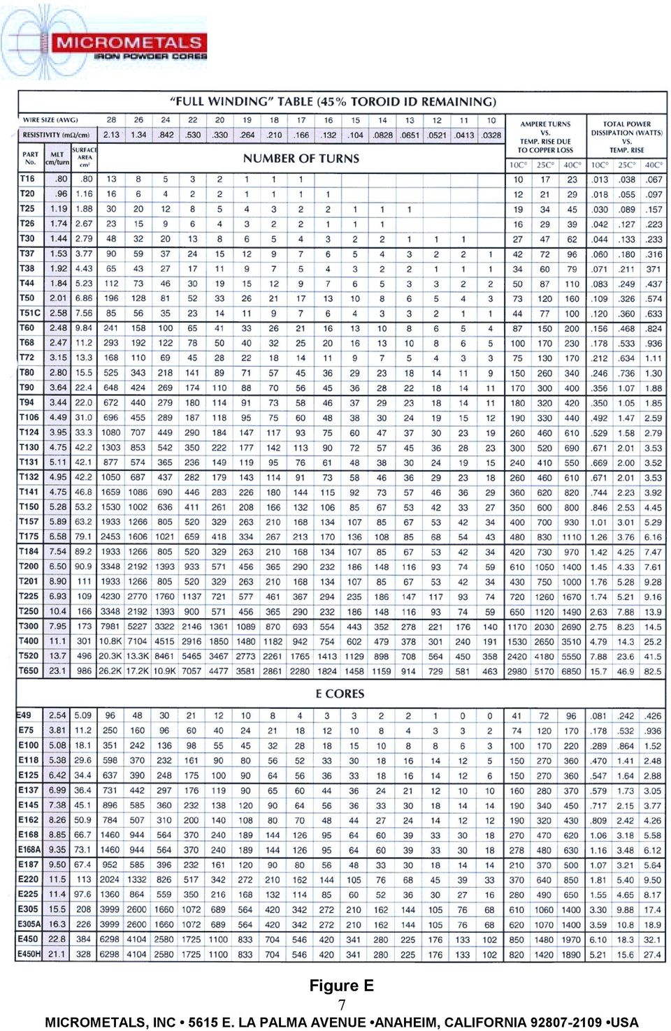
5 assuming 250 circular mills per amp for a single layer toroidal winding, #26 AWG would be selected for a 1 amp application resulting in a temperature rise of about 10 C. Using the same "rule of thumb" for a 25 amp application, #12 AWG would be selected, this time resulting in a 40 C temperature rise. For single layer windings on toroidal cores, current handling capability versus temperature rise is independent of core size. Making use of this, a single layer winding table, has been developed as shown in Figure D on the following page. This table lists current ratings, in amperes, for various wire sizes for temperature rises of 10, 25, and 40 C. For example, the table shows that in a 3amp single-layer winding with a maximum allowable temperature rise due to copper loss of 10 C that #19 wire should be used. If the allowable temperature rise is increased to 25 C, the same wire can handle 5.26 amps; while a 40 C rise will allow operation at 6.81 amps. For "Full Windings" (45% of the toroids inside diameter remaining) a similar table has been developed as shown in Figure E on page 7. When parts are wound to a constant fill-factor, it is possible to establish ampere-turns ratings as a function of temperature rise for the different core sizes. This table lists the maximum allowable ampere-turns for 10, 25, and 40 C temperature rise due to copper loss for both toroidal and E-cores. Both of these tables also list the DC resistivity in milliohms per centimeter for the different wire sizes as well as the mean length per turn (MLT) for the various core sizes. This information makes it very convenient to calculate the DC resistance (in milliohms) for a given winding by simply multiplying the wire resistivity times the MLT times the number of turns. These tables also list the "Surface Area" in cm² for the different core sizes. This number reflects the effective surface area of a typical wound component. This information is useful in determining temperature rise as a function of power dissipation. The following formula has been used to generate this information in both tables: Total Power Dissipation (milliwatts) Rise(C ) = Surface Area (cm 2 ) While there do exist many DC output choke applications which do not have enough AC content to generate any appreciable core loss, most of the higher voltage, higher frequency DC chokes and power factor correction inductors do need to take core loss into account. Additionally, designs for 60 Hz differential-mode inductors and AC resonant inductors are quite significantly affected by core loss

6 Figure D 6

7 Figure E 7
8 Core Losses: Core losses are a result of an alternating magnetic field in a core material. The loss generated for a given material is a function of operating frequency and total flux swing ( B). The core losses are due to Hysteresis, eddy current and residual losses in the core material. Iron powder has higher core loss than some other more expensive core materials, and it will sometimes become a limiting factor in applications with relatively high ripple current at very high frequency. Consequently, it is important to have a good understanding of the proper evaluation of core loss. A core loss curve for the -26 Material is shown below in Figure F. (Curve-fit formulas are also provided to describe these characteristics.) The core loss characteristics are presented in milliwatts per cubic centimeter as a function of peak AC flux density. This information results from sinewave core loss measurements make on a Clarke-Hesse Wattmeter. -26 Material µ=75 Relative Cost = 1.2 Figure F 8

9 A formula commonly used to calculate peak AC flux density is: Bpk = 8 E rms A N f Where: Bpk = Peak AC flux density (gauss) E rms = RMS sinewave voltage (volts) A = Effective cross-sectional area (cm²) N = Number of turns f = Frequency (hertz) This formula is useful in determining the value of peak AC flux density to be used with the core loss curves for sinewave applications such as 60 Hz differential-mode line filter inductors, resonant inductors, and for the fundamental line frequency signal in power factor correction chokes. Under this condition, the core experiences a total peak to peak AC flux density swing ( B) that is twice the value of peak AC flux density (Bpk) calculated with the preceding formula as illustrated: Biasing a magnetic material with DC current will shift the minor alternating BH loop but will not have a noticeable effect on the core loss. It is only the alternating flux density ( B) that generates core loss. This condition is illustrated: 9

10 The following diagram describes a typical squarewave voltage across an inductor in a switching power supply: Since the volt-seconds (Et) during the "on" and "off" portion of a period must be equal in the steady-state, the peak to peak flux density for a squarewave (which is not necessarily symmetric) is described by the following formula in cgs units: B = Epk t 10 A N 8 Where:!B = Peak to Peak flux density (gauss) Epk = Peak voltage across coil during "t" t = Time of applied voltage (seconds) A = Cross-sectional area (cm²) N = Number of turns In unipolar applications such as flybacks, the above formulas, which describe the total peak to peak flux density, need to be used to verify operation within the maximum flux density limit of the core material in order to avoid magnetic saturation. However, since it is industry practice to show core loss as a function of peak AC flux density with symmetrical operation about zero, the core loss curves provided assume that the peak AC flux density is half the peak to peak value (Bpk =!B/2). Therefore, core loss is determined from the graphs by using one-half of the peak to peak flux density at the frequency of the total period where f = 1/tp. The following formulas should be used to calculate the value of peak AC flux density used with the core loss graphs for most DC choke applications: 8 Epk t 10 Bpk = 2 A N Where: Bpk = Peak AC flux density (!B/2) (Gauss) Epk = Peak voltage across coil during "t" (volt) t = Time of applied voltage (seconds) A = Cross-sectional area (cm²) N = Number of turns 10

11 In coupled output inductors, this same formula can be used by considering only one of the outputs; since the volt-seconds per turn are the same for all outputs and they are all working in unison. Inductors in power factor correction boost topologies do not have the simple steady-state waveform presented previously. Rather, the high frequency signal is such that both the peak voltage across the inductor (E) and the "on" time (t) are constantly changing though out the period of the fundamental line frequency (50 or 60 Hz). The core loss in this case will be the time-averaged core loss of the individual pulses for the period of the line frequency. The flux density generated is dependent on the volt-seconds per pulse, while the core loss is dependent on approximately the square of the flux density. In order to estimate the high frequency core loss in this type of application, it is recommended that the rms value of voltseconds during the period of the line frequency be approximated and used in the preceding formula. This will provide the value of peak AC flux density to be used with the core loss curves. The frequency is the repetition rate of the high frequency signal. In addition to the high frequency core loss in a power factor correction inductor, the fundamental line frequency will also generate core loss. This loss should also be included when determining the total loss. Since a cores ability to dissipate heat (surface area) varies squared with its size, but a cores generation of heat due to its magnetic losses varies cubed (volume) with its size, physically small cores can dissipate more power per unit volume than physically large cores. Below is a table which illustrates this through several examples: T30 is a toroidal core with an outside diameter of 0.30 inches, while T400 is a 4.00 inch outside diameter toroid. Power Dissipation in mw/cm³ as a function of temp. rise Core Size 10 C 25 C 40 C T T T T T T T DC Output Inductor: Since DC flux does not generate core loss, the primary concern in most low voltage DC output inductors operating below 50 khz becomes saturation and copper loss. DC energy storage curves have been generated for a 1% ripple condition. The 1% ripple condition implies that this set of curves is not taking into account any effects due to AC or ripple content. These curves are based simply on DC saturation and DC winding losses. For this set of conditions, two sets of energy storage curves have been produced. These are shown on the following page, Figure G. 11
. The core loss in this case will be the time-averaged core loss of the individual pulses for the period of the line frequency.")
12 Figure G 12

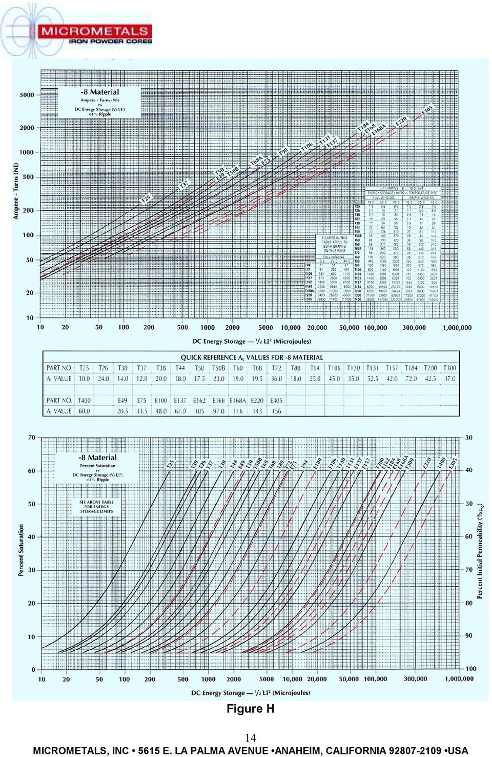
13 The set of curves at the top shows energy storage as a function of ampere-turns for the -26 Material. The set of curves at the bottom show energy storage as a function of percent saturation (percent saturation = 100% - percent initial permeability). Percent saturation is a sometimes misunderstood description. What is meant by percent saturation is simply that if a core is operating at 90% of its initial permeability (90% of its lowlevel inductance value) then it is 10% saturated. Similarly, a core that is 30% saturated is operating at 70% of its initial permeability. The use of both of these curves allows easy determination of required turns for a given amount of energy storage and also provides information on the amount of "swing" the inductor will have. "Swing" is a term sometimes used to describe an output chokes change in inductance with changes in operating current. A 30 µh, 10 amp example can be used to illustrate the use of these curves. 30 µh, 10 amps is 1500 µj. The table contained in the top graph shows that the T106 size core can store the required 1500 µj with a simple winding for a 25 C temperature rise. The curve for this core indicates that this will require about 250 ampere-turns. Since this is a 10 amp application, 25 turns will be required. Further, by referring to the graph at the bottom of the page, it can be seen that 1500 µj will result in the core operating at 49% saturation. This means that the core will produce 59 µh with a small amount of current flowing. By referring to the single layerwinding table it can be determined that #16 wire will fit in a single layer. Looking as this same 30 µh 10 amp application on the -8 Material DC energy storage curves, shown in Figure H on page 14, shows that this material can also store the required energy in the T106 size. In this case it will require 270 ampere-turns, or 27 turns of #16 wire. Referring to the curves at the bottom of the page shows that with this material, the T106 size core will be operating at only 10% saturation. This means that at low current the inductor will produce 33 µh, which means that this material will "swing" very little. 13
 then it is 10% saturated.")
14 Figure H 14
15 Coupled output chokes are also commonly used in multiple output supplies primarily to help improve cross regulation. The energy storage curves can still be used to assist in the design. A typical situation is illustrated below: Proper operation of a coupled inductor requires that the turns-ratios of the transformer and coupled inductor be the same: N1 N 2 N 3 = = N A N B N C If the ampere-turns in N 2 and N 3 are treated as if it were all in N 1, it is possible to view the requirement as if it were a single winding choke. N 2 I X = I1 + I 2 + N1 I 3 N N 3 1 Since the ampere-turns have been treated as if they are in N 1, the required inductance for output 1 is then used with the total effective current I x to calculate the total energy storage required: 1 2 LI X 2 This value of energy storage is then used to select the required E-core or toroidal core size. The energy storage curves will provide the total ampere-turns needed (N 1 I x ) which allows easy determination for the value of N 1. The required turns-ratios determine the values of N 2 and N 3. The previous examples have assumed that the AC content of the chokes has been an insignificant consideration. While this greatly simplifies the design considerations, as operating frequencies continued to increase, the core loss consideration becomes increasingly important. 15

16 In response to the need for better core materials for high frequency output chokes, two new iron powder materials were introduced a few years ago: -18 and -52 Materials. Figure I, below, shows a brief core loss comparison of these and the other materials. Figure I The -52 Material is produced to the same permeability as the -26 Material, has about 40% less core loss at frequencies above 100 khz and is available at a similar cost. The -18 Material has higher permeability than the -8 Material, is less expensive and has similar low core loss characteristics. In DC output chokes with elevated AC content, not only does the presence of the AC need to be considered for core loss reasons, but it will also have an effect on the inductance. A graph showing the materials response to elevated AC flux density is shown below in Figure J. Figure J 16

17 Figure K When both elevated AC and DC are present a combined effect results. A graph illustrating this effect for the -26 Material is shown above in Figure K. This graph shows that while the increasing level of DC bias causes the core materials permeability to decrease, that as the level of AC increases it causes the permeability to climb. This property means that output chokes with elevated AC levels will require fewer turns than would be predicted by only considering the DC effects. Consider the 30 µh, 10 amp inductor described earlier. This time consider this inductor with 12.7 volts across it at 100 khz (50% duty cycle). This inductor will be evaluated using each of the core materials on the T106 size core. In each case, the number of turns has been determined by using the energy storage curves. This is always a good first pass approach. Since these curves do not take into account the presence of the elevated AC signal, the results with AC are somewhat different. The results shown include the effect of the elevated AC flux density. The inductance with 12.7 volts at 100 khz and 0 ADC is listed as well as the inductance with the 10 amps DC. This allows comparison of the relative swing of each material. The winding loss (I²R) and core loss resulting from the listed Bpk are also shown: 17
.")
18 Turns L L Bpk I²R Core Total Mat'l #16 0 ADC 10 ADC (G) Loss Loss Loss It can be seen that in all cases the inductance with DC has increased above the required 30 µh. In most circuits this is desirable. The -18 and -8 Materials provide the lowest overall loss. These are also the most expensive core materials (relative cost 2.8 and 4.0). The -52 Material provides the next best performance and this material is considerably less expensive (relative cost 1.4). The higher permeability material like the -26 and -52 Materials have the greatest change (about 2 times) in inductance from 0 ADC to full rated current. This swing will keep the inductor in continuous conduction to a lower current than if it did not swing. Applications requiring continuous operation down to very low loads can require a low current inductance that is 10 to 20 times that of the full current inductance. This can be accomplished with Composite Toroids, which are made by combining a high permeability ferrite toroid with an iron powder toroid. The ferrite provides the high inductance needed under low current conditions and the iron powder provides the energy storage required under the high current conditions. The DC saturation characteristics are shown below: Figure L 18
. The -52 Material provides the next best performance and this material is considerably less expensive (relative cost 1.4).")
19 Power factor correction inductors contain both a bias current and a lower level high frequency signal. These inductors in typical boost topologies see both a continually changing bias current (50 or 60 Hz) as well as a continually changing high frequency ripple condition. The combination of these two effects makes the evaluation of these inductors more complicated than typical DC chokes. The core loss considerations are discussed on page 11. It is generally recommended that the bias current be treated as DC current. This will provide the most conservative design. 60 Hz Line Filter Inductors: A typical inductor requirement in a switch-mode power supply is in the 60 Hz line filter. The high frequency to be filtered in this application falls into two categories: common-mode and differential-mode noise. Briefly, common-mode noise is noise that is common to both the hot and neutral lines in relation to earth ground. Differential-mode noise is the noise between the hot and neutral lines. The common-mode filtering requires capacitors to earth ground. Safety regulations limit these capacitors to a relatively low value. This mandated low value of capacitance for commonmode filtering makes a high value of inductance essential to effective filtering. Common-mode inductors typically require a minimum inductance of 1000 µh and are most often wound in a balun configuration on a high permeability core; typically a 5000 or higher permeability ferrite. The balun winding allows the 60 Hz flux generated by each line to cancel in the core, thus avoiding saturation. Lower permeability materials like iron powder can be used in this application, but the increased core size to accommodate the number of turns needed to achieve the required inductance makes this alternative less attractive. The differential-mode inductors, however, must be able to support significant 60 Hz flux without saturating and at the same time respond to the high frequency noise. Iron powder is well suited for this requirement. A graph of percent permeability versus peak AC flux density was shown previously in Figure J on page 16. This graph shows that the saturation flux density of the materials is greater than 10,000 gauss (it ultimately reaches about 14,000 gauss). It also shows that the higher permeability materials like the -26 Material increase in permeability quite significantly in the presence of elevated AC flux density. Referring back to the -26 Material core loss information in Figure F on page 8, it can be seen that at a frequency of 60 Hz this material can operate at very high AC flux density without generating excessive core loss. It can also be seen that the core loss characteristics of this material are fairly high at the higher frequencies. These losses produce a coil with low Q at high frequency. This characteristic is of additional benefit in helping to suppress the unwanted signals. 60 Hz energy storage curves are provided which are based on the core materials response to AC flux density as described in Figure J. While the 60 Hz signal experiences these effects, it is not clear if the low-level noise signal experiences the same increased permeability. The most conservative design approach is to consider the 60 Hz current as DC current. Resonant AC Inductors: Another use for energy storage inductors is in AC resonant applications. This type of inductor is being driven by all high frequency AC current. In order to keep the core loss to an acceptable level, it is necessary to minimize the operating flux density. This is accomplished by utilizing lower permeability materials that will require more 19

20 turns so that the same amount of voltage drop (same current flowing) will result in a lower operating AC flux density. One method of lowering effective permeability and thus lowering the operating flux density is to introduce a localized air gap. At frequencies above 100 khz, the additional "gap loss" generated by the high frequency fringing can cause severe localized heating problems. In many instances, the "gap loss" alone can be greater than the calculated core loss. Iron powder has been produced for many years for use in high power communication circuits operating from 500 khz to several MHz. One of the materials which is gaining popularity in resonant power supply applications is the -2 Material. This material has a permeability of 10 which helps keep the operating flux density low without creating localized gap-loss problems. At these high frequencies, the use on litz wire is essential in minimizing the AC winding losses. Figure M, at the top of the following page, shows the core loss characteristics of the -2 Material up to a frequency of 2.5 MHz. This information has been used to produce Figure N at the bottom of the same page. This graph illustrates AC RMS current as a function of inductance for the -2 Material when operated at a frequency of 1 MHz. This information is based on limiting the temperature rise resulting from core loss to 25 C. While the -2 Material is the material of choice for resonant applications above 20 khz, the -30 Material should be considered for lower frequency AC inductors in very high power UPS applications operating in the 1 khz to 5 khz frequency range. This material provides a good balance of permeability, core loss, saturation characteristics, and core cost. 20

21 Figure M Figure N 21
22 Summary: An overview of iron powder as a core material has been presented. It has been shown that its magnetic characteristics make it well suited for a number of different inductor applications in switch-mode power supplies. It is one of the least inexpensive core materials available and is being widely used in today's commercial switching power supply industry. 22
ABSTRACT 1. INTRODUCTION
 Inductor Cores Material and Shape Choices by Mark A. Swihart, Manager of Applications Engineering Magnetics, Division of Spang & Co. Pittsburgh, Pennsylvania USA ABSTRACT A carefully considered power inductor
Selecting IHLP Composite Inductors for Non-Isolated Converters Utilizing Vishay s Application Sheet
 VISHAY DALE www.vishay.com Magnetics Selecting IHLP Composite Inductors for Non-Isolated Converters INTRODUCTION This application note will provide information to assist in the specification of IHLP composite
Inductor and Magnetic Product Terminology
 INTRODUCTION IFC LPT ILB IHSM IM IMC LPE TJ LPC IRF IHB The scope of this application note is to define the terminology associated with inductors and their applications. Some of these terms are listed
Toroids. Toroids. Design Considerations
 Ferrite toroids provide an often convenient and very effective shape for many wide band, pulse and power transformers and inductors. The continuous magnetic path yields the highest effective permeability
Chapter 14: Inductor design
 Chapter 14 Inductor Design 14.1 Filter inductor design constraints 14.2 A step-by-step design procedure 14.3 Multiple-winding magnetics design using the K g method 14.4 Examples 14.5 Summary of key points
INDUCTOR DESIGN IN SWITCHING REGULATORS
 Division of Spang & Company Technical Bulletin BULLETIN SR-1A INDUCTOR DESIGN IN SWITCHING REGULATORS Better efficiency, reduced size, and lower costs have combined to make the switching regulator a viable
Application Note. So You Need to Measure Some Inductors?
 So You Need to Measure Some nductors? Take a look at the 1910 nductance Analyzer. Although specifically designed for production testing of inductors and coils, in addition to measuring inductance (L),
Chapter 15: Transformer design
 Chapter 15 Transformer Design Some more advanced design issues, not considered in previous chapter: : n Inclusion of core loss + + Selection of operating flux i 1 density to optimize total loss v 1 v Multiple
Renco Electronics, Inc.
 Abstract As high tech electronic products and their power supplies continue to shrink in size the peak current handling capability of power inductors should be looked at closely by the design engineer.
Application Notes. Magnetics. Determining L min for Buck/Boost Converters
 Application Notes Magnetics etermining min for Buck/Boost onverters Fundamental oncepts 172 alculating Minimum nductance Buck Type onverters 174 Boost Type onverters 177 Buck-Boost onverters 180-171 APPATON
Edmund Li. Where is defined as the mutual inductance between and and has the SI units of Henries (H).
.") INDUCTANCE MUTUAL INDUCTANCE If we consider two neighbouring closed loops and with bounding surfaces respectively then a current through will create a magnetic field which will link with as the flux passes
INDUCTANCE MUTUAL INDUCTANCE If we consider two neighbouring closed loops and with bounding surfaces respectively then a current through will create a magnetic field which will link with as the flux passes
Improved PFC Boost Choke using a Quasi-Planar Winding Configuration Dave Shonts Schott Corporation 1000 Parkers Lake Road Wayzata, MN 55391
 Improved PFC Boost Choke using a Quasi-Planar Winding Configuration Dave Shonts Schott Corporation 1000 Parkers Lake Road Wayzata, MN 55391 Abstract- A novel approach to boost inductor design using a quasi-planar
Line Reactors and AC Drives
 Line Reactors and AC Drives Rockwell Automation Mequon Wisconsin Quite often, line and load reactors are installed on AC drives without a solid understanding of why or what the positive and negative consequences
Homework #11 203-1-1721 Physics 2 for Students of Mechanical Engineering
 Homework #11 203-1-1721 Physics 2 for Students of Mechanical Engineering 2. A circular coil has a 10.3 cm radius and consists of 34 closely wound turns of wire. An externally produced magnetic field of
Chapter 16. Current Transformer Design. Copyright 2004 by Marcel Dekker, Inc. All Rights Reserved.
 Chapter 16 Current Transformer Design Table of Contents 1. Introduction 2. Analysis of the Input Current Component 3. Unique to a Current Transformer 4. Current Transformer Circuit Applications 5. Current
An equivalent circuit of a loop antenna.
 3.2.1. Circuit Modeling: Loop Impedance A loop antenna can be represented by a lumped circuit when its dimension is small with respect to a wavelength. In this representation, the circuit parameters (generally
LECTURE 31 Inductor Types and Associated Magnetic Cores
 LECTURE 31 Inductor Types and Associated Magnetic Cores 1 A. Magnetic Core Choices to Wind Cu Wire Around 1. Available Magnetic Cores a. Commercial Core Geometry s b. Available Core Materials(B SAT,µ vs.
Planar versus conventional transformer
 Planar versus conventional transformer Majid Dadafshar, Principal Engineer Gerard Healy, Field Application Engineer Pulse, a Technitrol Company Power Division Usually the first step on any power supply
Power Supplies. 1.0 Power Supply Basics. www.learnabout-electronics.org. Module
 Module 1 www.learnabout-electronics.org Power Supplies 1.0 Power Supply Basics What you ll learn in Module 1 Section 1.0 Power Supply Basics. Basic functions of a power supply. Safety aspects of working
ALLOY POWDER CORE SERIES INTRODUCTION
 ALLOY POWDER CORE SERIES INTRODUCTION 1 DMEGC alloy powder cores are made from insulated pretreatment alloy powders which have low losses at elevated temperature and have relatively stable inductance over
A Simple Current-Sense Technique Eliminating a Sense Resistor
 INFINITY Application Note AN-7 A Simple Current-Sense Technique Eliminating a Sense Resistor Copyright 998 A SIMPE CURRENT-SENSE TECHNIQUE EIMINATING A SENSE RESISTOR INTRODUCTION A sense resistor R S,
DIRECT CURRENT GENERATORS
 DIRECT CURRENT GENERATORS Revision 12:50 14 Nov 05 INTRODUCTION A generator is a machine that converts mechanical energy into electrical energy by using the principle of magnetic induction. This principle
Chapter 10. AC Inductor Design. Copyright 2004 by Marcel Dekker, Inc. All Rights Reserved.
 Chapter 10 AC Inductor Design Table of Contents 1. Introduction 2. Requirements 3. Relationship of, A p, to the Inductor Volt-Amp Capability 4. Relationship of, K g, to the Inductor Volt-Amp Capability
EMI and t Layout Fundamentals for Switched-Mode Circuits
 v sg (t) (t) DT s V pp = n - 1 2 V pp V g n V T s t EE core insulation primary return secondary return Supplementary notes on EMI and t Layout Fundamentals for Switched-Mode Circuits secondary primary
HPS Universal. Single and Three Phase Potted. Buck-Boost Transformers. Buck-Boost Applications & Standard Specification... 80
 Buck-Boost Transformers Single and Three Phase Potted Buck-Boost Transformers Buck-Boost Applications & Standard Specification... 80 Selecting Buck-Boost Transformers... 81 Single Phase Selection Tables...
April 1. Physics 272. Spring 2014 http://www.phys.hawaii.edu/~philipvd/pvd_14_spring_272_uhm.html. Prof. Philip von Doetinchem philipvd@hawaii.
 Physics 272 April 1 Spring 2014 http://www.phys.hawaii.edu/~philipvd/pvd_14_spring_272_uhm.html Prof. Philip von Doetinchem [email protected] Phys272 - Spring 14 - von Doetinchem - 164 Summary Gauss's
Which is the best PFC stage for a 1kW application?
 Which is the best PFC stage for a 1kW application? Comparison of different PFC stage topologies under an identical design philosophy Ulf Schwalbe/ Marko Scherf ISLE Steuerungstechnik und Leistungselektronik
Drive circuit basics + V. τ e. Industrial Circuits Application Note. Winding resistance and inductance
 ndustrial Circuits Application Note Drive circuit basics For a given size of a stepper motor, a limited space is available for the windings. n the process of optimizing a stepper motor drive system, an
Solar Inverters. Ferrites in Renewable Energies: Solar Inverters. customer requirements. Support and flexibility to design custom product to fulfill
 Support and flexibility to design custom product to fulfill customer requirements Optimum ferrite material selection for magnetic applications in the design for cost saving, and performance improvement
Selecting the Optimal Inductor for Power Converter Applications
 Selecting the Optimal Inductor for Power Converter Applications BACKGROUND Today s electronic devices have become increasingly power hungry and are operating at higher switching frequencies, starving for
EE301 Lesson 14 Reading: 10.1-10.4, 10.11-10.12, 11.1-11.4 and 11.11-11.13
 CAPACITORS AND INDUCTORS Learning Objectives EE301 Lesson 14 a. Define capacitance and state its symbol and unit of measurement. b. Predict the capacitance of a parallel plate capacitor. c. Analyze how
Designing with Magnetic Cores at High Temperatures
 Technical Bulletin Designing with Magnetic Cores at High Temperatures All cores are not the same. Designers need to know the differences in order to make the best choices. Thermal considerations are a
Coupling Magnetic Signals to a SQUID Amplifier
 SQUID Application Note 105-0 Coupling Magnetic Signals to a SQUID Amplifier Matching the effective inductances of the Pickup Coil and the Input Coil to detect and couple magnetic flux maximizes the sensitivity
Power supplies. EE328 Power Electronics Assoc. Prof. Dr. Mutlu BOZTEPE Ege University, Dept. of E&E
 Power supplies EE328 Power Electronics Assoc. Prof. Dr. Mutlu BOZTEPE Ege University, Dept. of E&E EE328 POWER ELECTRONICS Outline of lecture Introduction to power supplies Modelling a power transformer
TN0023 Technical note
 Technical note Discontinuous flyback transformer description and design parameters Introduction The following is a general description and basic design procedure for a discontinuous flyback transformer.
Module 11: Conducted Emissions
 Module 11: Conducted Emissions 11.1 Overview The term conducted emissions refers to the mechanism that enables electromagnetic energy to be created in an electronic device and coupled to its AC power cord.
Understanding SMD Power Inductors. Application Note. July 2011
 Understanding SMD Power Inductors July 2011 Application Note Power inductors play an important role in voltage conversion applications by yielding lower core losses. They are also used to store energy,
SELECTION GUIDE. Nominal Input
 www.murata-ps.com NKE Series FEATURES RoHS Compliant Sub-Miniature SIP & DIP Styles 3kVDC Isolation UL Recognised Wide Temperature performance at full 1 Watt load, 40 C to 85 C Increased Power Density
Digital Energy ITI. Instrument Transformer Basic Technical Information and Application
 g Digital Energy ITI Instrument Transformer Basic Technical Information and Application Table of Contents DEFINITIONS AND FUNCTIONS CONSTRUCTION FEATURES MAGNETIC CIRCUITS RATING AND RATIO CURRENT TRANSFORMER
Magnetics in Switched-Mode Power Supplies
 Magnetics in Switched-Mode Power Supplies Agenda Block Diagram of a Typical AC-DC Power Supply Key Magnetic Elements in a Power Supply Review of Magnetic Concepts Magnetic Materials Inductors and Transformers
Charger Output AC Ripple Voltage and the affect on VRLA batteries
 TECHNICAL BULLETIN 41-2131 Charger Output AC Ripple Voltage and the affect on VRLA batteries Please Note: The information in this technical bulletin was developed for C&D Dynasty 12 Volt VRLA products.
Application Note AN:005. FPA Printed Circuit Board Layout Guidelines. Introduction Contents. The Importance of Board Layout
 FPA Printed Circuit Board Layout Guidelines By Paul Yeaman Principal Product Line Engineer V I Chip Strategic Accounts Introduction Contents Page Introduction 1 The Importance of 1 Board Layout Low DC
CHAPTER 4 DESIGN OF INTEGRAL SLOT AND FRACTIONAL SLOT BRUSHLESS DC MOTOR
 47 CHAPTER 4 DESIGN OF INTEGRAL SLOT AND FRACTIONAL SLOT BRUSHLESS DC MOTOR 4.1 INTRODUCTION This chapter deals with the design of 24 slots 8 poles, 48 slots 16 poles and 60 slots 16 poles brushless dc
Application Note, Rev.1.0, September 2008 TLE8366. Application Information. Automotive Power
 Application Note, Rev.1.0, September 2008 TLE8366 Automotive Power Table of Contents 1 Abstract...3 2 Introduction...3 3 Dimensioning the Output and Input Filter...4 3.1 Theory...4 3.2 Output Filter Capacitor(s)
High Voltage Power Supplies for Analytical Instrumentation
 ABSTRACT High Voltage Power Supplies for Analytical Instrumentation by Cliff Scapellati Power supply requirements for Analytical Instrumentation are as varied as the applications themselves. Power supply
2. A conductor of length 2m moves at 4m/s at 30 to a uniform magnetic field of 0.1T. Which one of the following gives the e.m.f. generated?
 Extra Questions - 2 1. A straight length of wire moves through a uniform magnetic field. The e.m.f. produced across the ends of the wire will be maximum if it moves: a) along the lines of magnetic flux
Chapter 11. Inductors ISU EE. C.Y. Lee
 Chapter 11 Inductors Objectives Describe the basic structure and characteristics of an inductor Discuss various types of inductors Analyze series inductors Analyze parallel inductors Analyze inductive
Circuits with inductors and alternating currents. Chapter 20 #45, 46, 47, 49
 Circuits with inductors and alternating currents Chapter 20 #45, 46, 47, 49 RL circuits Ch. 20 (last section) Symbol for inductor looks like a spring. An inductor is a circuit element that has a large
Lecture 24. Inductance and Switching Power Supplies (how your solar charger voltage converter works)
") Lecture 24 Inductance and Switching Power Supplies (how your solar charger voltage converter works) Copyright 2014 by Mark Horowitz 1 Roadmap: How Does This Work? 2 Processor Board 3 More Detailed Roadmap
Lecture 24 Inductance and Switching Power Supplies (how your solar charger voltage converter works) Copyright 2014 by Mark Horowitz 1 Roadmap: How Does This Work? 2 Processor Board 3 More Detailed Roadmap
Topic 4. Designing Planar Magnetics
 Topic 4 Designing Planar Magnetics Designing Planar Magnetics Lloyd Dixon, Texas Instruments ABSTRACT Planar magnetic devices offer several advantages over their conventional counterparts. This paper
Solar Energy Conversion using MIAC. by Tharowat Mohamed Ali, May 2011
 Solar Energy Conversion using MIAC by Tharowat Mohamed Ali, May 2011 Abstract This work introduces an approach to the design of a boost converter for a photovoltaic (PV) system using the MIAC. The converter
ES250: Electrical Science. HW7: Energy Storage Elements
 ES250: Electrical Science HW7: Energy Storage Elements Introduction This chapter introduces two more circuit elements, the capacitor and the inductor whose elements laws involve integration or differentiation;
Section 4 Power Transformer Design
 Section 4 Power Transformer Design Power Transformer Design This Section covers the design of power transformers used in buck-derived topologies: forward converter, bridge, half-bridge, and full-wave centertap.
Theory of Heating by Induction
 CHAPTER 2 Theory of Heating by Induction INDUCTION HEATING was first noted when it was found that heat was produced in transformer and motor windings, as mentioned in the Chapter Heat Treating of Metal
Understanding Power Impedance Supply for Optimum Decoupling
 Introduction Noise in power supplies is not only caused by the power supply itself, but also the load s interaction with the power supply (i.e. dynamic loads, switching, etc.). To lower load induced noise,
Custom Products. Magnetic Components. Vishay Dale. www.vishay.com
 Magnetic Components SWITCH MODE MAGNETICS AIR CORE INDUCTORS INDUCTIVE PRODUCTS CUSTOM DESIGN AND PRODUCTION has extensive facilities for custom design and production of custom magnetics. Design applications
Common Mode Inductors for EMI Filters Require Careful Attention to Core Material Selection
 POWER Common Mode Inductors for EMI Filters Require Careful Attention to Core Material Selection Robert West, Magnetics, Division of Spang & Co., Butler, Pennsylvania The common mode inductor is an integral
UNDERSTANDING AND CONTROLLING COMMON-MODE EMISSIONS IN HIGH-POWER ELECTRONICS
 Page 1 UNDERSTANDING AND CONTROLLING COMMON-MODE EMISSIONS IN HIGH-POWER ELECTRONICS By Henry Ott Consultants Livingston, NJ 07039 (973) 992-1793 www.hottconsultants.com [email protected] Page 2 THE BASIC
Solution Derivations for Capa #11
 Solution Derivations for Capa #11 Caution: The symbol E is used interchangeably for energy and EMF. 1) DATA: V b = 5.0 V, = 155 Ω, L = 8.400 10 2 H. In the diagram above, what is the voltage across the
Inductors. AC Theory. Module 3
 Module 3 AC Theory What you ll learn in Module 3. Section 3.1 Electromagnetic Induction. Magnetic Fields around Conductors. The Solenoid. Section 3.2 Inductance & Back e.m.f. The Unit of Inductance. Factors
Common Mode Filter Inductor Analysis
 Document 2-1 Common Mode Filter Inductor Analysis Abstract Noise limits set by regulatory agencies make solutions to common mode EMI a necessary consideration in the manufacture and use of electronic equipment.
The performance improvement by ferrite loading means - increasing, - increasing of ratio, implicitly related to the input impedance.
 3.2.3. Ferrite Loading Magnetic ferrite loading can enhance a transmitting signal as high as 2 to 10 db for MHz [Devore and Bohley, 1977]. There is an optimum frequency range where ferrite loading is beneficial.
Evaluating AC Current Sensor Options for Power Delivery Systems
 Evaluating AC Current Sensor Options for Power Delivery Systems State-of-the-art isolated ac current sensors based on CMOS technology can increase efficiency, performance and reliability compared to legacy
Vrieswijk, T & Srinivasan,A Amerongen,NL, 25 januari 2012
 Theory Current Transformers Vrieswijk, T & Srinivasan,A Amerongen,NL, 25 januari 2012 Theory Current Transformers 25 januari 2012 Topics - Theory of current transformers (CTs) - Equivalent Circuit for
Current and Temperature Ratings
 Document 361-1 Current and Temperature Ratings Introduction This application note describes: How to interpret Coilcraft inductor current and temperature ratings Our current ratings measurement method and
The Flyback Converter
 The Flyback Converter Lecture notes ECEN4517! Derivation of the flyback converter: a transformer-isolated version of the buck-boost converter! Typical waveforms, and derivation of M(D) = V/! Flyback transformer
Modeling and Analysis of DC Link Bus Capacitor and Inductor Heating Effect on AC Drives (Part I)
") 00-00-//$0.00 (c) IEEE IEEE Industry Application Society Annual Meeting New Orleans, Louisiana, October -, Modeling and Analysis of DC Link Bus Capacitor and Inductor Heating Effect on AC Drives (Part
00-00-//$0.00 (c) IEEE IEEE Industry Application Society Annual Meeting New Orleans, Louisiana, October -, Modeling and Analysis of DC Link Bus Capacitor and Inductor Heating Effect on AC Drives (Part
Objectives. Electric Current
 Objectives Define electrical current as a rate. Describe what is measured by ammeters and voltmeters. Explain how to connect an ammeter and a voltmeter in an electrical circuit. Explain why electrons travel
Objectives. Capacitors 262 CHAPTER 5 ENERGY
 Objectives Describe a capacitor. Explain how a capacitor stores energy. Define capacitance. Calculate the electrical energy stored in a capacitor. Describe an inductor. Explain how an inductor stores energy.
Current Probes. User Manual
 Current Probes User Manual ETS-Lindgren L.P. reserves the right to make changes to any product described herein in order to improve function, design, or for any other reason. Nothing contained herein shall
BASIC ELECTRONICS AC CIRCUIT ANALYSIS. December 2011
 AM 5-202 BASIC ELECTRONICS AC CIRCUIT ANALYSIS December 2011 DISTRIBUTION RESTRICTION: Approved for Pubic Release. Distribution is unlimited. DEPARTMENT OF THE ARMY MILITARY AUXILIARY RADIO SYSTEM FORT
MAGNETICS: FERRITES, BEADS and BALUNS
 HF OPERATORS MAGNETICS: FERRITES, BEADS and BALUNS by John White VA7JW NSARC HF Operators 1 What s the Problem?! HF Dipoles and coaxial cables have a nasty compatibility problem! Dipoles are balanced structures!
104 Practice Exam 2-3/21/02
 104 Practice Exam 2-3/21/02 1. Two electrons are located in a region of space where the magnetic field is zero. Electron A is at rest; and electron B is moving westward with a constant velocity. A non-zero
GT Sensors Precision Gear Tooth and Encoder Sensors
 GT Sensors Precision Gear Tooth and Encoder Sensors NVE s GT Sensor products are based on a Low Hysteresis GMR sensor material and are designed for use in industrial speed applications where magnetic detection
45. The peak value of an alternating current in a 1500-W device is 5.4 A. What is the rms voltage across?
 PHYS Practice Problems hapters 8- hapter 8. 45. The peak value of an alternating current in a 5-W device is 5.4 A. What is the rms voltage across? The power and current can be used to find the peak voltage,
Lecture - 4 Diode Rectifier Circuits
 Basic Electronics (Module 1 Semiconductor Diodes) Dr. Chitralekha Mahanta Department of Electronics and Communication Engineering Indian Institute of Technology, Guwahati Lecture - 4 Diode Rectifier Circuits
Harmonics and Noise in Photovoltaic (PV) Inverter and the Mitigation Strategies
 Inverter and the Mitigation Strategies") Soonwook Hong, Ph. D. Michael Zuercher Martinson Harmonics and Noise in Photovoltaic (PV) Inverter and the Mitigation Strategies 1. Introduction PV inverters use semiconductor devices to transform the
Soonwook Hong, Ph. D. Michael Zuercher Martinson Harmonics and Noise in Photovoltaic (PV) Inverter and the Mitigation Strategies 1. Introduction PV inverters use semiconductor devices to transform the
EMI Conducted Interference
 Although the concepts stated are universal, this application note was written specifically for Interpoint products. Switching power converters are natural generators of input narrowband spectral noise
Principles of Adjustable Frequency Drives
 What is an Adjustable Frequency Drive? An adjustable frequency drive is a system for controlling the speed of an AC motor by controlling the frequency of the power supplied to the motor. A basic adjustable
POWER LINE FILTERS FOR SWITCHING POWER SUPPLIES
 POWER INE FITERS FOR SWITCHING POWER SUPPIES ing. Eugen COCA *, prof. dr. ing. Dimitrie AEXA ** * EECTRICA SA - SD SUCEAVA - ROMANIA ** U.T. Gh. Asachi IASI - ROMANIA * SEM0kV - PRAM str. Stefan cel Mare,
Design Considerations for an LLC Resonant Converter
 Design Considerations for an LLC Resonant Converter Hangseok Choi Power Conversion Team www.fairchildsemi.com 1. Introduction Growing demand for higher power density and low profile in power converter
Inductors & Inductance. Electronic Components
 Electronic Components Induction In 1824, Oersted discovered that current passing though a coil created a magnetic field capable of shifting a compass needle. Seven years later, Faraday and Henry discovered
DATA SHEET. TDA1510AQ 24 W BTL or 2 x 12 W stereo car radio power amplifier INTEGRATED CIRCUITS
 INTEGRATED CIRCUITS DATA SHEET 24 W BTL or 2 x 12 W stereo car radio File under Integrated Circuits, IC01 January 1992 GENERAL DESCRIPTION The is a class-b integrated output amplifier encapsulated in a
Fundamentals of Signature Analysis
 Fundamentals of Signature Analysis An In-depth Overview of Power-off Testing Using Analog Signature Analysis www.huntron.com 1 www.huntron.com 2 Table of Contents SECTION 1. INTRODUCTION... 7 PURPOSE...
DC GENERATOR THEORY. LIST the three conditions necessary to induce a voltage into a conductor.
 DC Generators DC generators are widely used to produce a DC voltage. The amount of voltage produced depends on a variety of factors. EO 1.5 LIST the three conditions necessary to induce a voltage into
CURRENT TRANSFORMERS FOR ELECTRONIC WATTHOUR METERS ADVANCED MATERIALS THE KEY TO PROGRESS
 CURRENT TRANSFORMERS FOR ELECTRONIC WATTHOUR METERS ADVANCED MATERIALS THE KEY TO PROGRESS CURRENT TRANSFORMERS FOR ELECTRONIC WATTHOUR METERS VACUUMSCHMELZE GmbH & Co. KG (VAC) is one of the worldwide
Current Ripple Factor of a Buck Converter
 Application Note Edwin Wang AN1 April 14 Current Ripple Factor of a Buck Converter Abstract Inductor and capacitor forms a low-pass filter in a buck converter. The corner frequency the C filter is always
POWER AND VOLTAGE RATING
 POWER AND VOLTAGE RATING SCOPE: The purpose of this document is to take the confusion out of power and voltage ratings in specifications and in product information publications. This will be accomplished
Magnetic Field Evaluation in Transformers and Inductors
 Magnetic Field Evaluation in Transformers and Inductors By Lloyd H. Dixon This topic reveals, by means of magnetic field plots, many of the problems that occur in magnetic device structures, utilizing
RC NETWORKS SALES GUIDE
 SALES GUIDE INTRODUCTION TO Recent developments in electronic equipment have shown the following trends: Increasing demands for numerical control machines, robotics and technically advanced appliances
Eðlisfræði 2, vor 2007
 [ Assignment View ] [ Print ] Eðlisfræði 2, vor 2007 30. Inductance Assignment is due at 2:00am on Wednesday, March 14, 2007 Credit for problems submitted late will decrease to 0% after the deadline has
7-41 POWER FACTOR CORRECTION
 POWER FTOR CORRECTION INTRODUCTION Modern electronic equipment can create noise that will cause problems with other equipment on the same supply system. To reduce system disturbances it is therefore essential
KNOWLEDGE BASE ARTICLE Zero Voltage Transmission (ZVT) Technology. Basics of the GPZ 7000 Technology: Zero Voltage Transmission (ZVT)
 Technology. Basics of the GPZ 7000 Technology: Zero Voltage Transmission (ZVT)") KNOWLEDGE BASE ARTICLE Zero Voltage Transmission (ZVT) Technology Basics of the GPZ 7000 Technology: Zero Voltage Transmission (ZVT) By Bruce Candy Basic Metal Detection Principles 1 2 3 4 Simplified representation
KNOWLEDGE BASE ARTICLE Zero Voltage Transmission (ZVT) Technology Basics of the GPZ 7000 Technology: Zero Voltage Transmission (ZVT) By Bruce Candy Basic Metal Detection Principles 1 2 3 4 Simplified representation
Creating a Usable Power Supply from a Solar Panel
 Creating a Usable Power Supply from a Solar Panel An exploration in DC- DC converters By Kathleen Ellis Advised by Dr. Derin Sherman Department of Physics, Cornell College November 21, 2012 Introduction
Since any real component also has loss due to the resistive component, the average power dissipated is 2 2R
 Quality factor, Q Reactive components such as capacitors and inductors are often described with a figure of merit called Q. While it can be defined in many ways, it s most fundamental description is: Q
Basics of Electricity
 Basics of Electricity Generator Theory PJM State & Member Training Dept. PJM 2014 8/6/2013 Objectives The student will be able to: Describe the process of electromagnetic induction Identify the major components
Quality Policy Statement... I.F.C. Introduction... 2 Magnetic Properties of Fair-Rite Materials... 4 Fair-Rite Materials... 6
 4th Edition Table of Contents Quality Policy Statement... I.F.C. Introduction... 2 Magnetic Properties of Fair-Rite Materials... 4 Fair-Rite Materials... 6 Board Components EMI Suppression Beads... 24
d di Flux (B) Current (H)
 Current (H)") Comparison of Inductance Calculation Techniques Tony Morcos Magnequench Technology Center Research Triangle Park, North Carolina 1 VCM Baseline: Geometry Axially-magnetized MQ3-F 42 NdFeB disk Br = 131kG
Comparison of Inductance Calculation Techniques Tony Morcos Magnequench Technology Center Research Triangle Park, North Carolina 1 VCM Baseline: Geometry Axially-magnetized MQ3-F 42 NdFeB disk Br = 131kG
GenTech Practice Questions
 GenTech Practice Questions Basic Electronics Test: This test will assess your knowledge of and ability to apply the principles of Basic Electronics. This test is comprised of 90 questions in the following
Impedance Matching and Matching Networks. Valentin Todorow, December, 2009
 Impedance Matching and Matching Networks Valentin Todorow, December, 2009 RF for Plasma Processing - Definition of RF What is RF? The IEEE Standard Dictionary of Electrical and Electronics Terms defines