Motors and Generators
|
|
|
- Stanley Perry
- 9 years ago
- Views:
Transcription
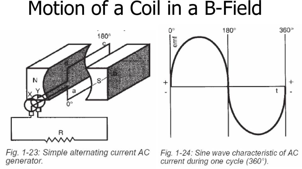
1 Motors and Generators Electro-mechanical devices: convert electrical energy to mechanical motion/work and vice versa Operate on the coupling between currentcarrying conductors and magnetic fields Governed by a set of fundamental principles

2 Magnetism Magnets are composed of north and south pole pairs. B-field lines go from the north to the south poles. N S

3 Principle #1 Current in a conductor results in a magnetic field around the conductor. Use the righthand rule to determine the field direction. i B

4 Principle #2 Moving a conductor in a magnetic field induces a voltage across the conductor according to B S N

5 Motion of a Coil in a B-Field

6 Commutation

7 Motion of a Coil in a B-Field
8 Motion of a Coil (cont.)

9 Commutation

10 Commutation (cont.)

11 Commutation: Multiple Coils

12 Principle #3 Passing a current through a conductor in a magnetic field will result in a force acting on the conductor according to B S N

13 B S i - v F + V app Step 1: Conductor initially at rest. Apply voltage; produces current; produces downward force; conductor accelerates downward; sees non-zero downward velocity. N

14 B S - + v V back F i - + V app Step 2: Conductor moving downward; produces voltage in conductor; superimposes with applied voltage; reduces effective voltage; reduces current; force reduced, still accelerating. N

15 B S - + V back - + V app Step 3: Conductor downward velocity produces V back equal to V app ; zero current flowing in conductor; zero force; constant velocity. v N

16 How does a DC Motor work? Wire length vector, dl

17 Cross-section of DC motor Soft Iron Core (Rotor) N N S Permanent Magnet (Stator)

18 Cross-section of DC motor Rotor supported on bearings (free to rotate) N X N S Generating torque
 N X N S")
19 Cross-section of DC motor N N S X Still generating torque

20 Cross-section of DC motor Rotation past 90 degrees: N N S X Now generating torque!

21 Cross-section of DC motor of current flow after 90 degrees (the current switching process is called ) X N N S Now generating torque!
22 2 Commutator Bars DC Brushes; fixed Two segment commutation on rotor N X N S %Torque vs. Angular Position Torque Angular Position
23 4 Commutator Bars DC Four segment commutation on rotor N N S %Torque vs. Angular Position Torque Angular Position
24 24 Commutator Bars DC Sixteen segment commutation on rotor N N S %Torque vs. Angular Position Torque Angular Position
25 How does a DC Generator work? Wire length vector, dl
26 DC Motors & Generator Note that a DC motor always begins to act like a generator once the rotor wires start to move through the magnetic field the induced back EMF is to angular velocity back EMF generates a current which the applied current, reduces the force (torque) output of the motor
27 Circuit Model for Permanent Magnet DC Motor i a + + V a R a V b - V a = applied armature voltage R a = armature resistance - V b = back EMF i a = armature current
28 PMDC Motor Steady-State Equations from circuit from dv= B v dl and v = rω from df = i a dl X B and τ = rf
29 PMDC Motor Steady-State Equations For a given motor, R a, K a, and K b are constants Armature voltage V a, speed ω, and output torque τ are related by the 3 equations
30 PMDC Motor Equation Part #3 τ stall Torque, τ Speed, ω At any point on load curve, ω NL = no-load speed (i a =0)
31 Number Assignments - Exercise #1 Student Group Speed (RPM) Speed (rad/sec) Student Group Speed (RPM) Speed (rad/sec) # # # # # # # #
32 In-Class Exercise #1 A small DC motor has these parameter constants V a = 48 volts K a = 0.17 N-m/amp K b = 0.17 volt/rad/s R a = 0.9 ohms Determine the output torque, τ a, for the speed assigned to your group 1) find back-emf, V b for your speed 2) find current, i a for your speed 3) find torque, τ a for your speed
33 Plot for In-Class Exercise #1 Torque, N-m Speed, RPM
34 Manufacturer s Data
35 2nd In-Class Exercise A small DC motor has these parameter constants V a =? volts K a = 3.60 oz-in/amp K b = 2.67 volt/krpm R a = 50 ohms On a single graph, we will plot the torque vs. speed relationship for different input voltages - 24, 18, 12, 6 VDC
36 Number Assignments - Exercise #2 Both 1000 and 3000 RPM Group V a, volts Group #1 24 VDC #5 #2 18 VDC #6 #3 12 VDC #7 #4 6 VDC #8 Both 5000 and 7000 RPM
37 In-Class Exercise #2 Torque, oz-in Speed, RPM
38 In-Class Exercise - Solution volts 12 volts 18 volts 24 volts Torque, oz-in Speed, RPM
39 In-Class Exercise - Solution Torque, oz-in Speed, RPM
40 PMDC Motor Equation Part #2 V = R i + V V = ω a a a b b k b τ = k i a a
41 PMDC Motor Equation Part #2b V i a a = R a i 2 a +τω Electrical Power = Power Dissipated + Mechanical Power (Input) (as heat) (useful output)
42 Circuit Model for Permanent Magnet DC Generator i a DC Motor/Generator + V gen R a V b + - R external - V gen = generated armature voltage V b = back EMF R a = armature resistance i a = armature current
43 PMDC Generator Equations V + R i = V V = ω gen a a b b k b τ = k i a a
44 DC Motor Commutation DC motors require periodic switching of currents to maintain rotation ( commutation ) conventional DC motors use brushes to provide commutation, but "brushless" DC motors which use electronic commutation have been developed.
45 DC Brushed Motor Advantages Simplicity of operation, requiring only a voltage source, power op-amp, and analog control input for variable speed operation. Torque ripple can be easily minimized through design variations Dynamic braking capability without additional power input
46 DC Brushed Motor Disadvantages The brushes wear, the wear producing small particles which can affect the cleanliness of surrounding operations. High current through the brushes can cause them to burn out rapidly Heat is generated in the rotor windings which is primarily conducted away through the rotor shaft Small sparks are generated at the brush/rotor interface
47 DC Brushless Motor The magnetic field in the rotor is provided by permanent magnets on the Hall effect sensors (or resolver output) are used to signal a motor driver when to switch the current in the Motor driver depends on the controller to set desired torque output
48 DC Brushless Motor Permanent Magnet Rotor Wound Wire Stator
49 DC Brushless Motor Advantages No appreciable heat is generated in the rotor and hence the heat conducted to the shaft is minimized. Due to the lack of brushes, motors can be operated at high torque and zero rpm indefinitely as long as the winding temperature does not exceed the limit. No brushes to wear out or contaminate the surroundings
50 DC Brushless Motor Disadvantages Torque ripple is hard to minimize by design Motor operation requires the purchase of an electronic motor driver Rotor magnets can become demagnetized in high current or temperature environments Most motor drivers brake DC brushless motors by applying reverse current, in which almost as much power is expended to stop the motor as was required to start it moving
51 Experimental Results #1 8 Torque, N-m Find the motor constants: k b, k a, R a Va = 40 volts Va = 60 volts Va = 80 volts Va = 100 volts Speed, rad/sec
52 DC Tachometer Equations i Mechanical construction of a DC tachometer is essentially identical to DC motor a = 1 R a ( V V ) a b = 0 High impedance load, No current V b = k b ω = V a Output voltage proportional to angular velocity, ω τ = k a i a = 0 No current
53 DC Motor - Magnetic Field Generation Magnetic field on the stator can be generated two ways with a permanent magnet (PM) electro-magnetically with wound coils Wound DC motors Series wound Shunt wound Compound wound ( series and shunt windings)
54 Series Wound DC Motor i f = i a + + V in R f R a V b - - V in = input voltage R a = armature resistance R f = field resistance V b = back EMF i a = armature current i f = field current
55 Series Wound DC Motor Large starting torque available R f is small a few turns of large gage wire are used Torque Speed
56 Shunt Wound DC Motor i f + i a i a + + V in R f R a V b - i f -
57 Shunt Wound DC Motor Used for both fixed & variable speeds R f is large several turns of small gage wire are used Torque Speed
58 Wound Motor Speed Control Change V in increase or reduce speed Increase field resistance reduces i f reduces K a and K b Increase armature resistance reduces V b reduce ω
59 Compound Wound DC Motor i f1 i a V in + - R f1 R f2 R a V b i f2 - + Has both a series and a shunt wound field
60 Separately Excited DC Motor i a V in - R a V b - i f - V f Acts like a permanent magnet DC motor (if a constant field excitation is used)
Application Information
 Moog Components Group manufactures a comprehensive line of brush-type and brushless motors, as well as brushless controllers. The purpose of this document is to provide a guide for the selection and application
DIRECT CURRENT GENERATORS
 DIRECT CURRENT GENERATORS Revision 12:50 14 Nov 05 INTRODUCTION A generator is a machine that converts mechanical energy into electrical energy by using the principle of magnetic induction. This principle
Direct Current Motors
 Direct Current Motors DC MOTORS The DC machine can operate as a generator and as a motor. Chap 5. Electrical Machines by Wildi, 6 e Lecturer: R. Alba-Flores Alfred State College Spring 2008 When a DC machine
Motor Fundamentals. DC Motor
 Motor Fundamentals Before we can examine the function of a drive, we must understand the basic operation of the motor. It is used to convert the electrical energy, supplied by the controller, to mechanical
Principles and Working of DC and AC machines
 BITS Pilani Dubai Campus Principles and Working of DC and AC machines Dr Jagadish Nayak Constructional features BITS Pilani Dubai Campus DC Generator A generator consists of a stationary portion called
Lab 8: DC generators: shunt, series, and compounded.
 Lab 8: DC generators: shunt, series, and compounded. Objective: to study the properties of DC generators under no-load and full-load conditions; to learn how to connect these generators; to obtain their
2. A conductor of length 2m moves at 4m/s at 30 to a uniform magnetic field of 0.1T. Which one of the following gives the e.m.f. generated?
 Extra Questions - 2 1. A straight length of wire moves through a uniform magnetic field. The e.m.f. produced across the ends of the wire will be maximum if it moves: a) along the lines of magnetic flux
DC GENERATOR THEORY. LIST the three conditions necessary to induce a voltage into a conductor.
 DC Generators DC generators are widely used to produce a DC voltage. The amount of voltage produced depends on a variety of factors. EO 1.5 LIST the three conditions necessary to induce a voltage into
Brush DC Motor Basics. by Simon Pata Business Unit Manager, Brushless DC
 thinkmotion Brush DC Motor Basics by Simon Pata Business Unit Manager, Brushless DC Ironless DC Motor Basics Technical Note Brushed DC ironless motors are found in a large variety of products and applications
Magnetic electro-mechanical machines
 Magnetic electro-mechanical machines Lorentz Force A magnetic field exerts force on a moving charge. The Lorentz equation: f = q(e + v B) f: force exerted on charge q E: electric field strength v: velocity
1. The diagram below represents magnetic lines of force within a region of space.
 1. The diagram below represents magnetic lines of force within a region of space. 4. In which diagram below is the magnetic flux density at point P greatest? (1) (3) (2) (4) The magnetic field is strongest
CHAPTER 4 DESIGN OF INTEGRAL SLOT AND FRACTIONAL SLOT BRUSHLESS DC MOTOR
 47 CHAPTER 4 DESIGN OF INTEGRAL SLOT AND FRACTIONAL SLOT BRUSHLESS DC MOTOR 4.1 INTRODUCTION This chapter deals with the design of 24 slots 8 poles, 48 slots 16 poles and 60 slots 16 poles brushless dc
BRUSHLESS DC MOTORS. BLDC 22mm. BLDC Gearmotor Size 9. nuvodisc 32BF. BLDC Gearmotor Size 5
 BRUSHLESS DC MOTORS BLDC Gearmotor Size 9 BLDC 22mm nuvodisc 32BF BLDC Gearmotor Size 5 Portescap Brushless DC motors are extremely reliable and built to deliver the best performances. Their high power
Permanent Magnet DC Motors
 typical applications Robotics and factory automation Pick-and-place robots Positioning tables Welding wire feeders Automatic guided vehicles Barcoding equipment Computer and office equipment Copier and
Simple Analysis for Brushless DC Motors Case Study: Razor Scooter Wheel Motor
 Simple Analysis for Brushless DC Motors Case Study: Razor Scooter Wheel Motor At first glance, a brushless direct-current (BLDC) motor might seem more complicated than a permanent magnet brushed DC motor,
Chen. Vibration Motor. Application note
 Vibration Motor Application note Yangyi Chen April 4 th, 2013 1 Table of Contents Pages Executive Summary ---------------------------------------------------------------------------------------- 1 1. Table
Equipment: Power Supply, DAI, Wound rotor induction motor (8231), Electrodynamometer (8960), timing belt.
, Electrodynamometer (8960), timing belt.") Lab 13: Wound rotor induction motor. Objective: to examine the construction of a 3-phase wound rotor induction motor; to understand exciting current, synchronous speed and slip in this motor; to determine
Lab 13: Wound rotor induction motor. Objective: to examine the construction of a 3-phase wound rotor induction motor; to understand exciting current, synchronous speed and slip in this motor; to determine
Induction Motor Theory
 PDHonline Course E176 (3 PDH) Induction Motor Theory Instructor: Jerry R. Bednarczyk, P.E. 2012 PDH Online PDH Center 5272 Meadow Estates Drive Fairfax, VA 22030-6658 Phone & Fax: 703-988-0088 www.pdhonline.org
Miniature High-Torque, DC Servomotors and DC Gearmotors
 typical applications Robotics Factory automation Medical equipment Computer peripherals and office equipment Portable, battery-operated equipment Textile machinery Packaging machinery Actuators Miniature
Equipment: Power Supply, DAI, Synchronous motor (8241), Electrodynamometer (8960), Tachometer, Timing belt.
, Electrodynamometer (8960), Tachometer, Timing belt.") Lab 9: Synchronous motor. Objective: to examine the design of a 3-phase synchronous motor; to learn how to connect it; to obtain its starting characteristic; to determine the full-load characteristic of
Lab 9: Synchronous motor. Objective: to examine the design of a 3-phase synchronous motor; to learn how to connect it; to obtain its starting characteristic; to determine the full-load characteristic of
Lab 14: 3-phase alternator.
 Lab 14: 3-phase alternator. Objective: to obtain the no-load saturation curve of the alternator; to determine the voltage regulation characteristic of the alternator with resistive, capacitive, and inductive
Inductance. Motors. Generators
 Inductance Motors Generators Self-inductance Self-inductance occurs when the changing flux through a circuit arises from the circuit itself. As the current increases, the magnetic flux through a loop due
8 Speed control of Induction Machines
 8 Speed control of Induction Machines We have seen the speed torque characteristic of the machine. In the stable region of operation in the motoring mode, the curve is rather steep and goes from zero torque
How to Optimize Performance and Minimize Size in High Speed Applications High Performance Brushless DC Motors
 thinkmotion How to Optimize Performance and Minimize Size in High Speed Applications High Performance Brushless DC Motors I. Introduction II. III. IV. Optimization of a Brushless DC motor for high speed
AC generator theory. Resources and methods for learning about these subjects (list a few here, in preparation for your research):
:") AC generator theory This worksheet and all related files are licensed under the Creative Commons Attribution License, version 1.0. To view a copy of this license, visit http://creativecommons.org/licenses/by/1.0/,
AC generator theory This worksheet and all related files are licensed under the Creative Commons Attribution License, version 1.0. To view a copy of this license, visit http://creativecommons.org/licenses/by/1.0/,
The DC Motor/Generator Commutation Mystery. Commutation and Brushes. DC Machine Basics
 The DC Motor/Generator Commutation Mystery One small, yet vital piece of the DC electric motor puzzle is the carbon brush. Using the correct carbon brush is a key component for outstanding motor life,
INSTRUMENTATION AND CONTROL TUTORIAL 2 ELECTRIC ACTUATORS
 INSTRUMENTATION AND CONTROL TUTORIAL 2 ELECTRIC ACTUATORS This is a stand alone tutorial on electric motors and actuators. The tutorial is of interest to any student studying control systems and in particular
Equipment: Power Supply, DAI, Universal motor (8254), Electrodynamometer (8960), timing belt.
, Electrodynamometer (8960), timing belt.") Lab 12: The universal motor. Objective: to examine the construction of the universal motor; to determine its no-load and full-load characteristics while operating on AC; to determine its no-load and full-load
Lab 12: The universal motor. Objective: to examine the construction of the universal motor; to determine its no-load and full-load characteristics while operating on AC; to determine its no-load and full-load
Induced voltages and Inductance Faraday s Law
 Induced voltages and Inductance Faraday s Law concept #1, 4, 5, 8, 13 Problem # 1, 3, 4, 5, 6, 9, 10, 13, 15, 24, 23, 25, 31, 32a, 34, 37, 41, 43, 51, 61 Last chapter we saw that a current produces a magnetic
Linear DC Motors. 15.1 Magnetic Flux. 15.1.1 Permanent Bar Magnets
 Linear DC Motors The purpose of this supplement is to present the basic material needed to understand the operation of simple DC motors. This is intended to be used as the reference material for the linear
Synchronous motor. Type. Non-excited motors
 Synchronous motor A synchronous electric motor is an AC motor in which the rotation rate of the shaft is synchronized with the frequency of the AC supply current; the rotation period is exactly equal to
AND8008/D. Solid State Control Solutions for Three Phase 1 HP Motor APPLICATION NOTE
 Solid State Control Solutions for Three Phase 1 HP Motor APPLICATION NOTE INTRODUCTION In all kinds of manufacturing, it is very common to have equipment that has three phase motors for doing different
SECTION 4 ELECTRIC MOTORS UNIT 17: TYPES OF ELECTRIC MOTORS
 SECTION 4 ELECTRIC MOTORS UNIT 17: TYPES OF ELECTRIC MOTORS UNIT OBJECTIVES After studying this unit, the reader should be able to Describe the different types of open single-phase motors used to drive
How to Turn an AC Induction Motor Into a DC Motor (A Matter of Perspective) Steve Bowling Application Segments Engineer Microchip Technology, Inc.
 Steve Bowling Application Segments Engineer Microchip Technology, Inc.") 1 How to Turn an AC Induction Motor Into a DC Motor (A Matter of Perspective) Steve Bowling Application Segments Engineer Microchip Technology, Inc. The territory of high-performance motor control has
1 How to Turn an AC Induction Motor Into a DC Motor (A Matter of Perspective) Steve Bowling Application Segments Engineer Microchip Technology, Inc. The territory of high-performance motor control has
DC motors: dynamic model and control techniques
 DC motors: dynamic model and control techniques Luca Zaccarian Contents 1 Magnetic considerations on rotating coils 1 1.1 Magnetic field and conductors.......................... 1 1.2 The magneto-motive
Tuning Up DC Motors and Generators for Commutation and Performance
 Tuning Up DC Motors and Generators for Commutation and Performance Rich Hall- National Electrical Carbon Western Mining Electrical Association June 8, 2007, Billings Montana Sometimes your machine may
SYNCHRONOUS MACHINE TESTING WITH MOTOR CIRCUIT ANALYSIS INSTRUMENTATION
 SYNCHRONOUS MACHINE TESTING WITH MOTOR CIRCUIT ANALYSIS INSTRUMENTATION Introduction Howard W. Penrose, Ph.D., CMRP Vice President, Engineering and Reliability Services Dreisilker Electric Motors, Inc.
WHITE PAPER. DC Motors Explained. DC Motors Explained: White Paper, Title Page
 DC Motors Explained: White Paper, Title Page DC Motors Explained By Joe Kimbrell, Product Manager, Drives, Motors & Motion, AutomationDirect DC Motors Explained: White Paper, pg. 2 How many types of DC
DHANALAKSHMI COLLEGE OF ENGINEERING DEPARTMENT OF ELECTRICAL AND ELECTRONICS ENGINEERING EE2302 - ELECTRICAL MACHINES II UNIT-I SYNCHRONOUS GENERATOR
 1 DHANALAKSHMI COLLEGE OF ENGINEERING DEPARTMENT OF ELECTRICAL AND ELECTRONICS ENGINEERING Constructional details Types of rotors EE2302 - ELECTRICAL MACHINES II UNIT-I SYNCHRONOUS GENERATOR PART A 1.
Tips For Selecting DC Motors For Your Mobile Robot
 Tips For Selecting DC Motors For Your Mobile Robot By AJ Neal When building a mobile robot, selecting the drive motors is one of the most important decisions you will make. It is a perfect example of an
IV. Three-Phase Induction Machines. Induction Machines
 IV. Three-Phase Induction Machines Induction Machines 1 2 3 4 5 6 7 8 9 10 11 12 13 Example 1: A 480V, 60 Hz, 6-pole, three-phase, delta-connected induction motor has the following parameters: R 1 =0.461
Principles of Adjustable Frequency Drives
 What is an Adjustable Frequency Drive? An adjustable frequency drive is a system for controlling the speed of an AC motor by controlling the frequency of the power supplied to the motor. A basic adjustable
UNIVERSITY OF WATERLOO ELECTRICAL & COMPUTER ENGINEERING DEPARTMENT ME269 ELECTROMECHANICAL DEVICES AND POWER PROCESSING.
 UNIVERSITY OF WATERLOO ELECTRICAL & COMPUTER ENGINEERING DEPARTMENT ME269 ELECTROMECHANICAL DEVICES AND POWER PROCESSING. Group # First Name Last Name UserID @uwaterloo.ca Experiment #3: DIRECT CURRENT
Speed Control Methods of Various Types of Speed Control Motors. Kazuya SHIRAHATA
 Speed Control Methods of Various Types of Speed Control Motors Kazuya SHIRAHATA Oriental Motor Co., Ltd. offers a wide variety of speed control motors. Our speed control motor packages include the motor,
INDUCTION REGULATOR. Objective:
 INDUCTION REGULATOR Objective: Using a wound rotor induction motor an Induction Regulator, study the effect of rotor position on the output voltage of the regulator. Also study its behaviour under load
AC Motor Speed. n s = synchronous speed (in RPM), f = frequency (in Hz), and p = the number of poles
, f = frequency (in Hz), and p = the number of poles") AC Induction Motors Simplest and most rugged electric motor Consists of wound stator and rotor assembly AC in the primary member (stator) induces current in the secondary member (rotor) Combined electromagnetic
AC Induction Motors Simplest and most rugged electric motor Consists of wound stator and rotor assembly AC in the primary member (stator) induces current in the secondary member (rotor) Combined electromagnetic
AC Induction Motor Slip What It Is And How To Minimize It
 AC Induction Motor Slip What It Is And How To Minimize It Mauri Peltola, ABB Oy, Helsinki, Finland The alternating current (AC) induction motor is often referred to as the workhorse of the industry because
Chapter 22: Electric motors and electromagnetic induction
 Chapter 22: Electric motors and electromagnetic induction The motor effect movement from electricity When a current is passed through a wire placed in a magnetic field a force is produced which acts on
BALDOR ELECTRIC COMPANY SERVO CONTROL FACTS A HANDBOOK EXPLAINING THE BASICS OF MOTION
 BALDOR ELECTRIC COMPANY SERVO CONTROL FACTS A HANDBOOK EXPLAINING THE BASICS OF MOTION MN1205 TABLE OF CONTENTS TYPES OF MOTORS.............. 3 OPEN LOOP/CLOSED LOOP..... 9 WHAT IS A SERVO..............
DC MOTOR ANALYSIS & TROUBLESHOOTING
 DC MOTOR ANALYSIS & TROUBLESHOOTING By Don Shaw Condition assessment of DC motors requires a basic understanding of the design and operating characteristics of the various types available: the series motor,
13 ELECTRIC MOTORS. 13.1 Basic Relations
 13 ELECTRIC MOTORS Modern underwater vehicles and surface vessels are making increased use of electrical actuators, for all range of tasks including weaponry, control surfaces, and main propulsion. This
BRUSH DC motors. Brush DC 8mm. Motor Coil Cross Section. Brush DC 16mm. Brush DC 35mm
 BRUSH DC motors Brush DC 8mm Motor Coil Cross Section Brush DC 16mm Brush DC 35mm Your miniature motion challenges are unique and your ideas for meeting those challenges are equally unique. From medical
Direction of Induced Current
 Direction of Induced Current Bar magnet moves through coil Current induced in coil A S N v Reverse pole Induced current changes sign B N S v v Coil moves past fixed bar magnet Current induced in coil as
Introduction. related products. Upon completion of Basics of DC Drives you will be able to: Explain the concepts of force, inertia, speed, and torque
 Table of Contents Introduction...2 Totally Integrated Automation and DC Drives...4 Mechanical Basics...6 DC Motors... 12 Basic DC Motor Operation... 15 Types of DC Motors...20 DC Motor Ratings...23 Speed/Torque
Ampere's Law. Introduction. times the current enclosed in that loop: Ampere's Law states that the line integral of B and dl over a closed path is 0
 1 Ampere's Law Purpose: To investigate Ampere's Law by measuring how magnetic field varies over a closed path; to examine how magnetic field depends upon current. Apparatus: Solenoid and path integral
Preview of Period 16: Motors and Generators
 Preview of Period 16: Motors and Generators 16.1 DC Electric Motors What causes the rotor of a motor to spin? 16.2 Simple DC Motors What causes a changing magnetic field in the simple coil motor? 16.3
SYNCHRONOUS MACHINES
 SYNCHRONOUS MACHINES The geometry of a synchronous machine is quite similar to that of the induction machine. The stator core and windings of a three-phase synchronous machine are practically identical
KINETIC ENERGY RECOVERY SYSTEM BY MEANS OF FLYWHEEL ENERGY STORAGE
 ADVANCED ENGINEERING 3(2009)1, ISSN 1846-5900 KINETIC ENERGY RECOVERY SYSTEM BY MEANS OF FLYWHEEL ENERGY STORAGE Cibulka, J. Abstract: This paper deals with the design of Kinetic Energy Recovery Systems
Torque motors. direct drive technology
 Torque motors direct drive technology Why Direct Drive Motors? Fast and effective Direct-drive technology in mechanical engineering is defined as the use of actuators which transfer their power directly
CNC Machine Control Unit
 NC Hardware a NC Hardware CNC Machine Control Unit Servo Drive Control Hydraulic Servo Drive Hydraulic power supply unit Servo valve Servo amplifiers Hydraulic motor Hydraulic Servo Valve Hydraulic Servo
DC Motor control Reversing
 January 2013 DC Motor control Reversing and a "Rotor" which is the rotating part. Basically there are three types of DC Motor available: - Brushed Motor - Brushless Motor - Stepper Motor DC motors Electrical
Application Information Fully Integrated Hall Effect Motor Driver for Brushless DC Vibration Motor Applications
 Application Information Fully Integrated Hall Effect Motor Driver for Brushless DC Vibration Motor Applications By Shaun Milano Vibration motors are used in a variety of applications including mobile phone
UNIT 3 AUTOMOBILE ELECTRICAL SYSTEMS
 UNIT 3 AUTOMOBILE ELECTRICAL SYSTEMS Automobile Electrical Structure 3.1 Introduction Objectives 3.2 Ignition System 3.3 Requirement of an Ignition System 3.4 Types of Ignition 3.4.1 Battery or Coil Ignition
THREE-PHASE INDUCTION MOTOR March 2007
 THREE-PHASE INDUCTION MOTOR March 2007 A. PREPARATION 1. Introduction 2. The Rotating Field 3. Rotor Currents 4. Induction Motor Equivalent Circuit 5. Torque and Power Characteristics 6. Operation Beyond
Mathematical Modeling and Dynamic Simulation of a Class of Drive Systems with Permanent Magnet Synchronous Motors
 Applied and Computational Mechanics 3 (2009) 331 338 Mathematical Modeling and Dynamic Simulation of a Class of Drive Systems with Permanent Magnet Synchronous Motors M. Mikhov a, a Faculty of Automatics,
Small Coreless DC Motors
 CL Series 3 to 25 W Coreless DC Motors Smooth-running, optimized-performance coreless DC motors Small Coreless DC Motors Allied Motion s CL series of small coreless DC motors provides maximized performance
Electric Motors and Drives
 EML 2322L MAE Design and Manufacturing Laboratory Electric Motors and Drives To calculate the peak power and torque produced by an electric motor, you will need to know the following: Motor supply voltage,
Force on Moving Charges in a Magnetic Field
 [ Assignment View ] [ Eðlisfræði 2, vor 2007 27. Magnetic Field and Magnetic Forces Assignment is due at 2:00am on Wednesday, February 28, 2007 Credit for problems submitted late will decrease to 0% after
Understanding the Alternator
 http://www.autoshop101.com THIS AUTOMOTIVE SERIES ON ALTERNATORS HAS BEEN DEVELOPED BY KEVIN R. SULLIVAN PROFESSOR OF AUTOMOTIVE TECHNOLOGY AT SKYLINE COLLEGE SAN BRUNO, CALIFORNIA ALL RIGHTS RESERVED
Basics of Electricity
 Basics of Electricity Generator Theory PJM State & Member Training Dept. PJM 2014 8/6/2013 Objectives The student will be able to: Describe the process of electromagnetic induction Identify the major components
A New Design of Permanent Magnets Reluctance Generator Andi Pawawoi, Syafii
 A New Design of Permanent Magnets Reluctance Generator Andi Pawawoi, Syafii Abstract Instantaneous electromagnetic torque of simple reflectance generator can be positive at a time and negative at other
DC generator theory. Resources and methods for learning about these subjects (list a few here, in preparation for your research):
:") DC generator theory This worksheet and all related files are licensed under the Creative Commons Attribution License, version 1.0. To view a copy of this license, visit http://creativecommons.org/licenses/by/1.0/,
DC generator theory This worksheet and all related files are licensed under the Creative Commons Attribution License, version 1.0. To view a copy of this license, visit http://creativecommons.org/licenses/by/1.0/,
Lab Session 4 Introduction to the DC Motor
 Lab Session 4 Introduction to the DC Motor By: Professor Dan Block Control Systems Lab Mgr. University of Illinois Equipment Agilent 54600B 100 MHz Ditizing Oscilloscope (Replacement model: Agilent DSO5012A
How To Understand And Understand The Electrical Power System
 DOE-HDBK-1011/4-92 JUNE 1992 DOE FUNDAMENTALS HANDBOOK ELECTRICAL SCIENCE Volume 4 of 4 U.S. Department of Energy Washington, D.C. 20585 FSC-6910 Distribution Statement A. Approved for public release;
Unit 33 Three-Phase Motors
 Unit 33 Three-Phase Motors Objectives: Discuss the operation of wound rotor motors. Discuss the operation of selsyn motors. Discuss the operation of synchronous motors. Determine the direction of rotation
Introduction. Upon completion of Basics of AC Motors you should be able to:
 Table of Contents Introduction...2 AC Motors...4 Force and Motion...6 AC Motor Construction... 12 Magnetism... 17 Electromagnetism... 19 Developing a Rotating Magnetic Field...24 Rotor Rotation...29 Motor
Chapter 11. Inductors ISU EE. C.Y. Lee
 Chapter 11 Inductors Objectives Describe the basic structure and characteristics of an inductor Discuss various types of inductors Analyze series inductors Analyze parallel inductors Analyze inductive
BLWR23MDA Series. 24V, 15A Brushless Controller / Motor. User s Guide. 910 East Orangefair Lane, Anaheim, CA 92801 e-mail: info@anaheimautomation.
 BLWR23MDA Series 24V, 15A Brushless Controller / Motor User s Guide A N A H E I M A U T O M A T I O N 910 East Orangefair Lane, Anaheim, CA 92801 e-mail: [email protected] (714) 992-6990 fax:
The Emergence of Brushless DC Motors Within Medical Applications
 Referred to by many design engineers as the ideal replacement for the more commonly used brushed DC motor, brushless DC (BLDC) motors are more frequently finding their way into an increasing number of
MATHEMATICAL MODELING OF BLDC MOTOR WITH CLOSED LOOP SPEED CONTROL USING PID CONTROLLER UNDER VARIOUS LOADING CONDITIONS
 VOL. 7, NO., OCTOBER ISSN 89-668 6- Asian Research Publishing Network (ARPN). All rights reserved. MATHEMATICAL MODELING OF BLDC MOTOR WITH CLOSED LOOP SPEED CONTROL USING PID CONTROLLER UNDER VARIOUS
Keywords: synchronous generator, synchronous motor, automatic voltage regulator, V- curves, synchronizing power, hunting, excitation system
 SYNCHRONOUS MACHINES Tze-Fun Chan Hong Kong Polytechnic University, Hong Kong, China Keywords: synchronous generator, synchronous motor, automatic voltage regulator, V- curves, synchronizing power, hunting,
5. Measurement of a magnetic field
 H 5. Measurement of a magnetic field 5.1 Introduction Magnetic fields play an important role in physics and engineering. In this experiment, three different methods are examined for the measurement of
AC Servo Motors and Servo Rated Gearheads
 AC Servo Motors and Servo Rated Gearheads for the automation industry Courtesy of Steven Engineering, Inc.-23 Ryan Way, South San Francisco, CA 948-637-Main Office: (65) 588-92-Outside Local Area: (8)
Welcome to Linear Controls Quarterly Training
 Welcome to Linear Controls Quarterly Training Introduction to Power Generation Objectives Supply attendees with basic knowledge of power generators and voltage regulators and provide the fundamentals of
Three-Phase Induction Motor
 EXPERIMENT Induction motor Three-Phase Induction Motors 208V LL OBJECTIVE This experiment demonstrates the performance of squirrel-cage induction motors and the method for deriving electrical equivalent
Drive circuit basics + V. τ e. Industrial Circuits Application Note. Winding resistance and inductance
 ndustrial Circuits Application Note Drive circuit basics For a given size of a stepper motor, a limited space is available for the windings. n the process of optimizing a stepper motor drive system, an
physics 112N magnetic fields and forces
 physics 112N magnetic fields and forces bar magnet & iron filings physics 112N 2 bar magnets physics 112N 3 the Earth s magnetic field physics 112N 4 electro -magnetism! is there a connection between electricity
2. Permanent Magnet (De-) Magnetization 2.1 Methodology
 Magnetization 2.1 Methodology") Permanent Magnet (De-) Magnetization and Soft Iron Hysteresis Effects: A comparison of FE analysis techniques A.M. Michaelides, J. Simkin, P. Kirby and C.P. Riley Cobham Technical Services Vector Fields
Permanent Magnet (De-) Magnetization and Soft Iron Hysteresis Effects: A comparison of FE analysis techniques A.M. Michaelides, J. Simkin, P. Kirby and C.P. Riley Cobham Technical Services Vector Fields
Introduction to Electricity & Magnetism. Dr Lisa Jardine-Wright Cavendish Laboratory
 Introduction to Electricity & Magnetism Dr Lisa Jardine-Wright Cavendish Laboratory Examples of uses of electricity Christmas lights Cars Electronic devices Human body Electricity? Electricity is the presence
PowerFlex Dynamic Braking Resistor Calculator
 Application Technique PowerFlex Dynamic Braking Resistor Calculator Catalog Numbers 20A, 20B, 20F, 20G, 22A, 22B Important User Information Solid-state equipment has operational characteristics differing
CHAPTER 5 SYNCHRONOUS GENERATOR
 CHPTER 5 SYNCHRONOUS GENERTOR Summary: 1. Synchronous Generator Construction 2. The Speed of Rotation of a Synchronous Generator 3. The Internal Generated Voltage of a Synchronous Generator 4. The Equivalent
Eðlisfræði 2, vor 2007
 [ Assignment View ] [ Print ] Eðlisfræði 2, vor 2007 30. Inductance Assignment is due at 2:00am on Wednesday, March 14, 2007 Credit for problems submitted late will decrease to 0% after the deadline has
Comparative Review Of PMSM And BLDCM Based On Direct Torque Control Method
 Comparative Review Of PMSM And BLDCM Based On Direct Torque Control Method Abdulaziz Bello, Ibrahim Muhammad Kilishi, Muntaka Musa Bari, Usman Abubakar Abstract: The direct torque control theory has achieved
BLY17MDA Series. 24V, 10A Brushless Controller/Motor. User s Guide. 910 East Orangefair Lane, Anaheim, CA 92801 e-mail: info@anaheimautomation.
 BLY17MDA Series 24V, 1A Brushless Controller/Motor User s Guide A N A H E I M A U T O M A T I O N 91 East Orangefair Lane, Anaheim, CA 9281 e-mail: [email protected] (714) 992-699 fax: (714) 992-471
AC Generators and Motors
 AC Generators and Motors Course No: E03-008 Credit: 3 PDH A. Bhatia Continuing Education and Development, Inc. 9 Greyridge Farm Court Stony Point, NY 10980 P: (877) 322-5800 F: (877) 322-4774 [email protected]
Speed Control Motors. Speed Control Motors. Brushless Motor's Structure and Principle of Operation H-40. Structure of Brushless Motor
 Speed Control Speed Control Brushless Motor's Structure and Principle of Operation Structure of Brushless Motor Ball Bearing Shaft Brushless motors have built-in magnetic component or optical encoder for
NATIONAL CERTIFICATE (VOCATIONAL)
") NATIONAL CERTIFICATE (VOCATIONAL) SUBJECT GUIDELINES ELECTRICAL PRINCIPLES AND PRACTICE NQF Level 4 September 2007 ELECTRICAL PRINCIPLES AND PRACTICE LEVEL 4 CONTENTS INTRODUCTION 1 DURATION AND TUITION
NATIONAL CERTIFICATE (VOCATIONAL) SUBJECT GUIDELINES ELECTRICAL PRINCIPLES AND PRACTICE NQF Level 4 September 2007 ELECTRICAL PRINCIPLES AND PRACTICE LEVEL 4 CONTENTS INTRODUCTION 1 DURATION AND TUITION
THE LUCAS C40 DYNAMO & ITS ARMATURE.
 THE LUCAS C40 DYNAMO & ITS ARMATURE. H. Holden, March 2011. The Dynamo as a DC generating machine was used extensively in the pre- Alternator era, from the early 1900 s up to the late 1960 s and early
AUTOMATED, FULL LOAD MOTOR TESTING AT PRODUCTION SPEEDS
 AUTOMATED, FULL LOAD MOTOR TESTING AT PRODUCTION SPEEDS Abstract: Revolutionary test method coupled with innovative automation yields superior motor performance measurement data without sacrifice of production