Image formation Ch. 36
|
|
|
- Hugh Jackson
- 7 years ago
- Views:
Transcription


1 Image formation Ch. 36
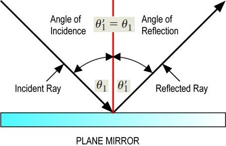
2 Reflection Law
3 Images Formed by Mirrors 1. Images Formed by Flat Mirrors 2. Images Formed by Spherical Mirrors a- Concave Mirrors b- Convex Mirrors Images Formed by Thin Lenses
4 Images are classified as: * real image is formed when light rays pass through and diverge from the image point. * virtual image is formed when the light rays do not pass through the image point but only appear to diverge from that point.
5 1. Images Formed by Flat Mirrors, cont. p :object distance q : image distance Point [ I ] is called the image of the object at [O]
6 Flat mirror has the following properties: 1. The image is as far behind the mirror as the object is in front. p = q 2. The image is unmagnified, virtual, and upright. (By upright we mean that, if the object arrow points upward so does the image arrow.) 3. The image has front back reversal.
7 Note: a flat mirror produces an image that has an apparent left right reversal. You can see this reversal by standing in front of a mirror and raising your right hand.
8 Magicians Optical
9 2. Images Formed by Spherical Mirrors Spherical Mirrors are classified as: 1- Concave Mirrors that is, one silvered so that light is reflected from the inner, concave surface. This is sometimes called a converging mirror.
10 2. Images Formed by Spherical Mirrors Spherical Mirrors are classified as: 2- Convex Mirrors that is, one silvered so that light is reflected from the outer, convex surface. This is sometimes called a diverging mirror.
11 The component of the Spherical Mirrors is : R: the mirror radius of curvature C: center of curvature V : the center of the mirror. The line through C and V is called the principal axis of the mirror.
12 - Other component of the Spherical Mirrors.V F : the focal point, which depends only on the curvature of the mirror and not on the material from which the mirror is made. The line through F and V is called the focal length f, which represents the image distance that corresponds to an infinite object distance.
13 Ray Diagrams for Mirrors Ray 1 is drawn from the top of the object parallel to the principal axis and is reflected through the focal point F. Ray 2 is drawn from the top of the object through the focal point and is reflected parallel to the principal axis. Ray 3 is drawn from the top of the object through the center of curvature C and is reflected back on itself.
14 2.1 Images Formed by Concave Mirrors
15 2.1 Images Formed by Concave Mirrors
16 2.2 Images Formed by Convex Mirrors

17 Quick Quiz: You wish to start a fire by reflecting sunlight from a mirror onto some paper under a pile of wood. Which would be the best choice for the type of mirror? (a) flat (b) concave (c) convex

 The mirror is convex and the image is real.")
18 Quick Quiz Based on the appearance of this image, you would conclude that (a) the mirror is concave and the image is real. (b) the mirror is concave and the image is virtual. (c) The mirror is convex and the image is real. (d) the mirror is convex and the image is virtual. The Hubble Space Telescope primary mirror.
19
20
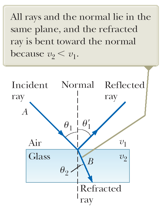
21 Refraction
22 3. Images Formed by Thin Lenses Lenses are commonly used to form images by refraction in optical instruments such as cameras, telescopes, and microscopes. F 2 F 1
23 Shapes of Lens Converging lens Diverging lens
24
25
26 Ray Diagrams for a converging lens Ray 1 is drawn parallel to the principal axis. After being refracted by the lens, this ray passes through the focal point on the back side of the lens. Ray 2 is drawn through the center of the lens and continues in a straight line. Ray 3 is drawn through the focal point on the front side of the lens (or as if coming from the focal point if p < f ) and emerges from the lens parallel to the principal axis.
27 Ray Diagrams for a converging lens

28
29 Ray Diagrams for a diverging lens Ray 1 is drawn parallel to the principal axis. After being refracted by the lens, this ray emerges directed away from the focal point on the front side of the lens. Ray 2 is drawn through the center of the lens and continues in a straight line. Ray 3 is drawn in the direction toward the focal point on the back side of the lens and emerges from the lens parallel to the principal axis.
30 Ray Diagrams for a diverging lens
31 Mirror & Lens Equation Were p is the object distance. q is the image distance. f is the focal length.
32 Magnification Equation )M( of an image for Mirror & Lens Where h is image height h is object height For plane Mirrors M = 1
33 Sign Conventions for Mirrors & lenses Quantity Positive When Negative When Image location (q) Focal length (f ) Magnification (M) real image Converging Mirror \ lenses Image is upright virtual image Diverging Mirror \ lenses Image is inverted
34 Example An automobile rearview mirror shows an image of a truck located 10.0 m from the mirror. The focal length of the mirror is m. (A) Find the position of the image of the truck. (B) Find the magnification of the image.
35 Example A spherical mirror has a focal length of cm. (a) Locate and describe the image for an object distance of 25.0 cm. (b) Locate and describe the image for an object distance of 10.0 cm. (c) Locate and describe the image for an object distance of 5.00 cm.
36 Example: Images Formed by a Converging Lens A converging lens of focal length 10.0 cm forms images of objects placed (A) 30.0 cm, (B) 10.0 cm, and (C) 5.00 cm from the lens. In each case, construct a ray diagram, find the image distance and describe the image.
Geometric Optics Converging Lenses and Mirrors Physics Lab IV
 Objective Geometric Optics Converging Lenses and Mirrors Physics Lab IV In this set of lab exercises, the basic properties geometric optics concerning converging lenses and mirrors will be explored. The
Convex Mirrors. Ray Diagram for Convex Mirror
 Convex Mirrors Center of curvature and focal point both located behind mirror The image for a convex mirror is always virtual and upright compared to the object A convex mirror will reflect a set of parallel
1. You stand two feet away from a plane mirror. How far is it from you to your image? a. 2.0 ft c. 4.0 ft b. 3.0 ft d. 5.0 ft
 Lenses and Mirrors 1. You stand two feet away from a plane mirror. How far is it from you to your image? a. 2.0 ft c. 4.0 ft b. 3.0 ft d. 5.0 ft 2. Which of the following best describes the image from
Thin Lenses Drawing Ray Diagrams
 Drawing Ray Diagrams Fig. 1a Fig. 1b In this activity we explore how light refracts as it passes through a thin lens. Eyeglasses have been in use since the 13 th century. In 1610 Galileo used two lenses
EXPERIMENT 6 OPTICS: FOCAL LENGTH OF A LENS
 EXPERIMENT 6 OPTICS: FOCAL LENGTH OF A LENS The following website should be accessed before coming to class. Text reference: pp189-196 Optics Bench a) For convenience of discussion we assume that the light
waves rays Consider rays of light from an object being reflected by a plane mirror (the rays are diverging): mirror object
: mirror object") PHYS1000 Optics 1 Optics Light and its interaction with lenses and mirrors. We assume that we can ignore the wave properties of light. waves rays We represent the light as rays, and ignore diffraction.
PHYS1000 Optics 1 Optics Light and its interaction with lenses and mirrors. We assume that we can ignore the wave properties of light. waves rays We represent the light as rays, and ignore diffraction.
Lecture 17. Image formation Ray tracing Calculation. Lenses Convex Concave. Mirrors Convex Concave. Optical instruments
 Lecture 17. Image formation Ray tracing Calculation Lenses Convex Concave Mirrors Convex Concave Optical instruments Image formation Laws of refraction and reflection can be used to explain how lenses
Lesson 29: Lenses. Double Concave. Double Convex. Planoconcave. Planoconvex. Convex meniscus. Concave meniscus
 Lesson 29: Lenses Remembering the basics of mirrors puts you half ways towards fully understanding lenses as well. The same sort of rules apply, just with a few modifications. Keep in mind that for an
Chapter 36 - Lenses. A PowerPoint Presentation by Paul E. Tippens, Professor of Physics Southern Polytechnic State University
 Chapter 36 - Lenses A PowerPoint Presentation by Paul E. Tippens, Professor of Physics Southern Polytechnic State University 2007 Objectives: After completing this module, you should be able to: Determine
C) D) As object AB is moved from its present position toward the left, the size of the image produced A) decreases B) increases C) remains the same
 D) As object AB is moved from its present position toward the left, the size of the image produced A) decreases B) increases C) remains the same") 1. For a plane mirror, compared to the object distance, the image distance is always A) less B) greater C) the same 2. Which graph best represents the relationship between image distance (di) and object
1. For a plane mirror, compared to the object distance, the image distance is always A) less B) greater C) the same 2. Which graph best represents the relationship between image distance (di) and object
HOMEWORK 4 with Solutions
 Winter 996 HOMEWORK 4 with Solutions. ind the image of the object for the single concave mirror system shown in ig. (see next pages for worksheets) by: (a) measuring the radius R and calculating the focal
Chapter 23. The Reflection of Light: Mirrors
 Chapter 23 The Reflection of Light: Mirrors Wave Fronts and Rays Defining wave fronts and rays. Consider a sound wave since it is easier to visualize. Shown is a hemispherical view of a sound wave emitted
RAY OPTICS II 7.1 INTRODUCTION
 7 RAY OPTICS II 7.1 INTRODUCTION This chapter presents a discussion of more complicated issues in ray optics that builds on and extends the ideas presented in the last chapter (which you must read first!)
2) A convex lens is known as a diverging lens and a concave lens is known as a converging lens. Answer: FALSE Diff: 1 Var: 1 Page Ref: Sec.
 A convex lens is known as a diverging lens and a concave lens is known as a converging lens. Answer: FALSE Diff: 1 Var: 1 Page Ref: Sec.") Physics for Scientists and Engineers, 4e (Giancoli) Chapter 33 Lenses and Optical Instruments 33.1 Conceptual Questions 1) State how to draw the three rays for finding the image position due to a thin
Physics for Scientists and Engineers, 4e (Giancoli) Chapter 33 Lenses and Optical Instruments 33.1 Conceptual Questions 1) State how to draw the three rays for finding the image position due to a thin
1 of 9 2/9/2010 3:38 PM
 1 of 9 2/9/2010 3:38 PM Chapter 23 Homework Due: 8:00am on Monday, February 8, 2010 Note: To understand how points are awarded, read your instructor's Grading Policy. [Return to Standard Assignment View]
Solution Derivations for Capa #14
 Solution Derivations for Capa #4 ) An image of the moon is focused onto a screen using a converging lens of focal length (f = 34.8 cm). The diameter of the moon is 3.48 0 6 m, and its mean distance from
Lecture Notes for Chapter 34: Images
 Lecture Notes for hapter 4: Images Disclaimer: These notes are not meant to replace the textbook. Please report any inaccuracies to the professor.. Spherical Reflecting Surfaces Bad News: This subject
9/16 Optics 1 /11 GEOMETRIC OPTICS
 9/6 Optics / GEOMETRIC OPTICS PURPOSE: To review the basics of geometric optics and to observe the function of some simple and compound optical devices. APPARATUS: Optical bench, lenses, mirror, target
Experiment 3 Lenses and Images
 Experiment 3 Lenses and Images Who shall teach thee, unless it be thine own eyes? Euripides (480?-406? BC) OBJECTIVES To examine the nature and location of images formed by es. THEORY Lenses are frequently
Chapter 17: Light and Image Formation
 Chapter 17: Light and Image Formation 1. When light enters a medium with a higher index of refraction it is A. absorbed. B. bent away from the normal. C. bent towards from the normal. D. continues in the
Procedure: Geometrical Optics. Theory Refer to your Lab Manual, pages 291 294. Equipment Needed
 Theory Refer to your Lab Manual, pages 291 294. Geometrical Optics Equipment Needed Light Source Ray Table and Base Three-surface Mirror Convex Lens Ruler Optics Bench Cylindrical Lens Concave Lens Rhombus
Rutgers Analytical Physics 750:228, Spring 2016 ( RUPHY228S16 )
") 1 of 13 2/17/2016 5:28 PM Signed in as Weida Wu, Instructor Help Sign Out Rutgers Analytical Physics 750:228, Spring 2016 ( RUPHY228S16 ) My Courses Course Settings University Physics with Modern Physics,
1 of 13 2/17/2016 5:28 PM Signed in as Weida Wu, Instructor Help Sign Out Rutgers Analytical Physics 750:228, Spring 2016 ( RUPHY228S16 ) My Courses Course Settings University Physics with Modern Physics,
Lesson 26: Reflection & Mirror Diagrams
 Lesson 26: Reflection & Mirror Diagrams The Law of Reflection There is nothing really mysterious about reflection, but some people try to make it more difficult than it really is. All EMR will reflect
Chapter 22: Mirrors and Lenses
 Chapter 22: Mirrors and Lenses How do you see sunspots? When you look in a mirror, where is the face you see? What is a burning glass? Make sure you know how to:. Apply the properties of similar triangles;
LIGHT REFLECTION AND REFRACTION
 QUESTION BANK IN SCIENCE CLASS-X (TERM-II) 10 LIGHT REFLECTION AND REFRACTION CONCEPTS To revise the laws of reflection at plane surface and the characteristics of image formed as well as the uses of reflection
Chapter 27 Optical Instruments. 27.1 The Human Eye and the Camera 27.2 Lenses in Combination and Corrective Optics 27.3 The Magnifying Glass
 Chapter 27 Optical Instruments 27.1 The Human Eye and the Camera 27.2 Lenses in Combination and Corrective Optics 27.3 The Magnifying Glass Figure 27 1 Basic elements of the human eye! Light enters the
Size Of the Image Nature Of the Image At Infinity At the Focus Highly Diminished, Point Real and Inverted
 CHAPTER-10 LIGHT REFLECTION AND REFRACTION Light rays; are; electromagnetic in nature, and do not need material medium for Propagation Speed of light in vacuum in 3*10 8 m/s When a light ray falls on a
AP Physics B Ch. 23 and Ch. 24 Geometric Optics and Wave Nature of Light
 AP Physics B Ch. 23 and Ch. 24 Geometric Optics and Wave Nature of Light Name: Period: Date: MULTIPLE CHOICE. Choose the one alternative that best completes the statement or answers the question. 1) Reflection,
OPTICAL IMAGES DUE TO LENSES AND MIRRORS *
 1 OPTICAL IMAGES DUE TO LENSES AND MIRRORS * Carl E. Mungan U.S. Naval Academy, Annapolis, MD ABSTRACT The properties of real and virtual images formed by lenses and mirrors are reviewed. Key ideas are
Revision problem. Chapter 18 problem 37 page 612. Suppose you point a pinhole camera at a 15m tall tree that is 75m away.
 Revision problem Chapter 18 problem 37 page 612 Suppose you point a pinhole camera at a 15m tall tree that is 75m away. 1 Optical Instruments Thin lens equation Refractive power Cameras The human eye Combining
Geometrical Optics - Grade 11
 OpenStax-CNX module: m32832 1 Geometrical Optics - Grade 11 Rory Adams Free High School Science Texts Project Mark Horner Heather Williams This work is produced by OpenStax-CNX and licensed under the Creative
Physics 25 Exam 3 November 3, 2009
 1. A long, straight wire carries a current I. If the magnetic field at a distance d from the wire has magnitude B, what would be the the magnitude of the magnetic field at a distance d/3 from the wire,
7.2. Focusing devices: Unit 7.2. context. Lenses and curved mirrors. Lenses. The language of optics
 context 7.2 Unit 7.2 ocusing devices: Lenses and curved mirrors Light rays often need to be controlled and ed to produce s in optical instruments such as microscopes, cameras and binoculars, and to change
Light and its effects
 Light and its effects Light and the speed of light Shadows Shadow films Pinhole camera (1) Pinhole camera (2) Reflection of light Image in a plane mirror An image in a plane mirror is: (i) the same size
Basic Optics System OS-8515C
 40 50 30 60 20 70 10 80 0 90 80 10 20 70 T 30 60 40 50 50 40 60 30 C 70 20 80 10 90 90 0 80 10 70 20 60 50 40 30 Instruction Manual with Experiment Guide and Teachers Notes 012-09900B Basic Optics System
Physics 116. Nov 4, 2011. Session 22 Review: ray optics. R. J. Wilkes Email: ph116@u.washington.edu
 Physics 116 Session 22 Review: ray optics Nov 4, 2011 R. J. Wilkes Email: ph116@u.washington.edu ! Exam 2 is Monday!! All multiple choice, similar to HW problems, same format as Exam 1!!! Announcements
Physics, Chapter 38: Mirrors and Lenses
 University of Nebraska - Lincoln DigitalCommons@University of Nebraska - Lincoln Robert Katz Publications Research Papers in Physics and Astronomy 1-1-1958 Physics, Chapter 38: Mirrors and Lenses Henry
LIGHT SECTION 6-REFRACTION-BENDING LIGHT From Hands on Science by Linda Poore, 2003.
 LIGHT SECTION 6-REFRACTION-BENDING LIGHT From Hands on Science by Linda Poore, 2003. STANDARDS: Students know an object is seen when light traveling from an object enters our eye. Students will differentiate
1051-232 Imaging Systems Laboratory II. Laboratory 4: Basic Lens Design in OSLO April 2 & 4, 2002
 05-232 Imaging Systems Laboratory II Laboratory 4: Basic Lens Design in OSLO April 2 & 4, 2002 Abstract: For designing the optics of an imaging system, one of the main types of tools used today is optical
Reflection and Refraction
 Equipment Reflection and Refraction Acrylic block set, plane-concave-convex universal mirror, cork board, cork board stand, pins, flashlight, protractor, ruler, mirror worksheet, rectangular block worksheet,
Light and Sound. Pupil Booklet
 Duncanrig Secondary School East Kilbride S2 Physics Elective Light and Sound Name: Pupil Booklet Class: SCN 3-11a - By exploring the refraction of light when passed through different materials, lenses
Third Grade Light and Optics Assessment
 Third Grade Light and Optics Assessment 1a. Light travels at an amazingly high speed. How fast does it travel? a. 186,000 miles per second b. 186,000 miles per hour 1b. Light travels at an amazingly high
Lenses and Telescopes
 A. Using single lenses to form images Lenses and Telescopes The simplest variety of telescope uses a single lens. The image is formed at the focus of the telescope, which is simply the focal plane of the
Study Guide for Exam on Light
 Name: Class: Date: Study Guide for Exam on Light Multiple Choice Identify the choice that best completes the statement or answers the question. 1. Which portion of the electromagnetic spectrum is used
Laws; of Refraction. bends away from the normal. more dense medium bends towards the normal. to another does not bend. It is not
 Science 8 Laws; of Refraction 1. tight that moyes at an angle from a less dense medium to a more dense medium bends towards the normal. (The second medium slows the light down) Note: The angle of refraction,
Science In Action 8 Unit C - Light and Optical Systems. 1.1 The Challenge of light
 1.1 The Challenge of light 1. Pythagoras' thoughts about light were proven wrong because it was impossible to see A. the light beams B. dark objects C. in the dark D. shiny objects 2. Sir Isaac Newton
UNIVERSITY OF SASKATCHEWAN Department of Physics and Engineering Physics
 UNIVERSITY OF SASKATCHEWAN Department of Physics and Engineering Physics Physics 111.6 MIDTERM TEST #4 March 15, 2007 Time: 90 minutes NAME: (Last) Please Print (Given) STUDENT NO.: LECTURE SECTION (please
Optics and Geometry. with Applications to Photography Tom Davis tomrdavis@earthlink.net http://www.geometer.org/mathcircles November 15, 2004
 Optics and Geometry with Applications to Photography Tom Davis tomrdavis@earthlink.net http://www.geometer.org/mathcircles November 15, 2004 1 Useful approximations This paper can be classified as applied
19 - RAY OPTICS Page 1 ( Answers at the end of all questions )
") 19 - RAY OPTICS Page 1 1 ) A ish looking up through the water sees the outside world contained in a circular horizon. I the reractive index o water is 4 / 3 and the ish is 1 cm below the surace, the radius
19 - RAY OPTICS Page 1 1 ) A ish looking up through the water sees the outside world contained in a circular horizon. I the reractive index o water is 4 / 3 and the ish is 1 cm below the surace, the radius
Lesson. Objectives. Compare how plane, convex, and concave. State the law of reflection.
 KH_BD1_SEG5_U4C12L3_407-415.indd 407 Essential Question How Do Lenses and Mirrors Affect Light? What reflective surfaces do you see in your classroom? What are the different properties of these surfaces
How to make a Galileian Telescope
 How to make a Galileian Telescope I. THE BASICS THE PRINCIPLES OF OPTICS A Galileian telescope uses just two lenses. The objective lens is convergent (plano-convex), the ocular lens is divergent (plano-concave).
Light Energy OBJECTIVES
 11 Light Energy Can you read a book in the dark? If you try to do so, then you will realize, how much we are dependent on light. Light is very important part of our daily life. We require light for a number
Vision Correction in Camera Viewfinders
 Vision Correction in Camera Viewfinders Douglas A. Kerr Issue 2 March 23, 2015 ABSTRACT AND INTRODUCTION Many camera viewfinders are equipped with a lever or knob that controls adjustable vision correction,
PHYSICS PAPER 1 (THEORY)
") PHYSICS PAPER 1 (THEORY) (Three hours) (Candidates are allowed additional 15 minutes for only reading the paper. They must NOT start writing during this time.) ---------------------------------------------------------------------------------------------------------------------
PHYSICS PAPER 1 (THEORY) (Three hours) (Candidates are allowed additional 15 minutes for only reading the paper. They must NOT start writing during this time.) ---------------------------------------------------------------------------------------------------------------------
Physics 202 Problems - Week 8 Worked Problems Chapter 25: 7, 23, 36, 62, 72
 Physics 202 Problems - Week 8 Worked Problems Chapter 25: 7, 23, 36, 62, 72 Problem 25.7) A light beam traveling in the negative z direction has a magnetic field B = (2.32 10 9 T )ˆx + ( 4.02 10 9 T )ŷ
Geometry Chapter 1. 1.1 Point (pt) 1.1 Coplanar (1.1) 1.1 Space (1.1) 1.2 Line Segment (seg) 1.2 Measure of a Segment
 1.1 Coplanar (1.1) 1.1 Space (1.1) 1.2 Line Segment (seg) 1.2 Measure of a Segment") Geometry Chapter 1 Section Term 1.1 Point (pt) Definition A location. It is drawn as a dot, and named with a capital letter. It has no shape or size. undefined term 1.1 Line A line is made up of points
Geometry Chapter 1 Section Term 1.1 Point (pt) Definition A location. It is drawn as a dot, and named with a capital letter. It has no shape or size. undefined term 1.1 Line A line is made up of points
The light. Light (normally spreads out straight... ... and into all directions. Refraction of light
 The light Light (normally spreads out straight...... and into all directions. Refraction of light But when a light ray passes from air into glas or water (or another transparent medium), it gets refracted
Physical Science Study Guide Unit 7 Wave properties and behaviors, electromagnetic spectrum, Doppler Effect
 Objectives: PS-7.1 Physical Science Study Guide Unit 7 Wave properties and behaviors, electromagnetic spectrum, Doppler Effect Illustrate ways that the energy of waves is transferred by interaction with
Lens Equation Purpose
 Lens Equation Purpose To verify the lens equation for both a converging lens and a diverging lens. To investigate optical systems. To find the focal lengths of a converging lens and a diverging lens. Background
Practice final for Basic Physics spring 2005 answers on the last page Name: Date:
 Practice final for Basic Physics spring 2005 answers on the last page Name: Date: 1. A 12 ohm resistor and a 24 ohm resistor are connected in series in a circuit with a 6.0 volt battery. Assuming negligible
7 Light and Geometric Optics
 7 Light and Geometric Optics By the end of this chapter, you should be able to do the following: Use ray diagrams to analyse situations in which light reflects from plane and curved mirrors state the law
First let us consider microscopes. Human eyes are sensitive to radiation having wavelengths between
 Optical Differences Between Telescopes and Microscopes Robert R. Pavlis, Girard, Kansas USA icroscopes and telescopes are optical instruments that are designed to permit observation of objects and details
Physical Science 20 - Final Exam Practice
 Physical Science 20 - Final Exam Practice SHORT ANSWER IS ALL CURVED MIRRORS AND LENSES Mirrors and Lenses 1. Complete the following ray diagrams for curved mirrors. Write the 4 characteristics of each
Learning Optics using Vision
 Learning Optics using Vision Anjul Maheshwari David R. Williams Biomedical Engineering Center for Visual Science University of Rochester Rochester, NY Center for Adaptive Optics Project #42 2 INTRODUCTION
Review for Test 3. Polarized light. Action of a Polarizer. Polarized light. Light Intensity after a Polarizer. Review for Test 3.
 Review for Test 3 Polarized light No equation provided! Polarized light In linearly polarized light, the electric field vectors all lie in one single direction. Action of a Polarizer Transmission axis
Introduction. In Physics light is referred to as electromagnetic radiation which is a natural phenomenon that can
 Introduction In Physics light is referred to as electromagnetic radiation which is a natural phenomenon that can also be produced and detected through technological means. It has proven invaluable for
3D Printing LESSON PLAN PHYSICS 8,11: OPTICS
 INVESTIGATE RATIONALE Optics is commonly taught through the use of commercial optics kits that usually include a basic set of 2-4 geometric lenses (such as double convex or double concave). These lenses
Optical Communications
 Optical Communications Telecommunication Engineering School of Engineering University of Rome La Sapienza Rome, Italy 2005-2006 Lecture #2, May 2 2006 The Optical Communication System BLOCK DIAGRAM OF
Section 13.3 Telescopes and Microscopes
 Glass correcting plate Secondary Finder scope ive Diagonal prism Equatorial drive Equatorial mount Section 13.3 Telescopes and Microscopes Tripod Not everything that we wish to see is visible to the naked
potential in the centre of the sphere with respect to infinity.
 Umeå Universitet, Fysik 1 Vitaly Bychkov Prov i fysik, Electricity and Waves, 2006-09-27, kl 16.00-22.00 Hjälpmedel: Students can use any book. Define the notations you are using properly. Present your
EXPERIMENT O-6. Michelson Interferometer. Abstract. References. Pre-Lab
 EXPERIMENT O-6 Michelson Interferometer Abstract A Michelson interferometer, constructed by the student, is used to measure the wavelength of He-Ne laser light and the index of refraction of a flat transparent
Endoscope Optics. Chapter 8. 8.1 Introduction
 Chapter 8 Endoscope Optics Endoscopes are used to observe otherwise inaccessible areas within the human body either noninvasively or minimally invasively. Endoscopes have unparalleled ability to visualize
Lecture 12: Cameras and Geometry. CAP 5415 Fall 2010
 Lecture 12: Cameras and Geometry CAP 5415 Fall 2010 The midterm What does the response of a derivative filter tell me about whether there is an edge or not? Things aren't working Did you look at the filters?
PHYSICS 534 (Revised Edition 2001)
") Student Study Guide PHYSICS 534 (Revised Edition 2001) Leonardo da Vinci 1452-1519 Student Study Guide Physics 534 (Revised Edition - 2000) This Study Guide was written by a committee of Physics teachers
Student Study Guide PHYSICS 534 (Revised Edition 2001) Leonardo da Vinci 1452-1519 Student Study Guide Physics 534 (Revised Edition - 2000) This Study Guide was written by a committee of Physics teachers
The Vertex Power of Ophthalmic Lenses
 The Vertex Power of Ophthalmic Lenses Douglas A. Kerr Issue 6 December 7, 2010 ABSTRACT The ability of a lens to converge or diverge rays of light that arrive on separate, parallel paths is quantified
Chapter 6 Telescopes: Portals of Discovery. How does your eye form an image? Refraction. Example: Refraction at Sunset.
 Chapter 6 Telescopes: Portals of Discovery 6.1 Eyes and Cameras: Everyday Light Sensors Our goals for learning:! How does your eye form an image?! How do we record images? How does your eye form an image?
Magnification Devices
 LOW VISION AIDS Optical Characteristics of the Low Vision Patient The definition of visual loss includes two components and limited resolving power or acuity, a blur that can't be eliminated with a simple
Light Telescopes. Grade Level: 5. 2-3 class periods (more if in-depth research occurs)
") Light Telescopes Grade Level: 5 Time Required: Suggested TEKS: Science - 5.4 Suggested SCANS Information. Acquires and evaluates information. National Science and Math Standards Science as Inquiry, Earth
Light Telescopes Grade Level: 5 Time Required: Suggested TEKS: Science - 5.4 Suggested SCANS Information. Acquires and evaluates information. National Science and Math Standards Science as Inquiry, Earth
PHYS 222 Spring 2012 Final Exam. Closed books, notes, etc. No electronic device except a calculator.
 PHYS 222 Spring 2012 Final Exam Closed books, notes, etc. No electronic device except a calculator. NAME: (all questions with equal weight) 1. If the distance between two point charges is tripled, the
Understanding astigmatism Spring 2003
 MAS450/854 Understanding astigmatism Spring 2003 March 9th 2003 Introduction Spherical lens with no astigmatism Crossed cylindrical lenses with astigmatism Horizontal focus Vertical focus Plane of sharpest
Information. From the LowVision Specialists. Guidelines for the fitting of telescopic systems
 Information From the LowVision Specialists Guidelines for the fitting of telescopic systems About a successful fitting Eye care professionals dispensing telescopic spectacles must ensure they have successfully
Measuring Miniature Lens Radius of Curvature and Refractive Index with White Light Optical Profiler
 Measuring Miniature Lens Radius of Curvature and Refractive Index with White Light Optical Profiler Introduction For miniature lenses with size of few millimeters or sub-millimeter, it is difficult to
Testing and Performance of the Convex Lens Concentrating Solar Power Panel Prototype
 Testing and Performance of the Convex Lens Concentrating Solar Power Panel Prototype Ankit S. Gujrathi 1, Prof. Dilip Gehlot 2 1 M.tech (2 nd Year), 2 Assistant Professor, Department of Mechanical Engg.,
Making A Mirror Grinding Tool By Allen Malsburry
 Making A Mirror Grinding Tool By Allen Malsburry The average person would never think, I can make my own telescope. Most amateur astronomers believe, I can buy a better telescope than I can build. Neither
Making a reflector telescope
 Making a reflector telescope telescope built by Sir Isaac Newton Replica of the first reflector Nowadays, professional astronomers use another type of telescope that is different to the first telescope
Optics. Kepler's telescope and Galileo's telescope. f 1. f 2. LD Physics Leaflets P5.1.4.2. Geometrical optics Optical instruments
 Optics Geometrical optics Optical instruments LD Physics Lealets P5.1.4.2 Kepler's telescope and Galileo's telescope Objects o the experiment g Veriying that the length o a telescope is given by the sum
Basic Geometrical Optics
 F UNDAMENTALS OF PHOTONICS Module 1.3 Basic Geometrical Optics Leno S. Pedrotti CORD Waco, Texas Optics is the cornerstone of photonics systems and applications. In this module, you will learn about one
Lenses and Apertures of A TEM
 Instructor: Dr. C.Wang EMA 6518 Course Presentation Lenses and Apertures of A TEM Group Member: Anup Kr. Keshri Srikanth Korla Sushma Amruthaluri Venkata Pasumarthi Xudong Chen Outline Electron Optics
How To Understand General Relativity
 Chapter S3 Spacetime and Gravity What are the major ideas of special relativity? Spacetime Special relativity showed that space and time are not absolute Instead they are inextricably linked in a four-dimensional
Std. XI Science Physics Practical Handbook
 Std. XI Science Physics Practical Handbook No. Experiments Page No. 1 Use of Vernier Callipers 1 2 Use of Micrometer screw gauge 5 3 Use of Spherometer 9 4 Parallelogram law of forces 12 5 Coefficient
Teacher s Resource. 2. The student will see the images reversed left to right.
 Answer Booklet Reflection of Light With a Plane (Flat) Mirror Trace a Star Page 16 1. The individual students will complete the activity with varying degrees of difficulty. 2. The student will see the
PH3FP. (JUn13PH3Fp01) General Certificate of Secondary Education Foundation Tier June 2013. Unit Physics P3 TOTAL. Time allowed 1 hour
 General Certificate of Secondary Education Foundation Tier June 2013. Unit Physics P3 TOTAL. Time allowed 1 hour") Centre Number Surname Candidate Number For Examiner s Use Other Names Candidate Signature Examiner s Initials Physics Unit Physics P3 Thursday 23 May 2013 For this paper you must have: a ruler a calculator
Centre Number Surname Candidate Number For Examiner s Use Other Names Candidate Signature Examiner s Initials Physics Unit Physics P3 Thursday 23 May 2013 For this paper you must have: a ruler a calculator
Physics 1230: Light and Color
 Physics 1230: Light and Color The Eye: Vision variants and Correction http://www.colorado.edu/physics/phys1230 What does 20/20 vision mean? Visual acuity is usually measured with a Snellen chart Snellen
Aspherical Lens Design by Using a Numerical Analysis
 Journal of the Korean Physical Society, Vol. 51, No. 1, July 27, pp. 93 13 Aspherical Lens Design by Using a Numerical Analysis Gyeong-Il Kweon Department of Optoelectronics, Honam University, Gwangju
Physics 30 Worksheet # 14: Michelson Experiment
 Physics 30 Worksheet # 14: Michelson Experiment 1. The speed of light found by a Michelson experiment was found to be 2.90 x 10 8 m/s. If the two hills were 20.0 km apart, what was the frequency of the
Optical Design using Fresnel Lenses
 Optical Design using Fresnel Lenses Basic principles and some practical examples Arthur Davis and Frank Kühnlenz Reflexite Optical Solutions Business Abstract The fresnel lens can be used in a wide variety
Code number given on the right hand side of the question paper should be written on the title page of the answerbook by the candidate.
 Series ONS SET-1 Roll No. Candiates must write code on the title page of the answer book Please check that this question paper contains 16 printed pages. Code number given on the right hand side of the
Forensic Science: The Basics. Microscopy
 Forensic Science: The Basics Microscopy Chapter 6 Jay A. Siegel,Ph.D. Power point presentation by Greg Galardi, Peru State College, Peru Nebraska Presentation by Greg Galardi, Peru State College CRC Press,
White paper. Sharpdome. Sharp images on every level
 White paper Sharpdome Sharp images on every level Table of contents 1. Introduction 3 2. Conventional dome limitations 3 2.1 L-value 4 3. Sharpdome 5 3.1 Transparent covering material 6 3.2 Axis Speed
PHYS 39a Lab 3: Microscope Optics
 PHYS 39a Lab 3: Microscope Optics Trevor Kafka December 15, 2014 Abstract In this lab task, we sought to use critical illumination and Köhler illumination techniques to view the image of a 1000 lines-per-inch