Electron Microscopy (MM-535)
|
|
|
- Georgia Ray
- 9 years ago
- Views:
Transcription
1 1
2 Electron Microscopy (MM-535) MUHAMMAD SAJID ALI ASGHAR (Lecturer) 2 Department of Materials Engineering NED University of Engineering and Technology Karachi
3 Microscopy with Light and Electrons A microscope is an optical / visual system which transforms an object into an image. We are usually interested in making the image much larger than the object, that is magnifying it, and there are many ways in which this can be done. 1. Light Microscope 2. Electron Microscope 3
4 Methods of image formation There are three basic ways in which an image can be formed. Perhaps the simplest to imagine is the projection image, of which the commonest example is the formation of shadows when an object is placed in front of a point source of illumination, as shown in Figure 1.1. Figure 1.1 The formation of a projection (or shadow) image. Each point in the object is projected directly at the equivalent point in the image. 4
5 Methods of image formation The second type of image is formed by conventional lens systems, as for example in Figure 1.2, and we shall call this an optical image. 5 Figure 1.2 a single convex lens or 'magnifying glass'. The ray diagram for this is shown in Figure.
6 Magnifying glass A magnifying glass, is a single convex lens which is used to produce a magnified image of an object. The lens is usually mounted in a frame with a handle. The magnification of a magnifying glass is typically up to 10X 6
7 Methods of image formation Both projection and optical images are formed in parallel, that is all parts of the image are formed essentially simultaneously. However the third type of image we need to consider is the scanning image, in which each point of the picture is presented serially. The best-known example of this type of image is a television picture, in which several thousand picture points are displayed consecutively, but the process is repeated with such a high frequency that the image appears to the eye in its totality. 7
8 Pixels The smallest piece of information about the image is contained in one of these picture points. They are generally called pixels. Which is short for picture element. A single domestic TV picture therefore consists of more than pixels, each of which can be of a different intensity or colour. The smallest detail which can possibly be shown in the image is a single pixel in size. 8
9 Pixels the images produced by electron microscopes are stored in computer memory and need to be in a digital form, that is each pixel is coded Such images are often composed of a number of pixels which is a power of two, and common image sizes are 256 x 256 (= 2 8 x 2 8 ) pixels or 1024 x 1024 (= 2 10 X 2 10 ) pixels. Large amounts of computer memory are then needed to store such images. 9
10 The Light-Optical Microscope The first lens, the objective, provides an inverted image at B with a magnification (V1 f1)if1 and the second lens, the projector, gives a final upright image at a further magnification of (V2 - f2)//2. The image is viewed on a screen or recorded on a photographic plate at C with a total magnification of Figure 1.3 The ray diagram of a simple two-stage projection microscrope. The object 10 is at 0 and the final image at C, with an intermediate image at B.
11 The Light-Optical Microscope we have a division into two classes of optical microscope: The biologist who needs to look at very thin sections of tissue uses a transmission arrangement such as that shown in Figure 1.4(a), Figure 1.4 The optical systems for the common types of projection microscope. (a) 11 Transmission illumination
12 The Light-Optical Microscope While the materials scientist or geologist who needs to examine the surface structure of a solid specimen uses a reflection arrangement as shown in Figure 1.4(b). Figure 1.4 The optical systems for the common types of projection microscope. (b) Reflected illumination. 12
13 Magnification Magnification is the process of enlarging something only in appearance, not in physical size. Magnification is also a number describing by which factor an object was magnified. (X) 13
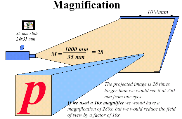
14 14 Magnification
15 Simple Magnification A typical magnifying glass consists of a single thin convex lens that produces a magnification in the range of 1.5x to 30x, with the most common being about 2-4x for reading or studying rocks, stamps, coins, insects, and leaves. Magnifying glasses produce a virtual image that is magnified The unaided human eye can easily detect detail only 0 2 mm in size. 15
16 Empty Magnification Empty magnification: increasing magnification without increasing the resolving power. Thus any magnification greater than 1000 x only makes the details bigger. We cannot make finer details visible by magnifying the image an extra ten times. This is called as the 'empty magnification', is shown in Figure
17 Empty Magnification It is not necessary to build a light microscope with three or more stages of magnification, since this will not improve the resolution but will rather degrade it by introducing extra aberrations 17
18 18 Effective Magnification
19 Resolution In order to compare the electron microscope with the light microscope we need to know what factors control the resolution (often called resolving power) Which we will define as the closest spacing of two points which can clearly be seen through the microscope to be separate entities. 19
20 Microscope Resolution Ability of a lens to separate or distinguish small objects that are close together Wavelength of light used is major factor in resolution shorter wavelength greater resolution 20
21 Resolution The ability to resolve fine details is called resolution. It is the minimum distance between two points such that the two points are perceived as separated image. R. P N. A. N. A. sin R.P.=Resolving Power, N.A=Numerical Aperture λ=wavelength of the light, β=the half acceptance angle of the lens, µ = refractive index of the lens 21

22 22 Resolving Power Line
23 Resolution The resolution limit is d 1 /2. Microscope apertures are normally referred to in terms of the semi-angle, α, which they subtend at the specimen. Where λ is the wavelength of the light μ is the refractive index of the medium between the object and the objective lens. The product, μ sin α is usually called the numerical aperture (NA). 23
24 Resolution In order to obtain the best resolution (i.e. the smallest r 1 ) it is obviously possible to decrease λ or increase μ or α. sin α can be increased towards 1 by using as large an aperture as possible and μ can be increased by using an oil immersion objective lens. 24
25 SEM over OM Mag Depth of Field Resolution OM: 4x 1400x 0.5mm ~ 0.2mm SEM: 10x 500Kx 30mm 1.5nm The SEM has a large depth of field, which allows a large amount of the sample to be in focus at one time and produces an image that is a good representation of the three-dimensional sample. The combination of higher magnification, larger depth of field, greater resolution, compositional and crystallographic information makes the SEM one of the most heavily used instruments in academic/national lab research 25 areas and industry.
26 Depth of Field The range of positions for the object for which our eye can detect no change in the sharpness of the image is known as the depth of field. In most microscopes this distance is rather small and therefore in order to produce sharp images the object must be very flat. If a non-flat object (or a transparent object of appreciable thickness) is viewed at high magnification using a light microscope then some out-of-focus regions will be seen. 26
27 Depth of Field Optical micrograph SEM micrograph 27

28 28 Depth of Field
29 29
30 Depth of Field The only effective way to increase the depth of field is to decrease the convergence angle, which is controlled in most cases by the objective aperture Figure 1.10 shows. Notice that conditions which maximize the depth of field simultaneously make the resolution worse (equation 1.4). It will become apparent later that the use of electrons for microscopy brings a number of advantages, among which are an improvement in both resolution and depth of field. The reason for this is that high energy electrons have a much smaller wavelength than light and the microscopes are usually operated with very small values of α. 30
31 31 Depth of Field
32 Depth of Focus A term which is often confused with depth of field is the depth of focus. This refers to the range of positions at which the image can be viewed without appearing out of focus, for a fixed position of the object.. it will not make any difference to the sharpness of the image if the object is anywhere within the range h shown in Figure
33 Depth of Field: OM vs SEM Optical Microscope 0.5mm 33 SEM 30mm
34 Issue: Depth of Focus OPTICAL SEM 34
35 Electrons versus Light Light as electromagnetic radiation with a wavelength λ and of electrons as atomic particles. Both types of description (wave and particle) of course apply to both light and electrons: 1.The first obvious difference between electrons and light is that their wavelengths differ by a factor of many thousands. 35 Thus light may be described in terms of photons or as radiation of wavelength nm, While electrons can also be considered as radiation with wavelengths (useful in microscopy) between about and 0 01 nm.
36 Electrons versus Light 2. Another major difference is that electrons are very much more strongly scattered by gases than is light. This is so severe an effect that in order to use electrons in a microscope all the optical paths must be evacuated to a pressure of better than 10- l opa (about 10-7 of atmospheric pressure) The electrons would scarcely penetrate a few millimetres of air at atmospheric pressure. 36
37 Electrons versus Light 3. A further major difference between electrons and light is that Electrons carry a charge. Not only does this mean that electromagnetic fields can be used as lenses for electrons but it opens up the possibility of easily scanning a beam of electrons back and forth. Both types of electron microscope, transmission and scanning, the use of electromagnetic lens But in optical microscope use of glass lens 37
38 Conclusion Electron microscopy therefore offers 1. Higher resolution, 2. Higher magnification, 3. Greater depth of field and 4. Greater versatility than the light microscope, Although at a rather higher price. 38
39 Aberrations in Optical & EM systems Resolution and depth of field it has been assumed that all the components of the microscope are perfect and will focus the light from any point on the object to a similar unique point in the image. This is in fact rather difficult to achieve because of lens aberrations. Two types of aberration Chromatic aberrations which depend on the spectrum of wavelengths in the light and monochromatic or achromatic aberrations which affect even light of a single wavelength. The effect of each aberration is to distort the image of every point in the object in a particular way, leading to an overall loss of quality and resolution in the image. 39
40 Chromatic Aberrations Chromatic aberrations occur when a range of wavelengths is present in the light (e.g. in 'white' light) Ray diagram illustrating the introduction of chromatic aberration by a single lens. light of shorter wavelength (blue) is brought to a focus nearer the lens than the longer wavelength (red) light. The smallest 'focused' spot is the disc of least confusion at C. 40
41 Aberration Corrections All aberration corrections are designed to reduce in size this disc of confusion. In the light microscope there are two ways in which chromatic aberrations can be improved, 1. Either by combining lenses of different shapes and refractive indices or By eliminating the variation in wavelength from the light source by the use of filters or special lamps. Both methods are often used if the very best resolution is required,
42 Monochromatic Aberrations Monochromatic aberrations arise because of the different path lengths of different rays from an object point to the image point. The simplest of these effects is spherical aberration All the monochromatic aberrations are reduced if only the central portion of the lens is used, i.e. if the lens aperture is 'stopped down'. 42
43 The objective aperture The objective aperture controls the convergence angle A small aperture will reduce the effect of spherical aberration (through a small) and increase the depth of focus, but will limit the beam current
44 Spherical Aberration Lens imperfections lead to different focal lengths in centre and at edges of lens 44 44
45 45
46 Distortion This will occurs if the magnification of the lens changes for rays off the optical axis. 1. The two possible cases are when magnification increases with distance from the optical axis, leading to pincushion distortion, 2. When magnification decreases with distance from the optical axis, leading to barrel distortion The appearance of a square grid in the presence of (a) barrel and (b) pincushion distortion. 46
47 47
48 Diffraction Diffraction occurs when a wavefront encounters an edge of an object. This results in the establishment of new wavefronts 48
49 Diffraction When this occurs at the edges of an aperture the diffracted waves tend to spread out the focus rather than concentrate them. This results in a decrease in resolution, the effect becoming more pronounced with ever smaller apertures. 49

50 Apertures Advantages 1. Increase contrast by blocking scattered electrons 2. Decrease effects of chromatic and spherical aberration by cutting off edges of a lens Disadvantages 1. Decrease resolution due to effects of diffraction 2. Decrease resolution by reducing half angle of illumination 3. Decrease illumination by blocking scattered electrons 50

51 Astigmatism If a lens is not completely symmetrical objects will be focused to different focal planes resulting in an astigmatic image 51
52 Astigmatism The result is a distorted image. This can best be prevented by having as near to perfect a lens as possible but other defects such as dirt on an aperture etc. can cause an astigmatism 52
53 Astigmatism Lens defect caused by magnetic field asymmetry Astigmatism The inability of the lens to bring to focus both vertical and horizontal lines on the same plane. 53 can be corrected using stigmators! 53
54 54 Aberrations
55 Stigmatism and Resolution The shape of electron beam affects SEM image resolution: when the beam is round, or without stigmatism, the image shows small features (high resolution) as seen in Fig. a; when the beam is not round, or with stigmatism, the image details become unclear (lower resolution) as seen in Fig. b. without stigmatism with stigmatism When the image has stigmatism, changing beam focus may result in elongated feature: Figs. c and d were recorded when the beam were under and over focus, respectively. 55 Under focus Over focus 55
56 Astigmatism -x&y focus at different planes -fix by adjusting stigmators 56 56
57 Assignment 1. If a small object is placed 2 mm away from a convex lens of focal length 1 mm, how far from the lens will the image be formed? 2. Where is the image produced by a thin convex lens when the object is at the focal point? 3. How many convex lenses, with focal length 1 mm and object distance (u) 1 1 mm, are needed to give a final image with magnification 1 million times? 4. In a light microscope an object is placed 2 mm away from a lens of diameter 2 mm. The object is in air (refractive index = 1) and the wavelength of the (green) light is 520 nm. What is the best possible resolving power of this microscope? 5. Calculate the position of the image and its magnification when an object is held 10 cm from a convex lens of focal length 8 cm. 6. Calculate the depth of field for a resolving power of 1 μm in a microscope with a final aperture of diameter 1 mm and a working distance of 20 mm. What is the depth of focus at a magnification of100lx? 7. If lenses with maximum useful magnifications of 40x are available, how many lenses are needed to achieve magnifications of: 100 x, x, 1 million x? 8. What are the dimensions of C s? Deduce the approximate value of C s for (a) an electron microscope capable of 0 1 nm resolution, and (b) a light microscope capable of 0 5 mm resolution. 9. Chromatic aberrations can be virtually eliminated by using electrons of a very small range of wavelengths.' Why, in a TEM, can chromatic aberrations never be 57 completely eliminated?
1. You stand two feet away from a plane mirror. How far is it from you to your image? a. 2.0 ft c. 4.0 ft b. 3.0 ft d. 5.0 ft
 Lenses and Mirrors 1. You stand two feet away from a plane mirror. How far is it from you to your image? a. 2.0 ft c. 4.0 ft b. 3.0 ft d. 5.0 ft 2. Which of the following best describes the image from
Revision problem. Chapter 18 problem 37 page 612. Suppose you point a pinhole camera at a 15m tall tree that is 75m away.
 Revision problem Chapter 18 problem 37 page 612 Suppose you point a pinhole camera at a 15m tall tree that is 75m away. 1 Optical Instruments Thin lens equation Refractive power Cameras The human eye Combining
Lenses and Apertures of A TEM
 Instructor: Dr. C.Wang EMA 6518 Course Presentation Lenses and Apertures of A TEM Group Member: Anup Kr. Keshri Srikanth Korla Sushma Amruthaluri Venkata Pasumarthi Xudong Chen Outline Electron Optics
AP Physics B Ch. 23 and Ch. 24 Geometric Optics and Wave Nature of Light
 AP Physics B Ch. 23 and Ch. 24 Geometric Optics and Wave Nature of Light Name: Period: Date: MULTIPLE CHOICE. Choose the one alternative that best completes the statement or answers the question. 1) Reflection,
Understanding astigmatism Spring 2003
 MAS450/854 Understanding astigmatism Spring 2003 March 9th 2003 Introduction Spherical lens with no astigmatism Crossed cylindrical lenses with astigmatism Horizontal focus Vertical focus Plane of sharpest
First let us consider microscopes. Human eyes are sensitive to radiation having wavelengths between
 Optical Differences Between Telescopes and Microscopes Robert R. Pavlis, Girard, Kansas USA icroscopes and telescopes are optical instruments that are designed to permit observation of objects and details
1051-232 Imaging Systems Laboratory II. Laboratory 4: Basic Lens Design in OSLO April 2 & 4, 2002
 05-232 Imaging Systems Laboratory II Laboratory 4: Basic Lens Design in OSLO April 2 & 4, 2002 Abstract: For designing the optics of an imaging system, one of the main types of tools used today is optical
View of ΣIGMA TM (Ref. 1)
") Overview of the FESEM system 1. Electron optical column 2. Specimen chamber 3. EDS detector [Electron Dispersive Spectroscopy] 4. Monitors 5. BSD (Back scatter detector) 6. Personal Computer 7. ON/STANDBY/OFF
Overview of the FESEM system 1. Electron optical column 2. Specimen chamber 3. EDS detector [Electron Dispersive Spectroscopy] 4. Monitors 5. BSD (Back scatter detector) 6. Personal Computer 7. ON/STANDBY/OFF
Chapter 4. Microscopy, Staining, and Classification. Lecture prepared by Mindy Miller-Kittrell North Carolina State University
 Chapter 4 Microscopy, Staining, and Classification 2012 Pearson Education Inc. Lecture prepared by Mindy Miller-Kittrell North Carolina State University Microscopy and Staining 2012 Pearson Education Inc.
THE COMPOUND MICROSCOPE
 THE COMPOUND MICROSCOPE In microbiology, the microscope plays an important role in allowing us to see tiny objects that are normally invisible to the naked eye. It is essential for students to learn how
Chapter 17: Light and Image Formation
 Chapter 17: Light and Image Formation 1. When light enters a medium with a higher index of refraction it is A. absorbed. B. bent away from the normal. C. bent towards from the normal. D. continues in the
Light and its effects
 Light and its effects Light and the speed of light Shadows Shadow films Pinhole camera (1) Pinhole camera (2) Reflection of light Image in a plane mirror An image in a plane mirror is: (i) the same size
2) A convex lens is known as a diverging lens and a concave lens is known as a converging lens. Answer: FALSE Diff: 1 Var: 1 Page Ref: Sec.
 A convex lens is known as a diverging lens and a concave lens is known as a converging lens. Answer: FALSE Diff: 1 Var: 1 Page Ref: Sec.") Physics for Scientists and Engineers, 4e (Giancoli) Chapter 33 Lenses and Optical Instruments 33.1 Conceptual Questions 1) State how to draw the three rays for finding the image position due to a thin
Physics for Scientists and Engineers, 4e (Giancoli) Chapter 33 Lenses and Optical Instruments 33.1 Conceptual Questions 1) State how to draw the three rays for finding the image position due to a thin
Measuring the Point Spread Function of a Fluorescence Microscope
 Frederick National Laboratory Measuring the Point Spread Function of a Fluorescence Microscope Stephen J Lockett, PhD Principal Scientist, Optical Microscopy and Analysis Laboratory Frederick National
C) D) As object AB is moved from its present position toward the left, the size of the image produced A) decreases B) increases C) remains the same
 D) As object AB is moved from its present position toward the left, the size of the image produced A) decreases B) increases C) remains the same") 1. For a plane mirror, compared to the object distance, the image distance is always A) less B) greater C) the same 2. Which graph best represents the relationship between image distance (di) and object
1. For a plane mirror, compared to the object distance, the image distance is always A) less B) greater C) the same 2. Which graph best represents the relationship between image distance (di) and object
Convex Mirrors. Ray Diagram for Convex Mirror
 Convex Mirrors Center of curvature and focal point both located behind mirror The image for a convex mirror is always virtual and upright compared to the object A convex mirror will reflect a set of parallel
waves rays Consider rays of light from an object being reflected by a plane mirror (the rays are diverging): mirror object
: mirror object") PHYS1000 Optics 1 Optics Light and its interaction with lenses and mirrors. We assume that we can ignore the wave properties of light. waves rays We represent the light as rays, and ignore diffraction.
PHYS1000 Optics 1 Optics Light and its interaction with lenses and mirrors. We assume that we can ignore the wave properties of light. waves rays We represent the light as rays, and ignore diffraction.
RAY OPTICS II 7.1 INTRODUCTION
 7 RAY OPTICS II 7.1 INTRODUCTION This chapter presents a discussion of more complicated issues in ray optics that builds on and extends the ideas presented in the last chapter (which you must read first!)
Science In Action 8 Unit C - Light and Optical Systems. 1.1 The Challenge of light
 1.1 The Challenge of light 1. Pythagoras' thoughts about light were proven wrong because it was impossible to see A. the light beams B. dark objects C. in the dark D. shiny objects 2. Sir Isaac Newton
Study Guide for Exam on Light
 Name: Class: Date: Study Guide for Exam on Light Multiple Choice Identify the choice that best completes the statement or answers the question. 1. Which portion of the electromagnetic spectrum is used
Experiment 3 Lenses and Images
 Experiment 3 Lenses and Images Who shall teach thee, unless it be thine own eyes? Euripides (480?-406? BC) OBJECTIVES To examine the nature and location of images formed by es. THEORY Lenses are frequently
LIGHT SECTION 6-REFRACTION-BENDING LIGHT From Hands on Science by Linda Poore, 2003.
 LIGHT SECTION 6-REFRACTION-BENDING LIGHT From Hands on Science by Linda Poore, 2003. STANDARDS: Students know an object is seen when light traveling from an object enters our eye. Students will differentiate
Geometric Optics Converging Lenses and Mirrors Physics Lab IV
 Objective Geometric Optics Converging Lenses and Mirrors Physics Lab IV In this set of lab exercises, the basic properties geometric optics concerning converging lenses and mirrors will be explored. The
Care and Use of the Compound Microscope
 Revised Fall 2011 Care and Use of the Compound Microscope Objectives After completing this lab students should be able to 1. properly clean and carry a compound and dissecting microscope. 2. focus a specimen
Physics 116. Nov 4, 2011. Session 22 Review: ray optics. R. J. Wilkes Email: [email protected]
 Physics 116 Session 22 Review: ray optics Nov 4, 2011 R. J. Wilkes Email: [email protected] ! Exam 2 is Monday!! All multiple choice, similar to HW problems, same format as Exam 1!!! Announcements
MICROSCOPY. To demonstrate skill in the proper utilization of a light microscope.
 MICROSCOPY I. OBJECTIVES To demonstrate skill in the proper utilization of a light microscope. To demonstrate skill in the use of ocular and stage micrometers for measurements of cell size. To recognize
DOING PHYSICS WITH MATLAB COMPUTATIONAL OPTICS RAYLEIGH-SOMMERFELD DIFFRACTION INTEGRAL OF THE FIRST KIND
 DOING PHYSICS WITH MATLAB COMPUTATIONAL OPTICS RAYLEIGH-SOMMERFELD DIFFRACTION INTEGRAL OF THE FIRST KIND THE THREE-DIMENSIONAL DISTRIBUTION OF THE RADIANT FLUX DENSITY AT THE FOCUS OF A CONVERGENCE BEAM
EXPERIMENT #1: MICROSCOPY
 EXPERIMENT #1: MICROSCOPY Brightfield Compound Light Microscope The light microscope is an important tool in the study of microorganisms. The compound light microscope uses visible light to directly illuminate
Thin Lenses Drawing Ray Diagrams
 Drawing Ray Diagrams Fig. 1a Fig. 1b In this activity we explore how light refracts as it passes through a thin lens. Eyeglasses have been in use since the 13 th century. In 1610 Galileo used two lenses
LIGHT REFLECTION AND REFRACTION
 QUESTION BANK IN SCIENCE CLASS-X (TERM-II) 10 LIGHT REFLECTION AND REFRACTION CONCEPTS To revise the laws of reflection at plane surface and the characteristics of image formed as well as the uses of reflection
Forensic Science: The Basics. Microscopy
 Forensic Science: The Basics Microscopy Chapter 6 Jay A. Siegel,Ph.D. Power point presentation by Greg Galardi, Peru State College, Peru Nebraska Presentation by Greg Galardi, Peru State College CRC Press,
EXPERIMENT 6 OPTICS: FOCAL LENGTH OF A LENS
 EXPERIMENT 6 OPTICS: FOCAL LENGTH OF A LENS The following website should be accessed before coming to class. Text reference: pp189-196 Optics Bench a) For convenience of discussion we assume that the light
WAVELENGTH OF LIGHT - DIFFRACTION GRATING
 PURPOSE In this experiment we will use the diffraction grating and the spectrometer to measure wavelengths in the mercury spectrum. THEORY A diffraction grating is essentially a series of parallel equidistant
Rodenstock Photo Optics
 Rogonar Rogonar-S Rodagon Apo-Rodagon N Rodagon-WA Apo-Rodagon-D Accessories: Modular-Focus Lenses for Enlarging, CCD Photos and Video To reproduce analog photographs as pictures on paper requires two
Physics 441/2: Transmission Electron Microscope
 Physics 441/2: Transmission Electron Microscope Introduction In this experiment we will explore the use of transmission electron microscopy (TEM) to take us into the world of ultrasmall structures. This
Physical Science Study Guide Unit 7 Wave properties and behaviors, electromagnetic spectrum, Doppler Effect
 Objectives: PS-7.1 Physical Science Study Guide Unit 7 Wave properties and behaviors, electromagnetic spectrum, Doppler Effect Illustrate ways that the energy of waves is transferred by interaction with
1 of 9 2/9/2010 3:38 PM
 1 of 9 2/9/2010 3:38 PM Chapter 23 Homework Due: 8:00am on Monday, February 8, 2010 Note: To understand how points are awarded, read your instructor's Grading Policy. [Return to Standard Assignment View]
Theremino System Theremino Spectrometer Technology
 Theremino System Theremino Spectrometer Technology theremino System - Theremino Spectrometer Technology - August 15, 2014 - Page 1 Operation principles By placing a digital camera with a diffraction grating
Microscopy. MICROSCOPY Light Electron Tunnelling Atomic Force RESOLVE: => INCREASE CONTRAST BIODIVERSITY I BIOL1051 MAJOR FUNCTIONS OF MICROSCOPES
 BIODIVERSITY I BIOL1051 Microscopy Professor Marc C. Lavoie [email protected] MAJOR FUNCTIONS OF MICROSCOPES MAGNIFY RESOLVE: => INCREASE CONTRAST Microscopy 1. Eyepieces 2. Diopter adjustment
The Basics of Scanning Electron Microscopy
 The Basics of Scanning Electron Microscopy The small scanning electron microscope is easy to use because almost every variable is pre-set: the acceleration voltage is always 15kV, it has only a single
Interference. Physics 102 Workshop #3. General Instructions
 Interference Physics 102 Workshop #3 Name: Lab Partner(s): Instructor: Time of Workshop: General Instructions Workshop exercises are to be carried out in groups of three. One report per group is due by
Introduction to microstructure
 Introduction to microstructure 1.1 What is microstructure? When describing the structure of a material, we make a clear distinction between its crystal structure and its microstructure. The term crystal
Optical laser beam scanner lens relay system
 1. Introduction Optical laser beam scanner lens relay system Laser beam scanning is used most often by far in confocal microscopes. There are many ways by which a laser beam can be scanned across the back
P R E A M B L E. Facilitated workshop problems for class discussion (1.5 hours)
") INSURANCE SCAM OPTICS - LABORATORY INVESTIGATION P R E A M B L E The original form of the problem is an Experimental Group Research Project, undertaken by students organised into small groups working as
INSURANCE SCAM OPTICS - LABORATORY INVESTIGATION P R E A M B L E The original form of the problem is an Experimental Group Research Project, undertaken by students organised into small groups working as
Lecture 12: Cameras and Geometry. CAP 5415 Fall 2010
 Lecture 12: Cameras and Geometry CAP 5415 Fall 2010 The midterm What does the response of a derivative filter tell me about whether there is an edge or not? Things aren't working Did you look at the filters?
GRID AND PRISM SPECTROMETERS
 FYSA230/2 GRID AND PRISM SPECTROMETERS 1. Introduction Electromagnetic radiation (e.g. visible light) experiences reflection, refraction, interference and diffraction phenomena when entering and passing
Lecture 17. Image formation Ray tracing Calculation. Lenses Convex Concave. Mirrors Convex Concave. Optical instruments
 Lecture 17. Image formation Ray tracing Calculation Lenses Convex Concave Mirrors Convex Concave Optical instruments Image formation Laws of refraction and reflection can be used to explain how lenses
9/16 Optics 1 /11 GEOMETRIC OPTICS
 9/6 Optics / GEOMETRIC OPTICS PURPOSE: To review the basics of geometric optics and to observe the function of some simple and compound optical devices. APPARATUS: Optical bench, lenses, mirror, target
Basic Optics System OS-8515C
 40 50 30 60 20 70 10 80 0 90 80 10 20 70 T 30 60 40 50 50 40 60 30 C 70 20 80 10 90 90 0 80 10 70 20 60 50 40 30 Instruction Manual with Experiment Guide and Teachers Notes 012-09900B Basic Optics System
Solution Derivations for Capa #14
 Solution Derivations for Capa #4 ) An image of the moon is focused onto a screen using a converging lens of focal length (f = 34.8 cm). The diameter of the moon is 3.48 0 6 m, and its mean distance from
Rutgers Analytical Physics 750:228, Spring 2016 ( RUPHY228S16 )
") 1 of 13 2/17/2016 5:28 PM Signed in as Weida Wu, Instructor Help Sign Out Rutgers Analytical Physics 750:228, Spring 2016 ( RUPHY228S16 ) My Courses Course Settings University Physics with Modern Physics,
1 of 13 2/17/2016 5:28 PM Signed in as Weida Wu, Instructor Help Sign Out Rutgers Analytical Physics 750:228, Spring 2016 ( RUPHY228S16 ) My Courses Course Settings University Physics with Modern Physics,
Study of the Human Eye Working Principle: An impressive high angular resolution system with simple array detectors
 Study of the Human Eye Working Principle: An impressive high angular resolution system with simple array detectors Diego Betancourt and Carlos del Río Antenna Group, Public University of Navarra, Campus
Microscope Lab Introduction to the Microscope Lab Activity
 Microscope Lab Introduction to the Microscope Lab Activity Wendy Kim 3B 24 Sep 2010 http://www.mainsgate.com/spacebio/modules/gs_resource/ CellDivisionMetaphase.jpeg 1 Introduction Microscope is a tool
Crystal Optics of Visible Light
 Crystal Optics of Visible Light This can be a very helpful aspect of minerals in understanding the petrographic history of a rock. The manner by which light is transferred through a mineral is a means
UNIVERSITY OF SASKATCHEWAN Department of Physics and Engineering Physics
 UNIVERSITY OF SASKATCHEWAN Department of Physics and Engineering Physics Physics 111.6 MIDTERM TEST #4 March 15, 2007 Time: 90 minutes NAME: (Last) Please Print (Given) STUDENT NO.: LECTURE SECTION (please
EXPERIMENT O-6. Michelson Interferometer. Abstract. References. Pre-Lab
 EXPERIMENT O-6 Michelson Interferometer Abstract A Michelson interferometer, constructed by the student, is used to measure the wavelength of He-Ne laser light and the index of refraction of a flat transparent
Endoscope Optics. Chapter 8. 8.1 Introduction
 Chapter 8 Endoscope Optics Endoscopes are used to observe otherwise inaccessible areas within the human body either noninvasively or minimally invasively. Endoscopes have unparalleled ability to visualize
MITOSIS IN ONION ROOT TIP CELLS: AN INTRODUCTION TO LIGHT MICROSCOPY
 MITOSIS IN ONION ROOT TIP CELLS: AN INTRODUCTION TO LIGHT MICROSCOPY Adapted from Foundations of Biology I; Lab 6 Introduction to Microscopy Dr. John Robertson, Westminster College Biology Department,
Software-based three dimensional reconstructions and enhancements of focal depth in microphotographic images
 FORMATEX 2007 A. Méndez-Vilas and J. Díaz (Eds.) Software-based three dimensional reconstructions and enhancements of focal depth in microphotographic images Jörg Piper Clinic Meduna, Department for Internal
Section 13.3 Telescopes and Microscopes
 Glass correcting plate Secondary Finder scope ive Diagonal prism Equatorial drive Equatorial mount Section 13.3 Telescopes and Microscopes Tripod Not everything that we wish to see is visible to the naked
Reflection and Refraction
 Equipment Reflection and Refraction Acrylic block set, plane-concave-convex universal mirror, cork board, cork board stand, pins, flashlight, protractor, ruler, mirror worksheet, rectangular block worksheet,
Near-field scanning optical microscopy (SNOM)
") Adviser: dr. Maja Remškar Institut Jožef Stefan January 2010 1 2 3 4 5 6 Fluorescence Raman and surface enhanced Raman 7 Conventional optical microscopy-limited resolution Two broad classes of techniques
Adviser: dr. Maja Remškar Institut Jožef Stefan January 2010 1 2 3 4 5 6 Fluorescence Raman and surface enhanced Raman 7 Conventional optical microscopy-limited resolution Two broad classes of techniques
Lecture Notes for Chapter 34: Images
 Lecture Notes for hapter 4: Images Disclaimer: These notes are not meant to replace the textbook. Please report any inaccuracies to the professor.. Spherical Reflecting Surfaces Bad News: This subject
- the. or may. scales on. Butterfly wing. magnified about 75 times.
 Lecture Notes (Applications of Diffraction) Intro: - the iridescent colors seen in many beetles is due to diffraction of light rays hitting the small groovess of its exoskeleton - these ridges are only
Lesson 29: Lenses. Double Concave. Double Convex. Planoconcave. Planoconvex. Convex meniscus. Concave meniscus
 Lesson 29: Lenses Remembering the basics of mirrors puts you half ways towards fully understanding lenses as well. The same sort of rules apply, just with a few modifications. Keep in mind that for an
7.2. Focusing devices: Unit 7.2. context. Lenses and curved mirrors. Lenses. The language of optics
 context 7.2 Unit 7.2 ocusing devices: Lenses and curved mirrors Light rays often need to be controlled and ed to produce s in optical instruments such as microscopes, cameras and binoculars, and to change
Physics 25 Exam 3 November 3, 2009
 1. A long, straight wire carries a current I. If the magnetic field at a distance d from the wire has magnitude B, what would be the the magnitude of the magnetic field at a distance d/3 from the wire,
Ultrasonic Wave Propagation Review
 Ultrasonic Wave Propagation Review Presented by: Sami El-Ali 1 1. Introduction Ultrasonic refers to any study or application of sound waves that are higher frequency than the human audible range. Ultrasonic
CONFOCAL LASER SCANNING MICROSCOPY TUTORIAL
 CONFOCAL LASER SCANNING MICROSCOPY TUTORIAL Robert Bagnell 2006 This tutorial covers the following CLSM topics: 1) What is the optical principal behind CLSM? 2) What is the spatial resolution in X, Y,
Rodenstock Photo Optics
 Apo-Sironar-S Apo-Macro-Sironar Apo-Grandagon Grandagon-N Accessories: Center filters Accessories: Focus-Mount Lenses for Analog Professional Photography Even in the age of digital photography, the professional
Chapter 27 Optical Instruments. 27.1 The Human Eye and the Camera 27.2 Lenses in Combination and Corrective Optics 27.3 The Magnifying Glass
 Chapter 27 Optical Instruments 27.1 The Human Eye and the Camera 27.2 Lenses in Combination and Corrective Optics 27.3 The Magnifying Glass Figure 27 1 Basic elements of the human eye! Light enters the
v = fλ PROGRESSIVE WAVES 1 Candidates should be able to :
 PROGRESSIVE WAVES 1 Candidates should be able to : Describe and distinguish between progressive longitudinal and transverse waves. With the exception of electromagnetic waves, which do not need a material
Automatic and Objective Measurement of Residual Stress and Cord in Glass
 Automatic and Objective Measurement of Residual Stress and Cord in Glass GlassTrend - ICG TC15/21 Seminar SENSORS AND PROCESS CONTROL 13-14 October 2015, Eindhoven Henning Katte, ilis gmbh copyright ilis
PHYS 39a Lab 3: Microscope Optics
 PHYS 39a Lab 3: Microscope Optics Trevor Kafka December 15, 2014 Abstract In this lab task, we sought to use critical illumination and Köhler illumination techniques to view the image of a 1000 lines-per-inch
Looking through the fish-eye the Electron Ronchigram. Duncan T.L. Alexander CIME seminar May 24, 2012
 Looking through the fish-eye the Electron Ronchigram Duncan T.L. Alexander CIME seminar May 24, 2012 Introduction Aim of the seminar: open a discussion on the Electron Ronchigram How is it formed? What
Lenses and Telescopes
 A. Using single lenses to form images Lenses and Telescopes The simplest variety of telescope uses a single lens. The image is formed at the focus of the telescope, which is simply the focal plane of the
Experimental and modeling studies of imaging with curvilinear electronic eye cameras
 Experimental and modeling studies of imaging with curvilinear electronic eye cameras Viktor Malyarchuk, 1 Inhwa Jung, 1 John A. Rogers, 1,* Gunchul Shin, 2 and Jeong Sook Ha 2 1 Department of Materials
Optical Design using Fresnel Lenses
 Optical Design using Fresnel Lenses Basic principles and some practical examples Arthur Davis and Frank Kühnlenz Reflexite Optical Solutions Business Abstract The fresnel lens can be used in a wide variety
Code number given on the right hand side of the question paper should be written on the title page of the answerbook by the candidate.
 Series ONS SET-1 Roll No. Candiates must write code on the title page of the answer book Please check that this question paper contains 16 printed pages. Code number given on the right hand side of the
Lesson 26: Reflection & Mirror Diagrams
 Lesson 26: Reflection & Mirror Diagrams The Law of Reflection There is nothing really mysterious about reflection, but some people try to make it more difficult than it really is. All EMR will reflect
Advancements in High Frequency, High Resolution Acoustic Micro Imaging for Thin Silicon Applications
 Advancements in High Frequency, High Resolution Acoustic Micro Imaging for Thin Silicon Applications Janet E. Semmens Sonoscan, Inc. 2149 E. Pratt Boulevard Elk Grove Village, IL 60007 USA Phone: (847)
Fraunhofer Diffraction
 Physics 334 Spring 1 Purpose Fraunhofer Diffraction The experiment will test the theory of Fraunhofer diffraction at a single slit by comparing a careful measurement of the angular dependence of intensity
Module 13 : Measurements on Fiber Optic Systems
 Module 13 : Measurements on Fiber Optic Systems Lecture : Measurements on Fiber Optic Systems Objectives In this lecture you will learn the following Measurements on Fiber Optic Systems Attenuation (Loss)
Preface Light Microscopy X-ray Diffraction Methods
 Preface xi 1 Light Microscopy 1 1.1 Optical Principles 1 1.1.1 Image Formation 1 1.1.2 Resolution 3 1.1.3 Depth of Field 5 1.1.4 Aberrations 6 1.2 Instrumentation 8 1.2.1 Illumination System 9 1.2.2 Objective
PHYS 222 Spring 2012 Final Exam. Closed books, notes, etc. No electronic device except a calculator.
 PHYS 222 Spring 2012 Final Exam Closed books, notes, etc. No electronic device except a calculator. NAME: (all questions with equal weight) 1. If the distance between two point charges is tripled, the
Polarization of Light
 Polarization of Light References Halliday/Resnick/Walker Fundamentals of Physics, Chapter 33, 7 th ed. Wiley 005 PASCO EX997A and EX999 guide sheets (written by Ann Hanks) weight Exercises and weights
Understanding Line Scan Camera Applications
 Understanding Line Scan Camera Applications Discover the benefits of line scan cameras, including perfect, high resolution images, and the ability to image large objects. A line scan camera has a single
The Wide Field Cassegrain: Exploring Solution Space
 The Wide Field Cassegrain: Exploring Solution Space Peter Ceravolo Ceravolo Optical Systems www.ceravolo.com [email protected] Abstract This article illustrates the use of an internal aperture stop in
Holographically corrected microscope with a large working distance (as appears in Applied Optics, Vol. 37, No. 10, 1849-1853, 1 April 1998)
") Holographically corrected microscope with a large working distance (as appears in Applied Optics, Vol. 37, No. 10, 1849-1853, 1 April 1998) Geoff Andersen and R. J. Knize Laser and Optics Research Center
Holographically corrected microscope with a large working distance (as appears in Applied Optics, Vol. 37, No. 10, 1849-1853, 1 April 1998) Geoff Andersen and R. J. Knize Laser and Optics Research Center
Geometrical Optics - Grade 11
 OpenStax-CNX module: m32832 1 Geometrical Optics - Grade 11 Rory Adams Free High School Science Texts Project Mark Horner Heather Williams This work is produced by OpenStax-CNX and licensed under the Creative
How to make a Galileian Telescope
 How to make a Galileian Telescope I. THE BASICS THE PRINCIPLES OF OPTICS A Galileian telescope uses just two lenses. The objective lens is convergent (plano-convex), the ocular lens is divergent (plano-concave).
The light. Light (normally spreads out straight... ... and into all directions. Refraction of light
 The light Light (normally spreads out straight...... and into all directions. Refraction of light But when a light ray passes from air into glas or water (or another transparent medium), it gets refracted
Review Vocabulary spectrum: a range of values or properties
 Standards 7.3.19: Explain that human eyes respond to a narrow range of wavelengths of the electromagnetic spectrum. 7.3.20: Describe that something can be seen when light waves emitted or reflected by
6) How wide must a narrow slit be if the first diffraction minimum occurs at ±12 with laser light of 633 nm?
 How wide must a narrow slit be if the first diffraction minimum occurs at ±12 with laser light of 633 nm?") Test IV Name 1) In a single slit diffraction experiment, the width of the slit is 3.1 10-5 m and the distance from the slit to the screen is 2.2 m. If the beam of light of wavelength 600 nm passes through
Test IV Name 1) In a single slit diffraction experiment, the width of the slit is 3.1 10-5 m and the distance from the slit to the screen is 2.2 m. If the beam of light of wavelength 600 nm passes through
Physics 10. Lecture 29A. "There are two ways of spreading light: to be the candle or the mirror that reflects it." --Edith Wharton
 Physics 10 Lecture 29A "There are two ways of spreading light: to be the candle or the mirror that reflects it." --Edith Wharton Converging Lenses What if we wanted to use refraction to converge parallel
Chapter 23. The Reflection of Light: Mirrors
 Chapter 23 The Reflection of Light: Mirrors Wave Fronts and Rays Defining wave fronts and rays. Consider a sound wave since it is easier to visualize. Shown is a hemispherical view of a sound wave emitted
19 - RAY OPTICS Page 1 ( Answers at the end of all questions )
") 19 - RAY OPTICS Page 1 1 ) A ish looking up through the water sees the outside world contained in a circular horizon. I the reractive index o water is 4 / 3 and the ish is 1 cm below the surace, the radius
19 - RAY OPTICS Page 1 1 ) A ish looking up through the water sees the outside world contained in a circular horizon. I the reractive index o water is 4 / 3 and the ish is 1 cm below the surace, the radius
HOMEWORK 4 with Solutions
 Winter 996 HOMEWORK 4 with Solutions. ind the image of the object for the single concave mirror system shown in ig. (see next pages for worksheets) by: (a) measuring the radius R and calculating the focal
OPTICAL IMAGES DUE TO LENSES AND MIRRORS *
 1 OPTICAL IMAGES DUE TO LENSES AND MIRRORS * Carl E. Mungan U.S. Naval Academy, Annapolis, MD ABSTRACT The properties of real and virtual images formed by lenses and mirrors are reviewed. Key ideas are
A concise guide to Safety Glasses, the different standards and the effects of light on the eye. Contents. Links. Year of publication: 2010
 A concise guide to Safety Glasses, the different standards and the effects of light on the eye Year of publication: 2010 Produced by the leading supplier of Safety Glasses in the UK. All Rights Reserved.