Features and Benefits
|
|
|
- Shanon Cooper
- 10 years ago
- Views:
Transcription
1 Refrigeration

2 2

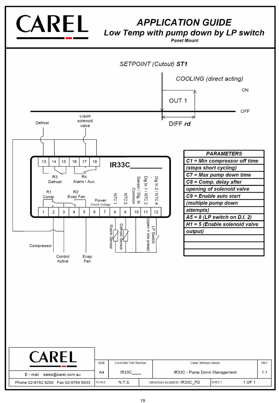
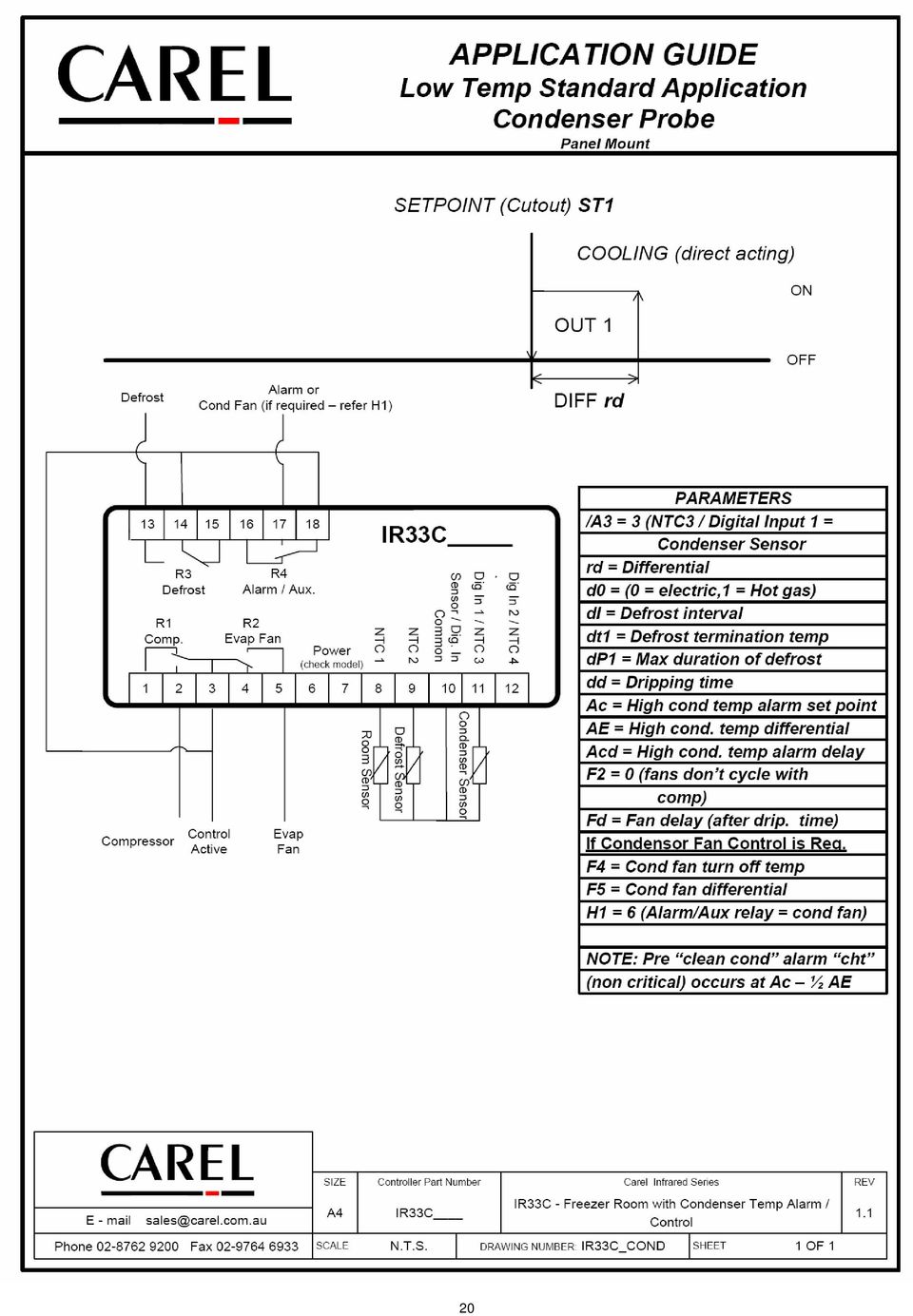
3 eatures and Benefits Based on IR32 Parameters Real Time lock ( RT ) Model Specific (defrost based on real time 7 day 24 hour) HAP (Hazard Analysis and ritical ontrol Point) Alarm Available on models with Real Time lock (RT) Models with RT can switch the aux output on and off based on a time program ompact Infrared Remote ALL MODELS! Digital inputs can be programmed to be sensors ondenser temperature alarm ( option to control condenser fan with Aux relay) Programg key (controller does not require power) ALL MODELS! 2 nd Evaporator control ( second evaporator sensor and defrost relay output option) Pump down management ( Solenoid valve (aux) output and LP switch input) Block level access for programg to simplify the movement between parameters 24V low temperature model New Mounting Bracket 3
 Pump down management ( Solenoid valve (aux) output and LP switch input) Block level access for programg to simplify")
4 4

5 5
6 IR33 Platform Technical tips IR33S / DN33S / MD33A are defaulted to enable off cycle defrost. To make the controller cooling only r3 must be equal to (H is now not used for this purpose). Any of the sensors can be programmed to be continually shown on the controllers LED display. If the temperature shown is not correct check that parameter /ti = or 2. Other options are 3=Probe 2, 4=Probe 3 etc. The temperature alarm can now be programmed to be relative or absolute. Default is relative (A = ) meaning if AH = +5 then the high alarm is Set point + 5 deg. If A = and AH = +5 then no matter what the set point I, the high alarm point is +5 deg. It is important to note that when saving parameter changes that the PRG key must now be pressed for approx 5 seconds (until the temperature comes onto the display). or existing IR32 users the main parameters have basically remained unchanged. Differential is still rd, defrost interval is still di etc. With the addition of the option to manage a second evaporator, dp (defrost duration) and dt (defrost terate temperature) have been replaced by dp, dp2 and dt, dt2 respectively. or normal operation the customer only needs to set dp and dt. (d_2 is only used when second evaporator management is enabled). Real time defrost and HAP functions are only available in models with Real Time lock. Models without RT will not permit the associated parameters to be adjusted. the cheat sheet we have highlighted in bold the main parameters that need adjusting for basic operation. or IR33 with only one sensor (no evaporator sensor), the alarm E (faulty evap sensor) is disabled by setting /A2 = (probe 2 not present). Parameter d does not disable this alarm. 6
 meaning if AH = +5 then the high alarm is Set point + 5 deg. If A = and AH = +5 then no matter what the set point I, the high alarm point is +5 deg.")
7 IR33 Platform Programg 7

8 IR33 Platform Parameters ode Block Parameter Model Unit Type Min. Max. Def. New /2 Pro Measurement stability MS 5 4 /3 Pro Probe display speed MS 5 /4 Pro Virtual probe (averaging on room & evap) = not active MS /5 Pro Select or ( = ) MS /6 Pro Decimal point ( = decimal point between 9.9 & +9.9) MS /ti Pro Sensor displayed on controller ( or 2 = ontrol sensor) MS 7 /te Pro Sensor shown on remote display MS 6 /P Pro Type of probe (=standard arel NT, =High Temp NT) MS 2 /A2 Pro Probe 2 configuration (eg 2=evap,3=cond, 4=low T cut out) MS 4 2 S 4 /A3 Pro Probe 3 configuration (eg = absent 2=evap,3=cond) MS 4 /A4 Pro Probe 4 configuration (eg =absent,2=evap,3=cond) MS 4 /A5 Pro Probe 5 configuration (eg =absent,2=evap,3=cond) S 4 /c Pro alibration of probe MS / 2 2. /c25 Pro alibration of probe 2345 / c2=probe 2, / c3=probe 3 MS / 2 2. St tl Temperature set point MS / r r2. rd tl ontroller differential S / rn tl Dead Zone (when used in Heat ool mode) S / 6 4 rr tl Reverse (heat) diff in dead zone control S /. 2 2 r tl Minimum Set Point allowed MS / 5 r2 5 r2 tl Maximum Set Point allowed MS / r 2 6 r3 tl Mode = cool with defrost, = cool only, 2 = heating S 2 r4 tl Value to increase Set Point by from Digital Input (see A4..) MS / r5 tl Enable temperature monitoring ( = yes) MS rt tl Temperature monitoring interval (display only parameter) MS hours 999 rh tl Max temperature recorded during period rt (display only) MS / rl tl Min temperature recorded during period rt (display only) MS / c np ompressor and fan start delay at power up S 5 c np Minimum time between 2 compressor starts S 5 c2 np Minimum compressor O time S 5 c3 np Minimum compressor ON time S 5 c4 np Duty setting (in case of control probe failure) S cc np Duration of continuous cycle (manual activation) S hours 5 c6 np Alarm bypass after continuous cycle S hours 5 2 c7 np Maximum PumpDown (PD) time S sec 9 c8 np ompressor start delay after opening Pump Down valve S sec 6 5 c9 np Enable autostart with Pump Down operation S c np Select PumpDown by time or pressure switch S c np Second compressor start delay S s 25 4 d Defrost type (= elec / temp term, = H.Gas / temp term S 4 2 = elec / time term, 3 = hot gas / time term 4 = pulse) di Interval between defrosts (if not using real time) S hours 25 8 dt End defrost temperature, (if d = or ) S / dt2 End defrost temperature, 2nd evaporator (if selected) S /
 MS /ti Pro Sensor displayed on controller ( or 2 = ontrol sensor) MS 7 /te Pro Sensor shown on remote display MS 6 /P Pro Type of probe (=standard arel NT, =High Temp NT) MS 2 /A2 Pro Probe 2")
9 ode Block Parameter Model Unit Type Min. Max. Def. New dp Maximum defrost duration S 25 3 dp2 Maximum defrost duration, 2 nd evap (if selected) S 25 3 d3 Delay starting defrost after stopping comp S 25 d4 Defrost at power up ( = no, = yes) S d5 Defrost delay at power up (if d4=) S 25 d6 Display during def.(=d (flash),=locked,2=) S 2 dd Dripping time after defrost S 5 2 d8 Bypass alarms after defrost S hours 5 d8d Alarm delay after door open from dig in S hours 25 d9 Defrost priority over compressor protection S d//d/2 Display defrost probe temp d/=def P,d/2=def P2) MS / d Time basis for defrost ( = hr/, = /sec) S d ompressor run time for demand defrost S hours 25 d ompressor run time temp set for demand defrost S / 2 2. d2 Advanced defrost enable S 3 dn Noal defrost duration (smart defrost) S 65 dh Proportional factor for variation in di (smart D) S 5 A Alarm and fan differential MS / A Type of alarm for AL and AH (=relative =absolute) MS AL Low alarm temp (see A for absol. or relative) MS / 5 2. AH High alarm temp (see A for absol. or relative) MS / 5 2. Ad Low and high temperature alarm delay MS 25 2 A4 onfiguration of digital input S 4 A5 onfiguration of digital input 2 MS 4 A6 Duty setting for comp from digital in alarm S A7 External alarm delay if using digital input S 25 A8 Enable alarms Ed and Ed2 (defrost end on time) S A9 onfiguration of digital input 3 S 4 Ado Door switch light management mode MS Ac High condenser temperature alarm set point S / AE High condenser temp. alarm differential S /. 2. Acd High condenser temp. alarm delay S 25 A Light sensor off time S s 25 AL Antifreeze alarm set point MS / Ad Antifreeze alarm delay MS 5 an an management (=according to 2,3,d 2 = room evap, 2 = evap temp ( A) an an start temperature / an ans cycle with comp ( = no, = yes) 3 an ans in defrost ( = on, = off) d an ans delay after dripping 5 4 an ondenser fan off temperature (on aux relay if enabled) MS / an ondenser fan differential MS / H n Serial address MS 27 9
,=locked,2=) S 2 dd Dripping time after defrost S 5 2 d8 Bypass alarms after defrost S hours 5 d8d Alarm delay after door open from dig in S hours 25 d9 Defrost priority over compressor")
10 ode Block Parameter Model Unit Type Min. Max. Def. New H n unction of relay 4 (,=alarm,2=aux,3=light,6=cond fan) MS 3 H2 n Keypad and IR locking MS 6 H3 n Remote control enabling code MS 255 H4 n Disable buzzer (=enabled, = disabled) MS H5 n unction of relay 5 Model specific (refer H) MS 3 H6 n Buttons to lock when keypad locked MS 255 H8 n Select output to activate with time band MS HPr n Print profile MS 5 H9 n Enable set point change with time MS Hdn n Number of default parameter sets MS 6 Hdh n Antisweat heater control offset MS / 5 2 HrL n Enable remote ind. of light status MS HrA n Enable remote ind. of aux status MS HsA n Enable alarms on network devices MS In n Standard control or master or slave MS 6 HAn/Hn HcP Number of events HA/H occurred MS 5 HA/H HcP Date/time of most recent HA/H MS y HcP Year years 99 M HcP Month months 2 d HcP Day days 7 h HcP Hour hours 23 n HcP Minute 59 t HcP Duration hours 99 Htd HcP HAP alarm delay MS 25 tdtd8 Defrost time band /8 S d Day days h Hour hours 23 n Minute 59 ton Light/aux ON time setting S d Day days h Hour hours 23 n Minute 59 tof Light/aux O time setting S d Day days h Hour hours 23 n Minute 59 tc RT date/time setting MS y Years years 99 M Month months 2 d Day of the month days 3 u Day of the week days h Hour hours 23 n Minute 59

11

12 2

13 3

14 4
15 5

16 6

17 7
18 8
19 9
20 2
21 2
22 22
23 23
24 24
25 25
26 26
27 27
28 IR33 Platform Alarm and Display descriptions ode Description Alarm Relay Buzzer Reset re ontrol probe fault E Probe fault E Probe 2 fault E2 Probe 3 fault E3 Probe 4 fault " " Probe not enabled LO Low temp alarm HI High temp alarm IA Digital input alarm (immediate) da Digital input alarm (delayed) Ed Defrost on evap ended by time /Man Ed2 Defrost on evap 2 ended by time /Man Pd Maximum pump down time /Man LP Low pressure alarm /Man AtS start in pump down /Man cht High condenser temp pre alarm /Man HT High condenser temp alarm Manual dor Door open alarm Etc Real time clock fault EE EPROM error (unit parameters) E EPROM error (operating parameters) HA HAP alarm "HA" H HAP alarm "H" ontroller in defrost ccb Start continuous cycle cce End continuous cycle db Start manual defrost de End manual defrost 28 IR33_Handout v2.3 5//8
Operating ambient temperature range: 5ºC to 50ºC Storage temperature range: -30ºC to 70ºC
 HOJA TÉCNICA 1400H101 Edición 01 (02 de 08) www.ako.es GENERAL TECHNICAL SPECIFICATIONS Temperature range: -50ºC to +99ºC type: NTC Total accuracy ( + controller): ±1ºC lead extension with cable AKO-15586:
THERMO KING TRUCK & TRAILER UNIT ALARM CODES THIS DOCUMENT SHOWS ALL CURRENT ALARM CODES FOR THERMO KING TRUCK AND TRAILER UNITS.
 THERMO KING TRUCK & TRAILER UNIT ALARM CODES THIS DOCUMENT SHOWS ALL CURRENT ALARM CODES FOR THERMO KING TRUCK AND TRAILER UNITS. NOT ALL CODES ARE POSSIBLE ON ANY INDIVIDUAL UNIT. IF THE ALARM APPLIES
INSTALLATION OPERATING & MAINTENANCE MANUAL
 INSTALLATION OPERATING & MAINTENANCE MANUAL Basic Climatic TM Controller Ecologic English November 2002 CONTENTS PAGE GENERAL DESCRIPTION 3 USER INTERFACE 4 The keypad incorporated on the unit 4 The keypad
T-100-R Installation Guide
 T-100-R Installation Guide Table of Contents Page 2 Overview T-100-R Z-Wave Thermostat 3-4 Installation HVAC System Setup 6 Installer Settings Menu Items 7-9 Installer Settings Summary 10-11 Wiring Standard
HVAC-32A. Operation Manual. Specifications. Digital Multistage Air Conditioning Controller with inbuilt Outside Air Economy function
 Specifications Supply Voltage 240VAC @ 0.07Amps or 24VAC @ 0.380Amps Relays 240V @ 12A max (resistive) / Comp1,2,3, Aux Ht, Rv O/B) Fuses (Equipment) 15 Amps Maximum 3AG Control Range Minus 10 to 50C Control
SERVICE MANUAL FOR 6535 SERIES TWO TON HIGH EFFICIENCY PACKAGED HEAT PUMPS
 SERVICE MANUAL FOR 6535 SERIES TWO TON HIGH EFFICIENCY PACKAGED HEAT PUMPS TABLE OF CONTENTS 1. Warnings...2 2. Accessibility Of Appliance...3 3. Unit Dimensions And Specifications...3 4. Unit Specifications
CONTENTS General features Front panel and buttons Installation List of the working parameters to be checked before starting the unit
 CONTENTS General features..... 1 Models available..... 1 Main features of the Infrared Series.... 2 Front panel and buttons..... 4 LED display Indicators..... 4 Keypad..... 5 Installation..... 6 Standard
Indoor coil is too warm in cooling mode or too cold in heating mode. Reversing valve or coil thermistor is faulty
 Codes Room Air Conditioner range: Indoor unit alarm s If timer lamp flashes for 1 second on, 1 second off, this indicates pre heating on the coil during heating mode and is not an error. If timer lamp
1 Introduction...3 2 General Description...3. 2.1 Functions... 3 2.2 Main Board... 3 2.3 Second compressor board... 4. 3 User Interface (Terminal)...
...") LCA - LCW - LCR Water chillers and heat pumps USER MANUAL GB INDICE 1 Introduction...3 2 General Description...3 2.1 Functions... 3 2.2 Main Board... 3 2.3 Second compressor board... 4 3 User Interface
LCA - LCW - LCR Water chillers and heat pumps USER MANUAL GB INDICE 1 Introduction...3 2 General Description...3 2.1 Functions... 3 2.2 Main Board... 3 2.3 Second compressor board... 4 3 User Interface
NL708 (XWA11V) Walk-In Temp / Door /Alarm / Light Module
 Walk-In Temp / Door /Alarm / Light Module") NL708 (XWA11V) Walk-In Temp / Door /Alarm / Light Module 1. General Description 1 2. General Warnings 1 3. Interface 2 4. Temp Alarms Setting 3 5. Programming 3 6. Light Management 4 7. Installation and
NL708 (XWA11V) Walk-In Temp / Door /Alarm / Light Module 1. General Description 1 2. General Warnings 1 3. Interface 2 4. Temp Alarms Setting 3 5. Programming 3 6. Light Management 4 7. Installation and
Application Engineering
 Application Engineering February 2011 Electronic Unit Controller Table of Contents 1. Introduction and Features... 2 1.1 Technical Specifi cations... 3 1.2 Pressure Probe Error Bypass... 3 1.3 Bump Start...
Install Guide 3M-50. Caution. Caution
 PG 1 Install Guide 3M-50 aution Your thermostat is a precise instrument, handle it with care. Turn off electricity to the HVA system before installing or servicing thermostat or any part of the system.
Controller for temperature control - EKC 102 REFRIGERATION AND AIR CONDITIONING. Manual
 Controller for temperature control - EKC 102 REFRIGERATION AND AIR CONDITIONING Manual Introduction Application The controller is used for temperature control refrigeration appliances and cold room Defrost
HEAT HEAT COOL HEAT PUMP COOL
 OWNER S MANUAL RESIDENTIAL THERMOSTAT P/N P374-1800 HEAT COOL HEAT PUMP Su AUTO 0I20: Pm 74 COOL HEAT 27 7-DAY MABLE DIGITAL THERMOSTAT 3 Configurable Outputs Accepts Optional Humidity Module: Control
User manual. Application program for pco 1, pco 2, pco 3. Standard Chiller Modular HP 1/4 Generic /Bitzer screw compressor and CAREL valve
 Standard Chiller Modular HP 1/4 Generic /Bitzer screw compressor and CAREL valve Application program for pco 1, pco 2, pco 3 User manual Manual Version: 1.4 dated 11/09/08 Program code: FLSTDmMSBE LEGGI
How To Set The Sensor On A Powerpoint 3.5 (Powerpoint) On A Blackberry 2.5A (Powerplant) On An Iphone Or Ipad (Powerplant) On The Blackberry 3.2 (
 On A Blackberry 2.5A (Powerplant) On An Iphone Or Ipad (Powerplant) On The Blackberry 3.2 (") VMBGPOD Touch panel with Oled display for VELBUS system 1 Binairy format: bits Description
VMBGPOD Touch panel with Oled display for VELBUS system 1 Binairy format: bits Description
SERVICE INSTRUCTION R410A. SPLIT TYPE ROOM AIR CONDITIONER Universal Floor / Ceiling Duct / Cassette Wall Mounted / Floor type INVERTER MULTI
 SERVICE INSTRUCTION SPLIT TYPE ROOM AIR CONDITIONER Universal Floor / Ceiling Duct / Cassette Wall Mounted / Floor type INVERTER MULTI R410A Models Indoor unit Outdoor unit AB*14LBAJ AB*18LBAJ AB*F14LAT
STERILIZERS, LABORATORY DRYING OVENS
 TS9026 TS9053 TS9135 TS9430 TS 9000 SERIES: STERILIZERS, LABORATORY DRYING OVENS Series TS9000 consists of four different cabinets available in sizes from 26 litres to 430 litres. Interior housing and
Standard 1/2 compressor chiller/heat pump
 Application program for pco Standard 1/2 compressor chiller/heat pump Manual version: 1.3-25/06/99 Program code: EPSTDEHP0A Rif.: 86EM Index Hardware architecture---------------------------------------------------------------------------------------------
CGC s Hybrid System Loop Control
 verview The CGC Group Hybrid Heat Pump System does NT operate with the same fluid loop temperatures as a conventional reversing Water Source Heat Pump system. The CGC system differs from a WSHP system
Regolatori per Refrigerazione Digitali FR... 1-2 canali
 Regolatori per Refrigerazione Digitali FR... 1-2 canali Manuale d Uso 1-2 Channel Regulators for Digital Refrigeration System Manuel Contents Safety warnings Page 20 Technical specifications Page 20 Description
Install Guide CT100. Caution. Caution ENGLISH. disconnect the power supply before beginning work.
 Install Guide CT100 PG 1 Caution top cover Your thermostat is a precise instrument, handle it with care. Turn off electricity to the system before installing or servicing thermostat or any part of the
SMM. Installation Operation Maintenance
 SMM Configuration SMM Module for Scroll Units, H Generation Installation Operation Maintenance 1 0 L80 IM 022 GB SMM Configuration SMM Module for Scroll Units, H generation Foreword These installation,
Aerona Air Source Heat Pumps
 ADDENDUM to INSTALLATION INSTRUCTIONS for Aerona Air Source Heat Pumps DOC.87-05/05 Rev.04 March 2013 ATTENTION INSTALLERS - UPDATED INFORMATION! Your Grant Aerona Air Source Heat Pump has a number of
RESIDENTIAL THERMOSTATS CLIMATEMASTER
 ESIDENTIAL THEMSTATS LIMATEMASTE ETHEMAL HEATIN AND LIN MFT SYSTEMS ESIDENTIAL THEMSTAT PDUT UIDE THE LBAL LEADE esidential Thermostats 3.30 in [83.8mm] Fan: turns continuous fan FF or N 0.8 in Depth
SERVICE INSTRUCTION R410A. WALL MOUNTEDtype INVERTER SPLIT TYPE ROOM AIR CONDITIONER. Models Indoor unit Outdoor unit
 SERVICE INSTRUCTION SPLIT TYPE ROOM AIR CONDITIONER WALL MOUNTEDtype INVERTER Models Indoor unit Outdoor unit ASYG07LECA ASYG09LECA ASYG12LECA ASYG14LECA AOYG07LEC AOYG09LEC AOYG12LEC AOYG14LEC R410A CONTENTS
3. AIR CONDITIONER CONTROLLER (UNIT)
") 9 3. AIR CONDITIONER CONTROLLER (UNIT) Functions of Full Automatic Air Conditioner ler 1 1. Temp SW 2. Auto SW 3. OFF SW 4. Amb SW 5. Mode SW 6. Blower SW 2 3 10 5 8 7 9 Temperature control: Air mix actuator
9 3. AIR CONDITIONER CONTROLLER (UNIT) Functions of Full Automatic Air Conditioner ler 1 1. Temp SW 2. Auto SW 3. OFF SW 4. Amb SW 5. Mode SW 6. Blower SW 2 3 10 5 8 7 9 Temperature control: Air mix actuator
Programmable Thermostat MODEL 3312026.XXX With Dehumidify 3312024.XXX With Out Dehumidify
 Comfort Control Center 2 Thermostat Operating Instructions Programmable Thermostat MODEL 3312026.XXX With Dehumidify 3312024.XXX With Out Dehumidify TABLE OF CONTENTS About your new thermostat Features...2
Dyeing Programmer DP - 01
 Dyeing Programmer DP - 01 Display and Controls. 1) Display: 16/2 alphanumeric display 2) Temperature range: 0 to 150 degree. 3) Resolution: 1 degree. 4) Accuracy: +/- 1 degree. 5) Temperature control setting:
Gastronorm Supra Cabinet & Counter
 By Appointment to Gastronorm Supra Cabinet & Counter Her Majesty Queen Elizabeth II Suppliers of Commercial Refrigeration Foster Refrigerator (UK) Ltd King s Lynn S e r v i c e M a n u a l Gastronorm Supra
RZAHUC program version 1.1 Regulation for Reznor Air Handling Units
 INSTALLATION INSTRUCTIONS OPTION 1xxx 1104_1000_EN Comfort Regulation (Carel pco) Detailed instructions RZAHUC program version 1.1 Regulation for Reznor Air Handling Units INDEX 1. Introduction... 4 1.1.
Dixell. Electronic Controls Handbook September 2000. Programming Flow Charts & Parameter Lists for:
 Dixell Electronic Controls Handbook September 2000 Programming Flow Charts & Parameter Lists for: XR100 Series - Refrigeration Controller XT Series - Heating & Cooling Controllers XC Series - Step Controllers
Porcia, 20 novembre 2012
 1 2 PLZ RANGE 14-18-20 3 TECHNICAL NUMBERS 4 MAIN COMPONENTS CONTROL SAFETY HYDRONIC OUTLET WATER TEMPERATURE INLET WATER TEMPERATURE AIR OR WATER EXTERNAL TEMPERATURE FRESH AIR WITH PRESSURE DIFFERENTIAL
USER MANUAL WARNING! CONTENTS MODEL 1 SPECIFICATIONS READ ALL INSTRUCTIONS BEFORE PROCEEDING. Non-Programmable Single Stage Heat/Cool Thermostat
 Builder MODEL 1010 Series Non-Programmable Single Stage Heat/Cool Thermostat USER MANUAL Compatible with low voltage single stage gas, oil or electric heating or cooling systems, including single stage
COMPTROL 5000 INDEX 52. Issue 5.99 AIR CONDITIONING MICROPROCESSOR OPERATING INSTRUCTIONS. STULZ GmbH, Hamburg
 COMPTROL 5000 INDEX 52 Issue 5.99 AIR CONDITIONING MICROPROCESSOR STULZ GmbH, Hamburg OPERATING INSTRUCTIONS Contents Page INTRODUCTION... 4 NOTES ON SAFETY... 4 PAGE CODE... 4 DESCRIPTION OF THE CONTROLLER...
National Grid Small Business Energy Efficiency Program Overview. Central New York Energy Expo March 30, 2010
 National Grid Small Business Energy Efficiency Program Overview Central New York Energy Expo March 30, 2010 Agenda National Grid Cooler Retrofit Program Refrigeration 101 Smart Thermostat Controls, Anti-Sweat
its ELECTRIC POSITION for electric heat, or set the units fan control appropriately to ELECTRIC or another appropriate setting.
 Troubleshooting Poor Temperature Regulation This page lists problems that may affect the temperature performance of your LUX thermostat with suggested resolutions. For more detailed information please
INSTALLATION MANUAL. Address card EKAC10B
 INSTALLATION MANUAL 88 44 µchiller compact 70 64 4a 4b G G0 power supply G G0 power supply 50 5 50 5 4a 4b 5a 5b 4 5a 5b Installation manual READ THIS MANUAL ATTENTIVELY BEFORE STARTING UP THE UNIT. DO
Digital controller with alarm management XR40CX
 1. CONTENTSGENERAL WARNING Digital controller with alarm management XR40CX 1.1 PLEASE READ BEFORE USING THIS MANUAL This manual is part of the product and should be kept near the instrument for easy and
SERVICE INSTRUCTION R410A. WALL MOUNTEDtype SPLIT TYPE ROOM AIR CONDITIONER INVERTER. Models Indoor unit Outdoor unit AOU 9RLFW AOU12RLFW AOU15RLS
 SERVICE INSTRUCTION SPLIT TYPE ROOM AIR CONDITIONER WALL MOUNTEDtype INVERTER Models Indoor unit Outdoor unit ASU 9RLF ASURLF ASU5RLS AOU 9RLFW AOURLFW AOU5RLS R40A CONTENTS. DESCRIPTION OF EACH CONTROL
USER S MANUAL HSC-24A
 AIRREX AIR CONDITIONER USER S MANUAL HSC-24A Thank you for purchasing an AIRREX AIR CONDITIONER. BEFORE operation please read this user s manual carefully. Keep this manual readily available. It is ESSENTIAL
TICS - Integrated Control Strategy TICS - Total Integrated Control Strategy Mid Range System
 TICS - Total Integrated Control Strategy Mid Range System Underfloor Heating & Cooling Control Solutions Energy efficient Heating and cooling TICS - Mid Range System Mid Range System TICS Mid Range Install
REMOTE CONTROL MANUAL
 REMOTE CONTROL MANUAL ENGLISH CONTENT PRECAUTIONS...1-2 USING THE REMOTE CONTROL UNIT...3 OPERATION...4-9 Thank you for purchasing our Room Air Conditioner. Before using your air-conditioner, please read
USER MANUAL EXTROLLER
 COAIRE SCREW AIR COMPRESSORS USER MANUAL EXTROLLER SERIAL NO. : MODEL NO. : CAUTION For proper and safe use of the compressor, please follow all instructions and safety precautions as identified in this
MP-4000 Alarm List (Software version 2.4.3 or later)
") Service Bulletin SUBJECT: MP4000 Alarm s BULLETIN: C 100 DATE: June 19, 2013 ALARM LIST Where it is possible the alarm number is kept the same as for MP-3000. MP-3000 holds alarm number from 0 to 127.
Service Bulletin SUBJECT: MP4000 Alarm s BULLETIN: C 100 DATE: June 19, 2013 ALARM LIST Where it is possible the alarm number is kept the same as for MP-3000. MP-3000 holds alarm number from 0 to 127.
TABLE 1: Wiring Terminals. Connect to... 1C 1H 2C 2H 1H1C 2H1C 2H2C 3H2C
 Installation TURN OFF POWER TO THE SYSTEM AT THE MAIN POWER PANEL TO AVOID ELECTRICAL SHOCK. Installation should be carried out by an electrician or a qualified technician. 1.1 Find a Location for the
Cat Electronic Technician 2015A v1.0 Product Status Report 4/20/2016 2:49 PM
 Page 1 of 19 Cat Electronic Technician 2015A v1.0 Product Status Report 2:49 PM Product Status Report Parameter Value Product ID WRK00337 Equipment ID WRK00337 Comments A01-52 C9 330D (THX37891) Parameter
CONTENTS 1. IMPORTANT NOTICE 2 2. TECHNICAL SPECIFICATION 3 3. OPERATION DETAILS 4 4. ELECTRICAL SCHEMATIC DIAGRAM 13 5. EXPLOSION VIEW 16 6
 TCL WALL MOUNTED SPLIT-TYPE AIR CONDITIONERS SERVICE MANUAL No.TE080528 Models KFTHP-12 KFTHP-18 KFTHP-24 CONTENTS 1. IMPORTANT NOTICE 2 2. TECHNICAL SPECIFICATION 3 3. OPERATION DETAILS 4 4. ELECTRICAL
SECTION 15750 PACKAGED ROOFTOP AIR CONDITIONING UNITS
 SECTION 15750 PART 1 - GENERAL 1.01 DESCRIPTION A. Section includes requirements for roof mounted, self-contained units, with electric cooling, and electric or reverse refrigeration cycle (heat pump) heating
R22. K Control. Indoor Unit. Nomenclature. Compatibility PL H 3 G K H B. Unit style Heat Pump Horse Power
 R22. K Control. Indoor Unit. Nomenclature. PL H 3 G K H B Compatibility Unit style Heat Pump Horse Power Control Boost Heaters R22. K Control. Outdoor Unit. Nomenclature. PU H 3 Y K A Compatibility Outdoor
Single Zone LCD Thermostat Operating Instructions
 Fan Cool Furnace *Heat Pump or Heat Strip On/Off F Single Zone LCD Thermostat Operating Instructions MODEL 3313192.XXX Cool/Furnace 3313193.XXX Cool/Furnace/Heat Pump 3313194.XXX Cool/Furnace/Heat Strip
Water Fired Chiller/Chiller-Heater. WFC-S Series: 10, 20 and 30 RT Cooling
 Water Fired Chiller/Chiller-Heater WFC-S Series: 1, 2 and 3 RT Cooling W E A R E F R I E N D L Y T O T H E E A R T H Water Fired SINGLE-EFFECT Chiller or Chiller-Heater Absorption Principle Cooling Cycle
Vertical Display and Storage B1350-2. SKOPE Gen2: Three Door Chiller
 Vertical Display and Storage User Manual MAN1227 Rev. 3.0 March 2008 edition CONTACT ADDRESSES Designed and Manufactured by New Zealand SKOPE INDUSTRIES LIMITED PO Box 1091, Christchurch New Zealand Freephone:
How To Set Up A Furnace Pump
 ork etail System Specific iring Diagrams January 2012 Using Honeywell hermostats Index for Low Voltage iring Affinity Units utdoor Indoor System Description Page ZH 2 Stage HP AV or MV Variable Speed Air
PID Microprocessor temperature controllers CTD43 - CTD46 - CTH46
 PID Microprocessor temperature controllers CTD43 - CTD46 - CTH46 Display 1. Red measurement display (or the set point for CTD 43 by pressing, indicated by a flashing decimal point). 2. Green display of
New Deluxe Wall Mounted Heat Pump Series EXTERIOS
 New Deluxe Wall Mounted Heat Pump Series EXTERIOS May 2013 New Deluxe Wall Mounted Heat Pump Series Panasonic Adding New Air Conditioner Lineup Setting Another Mile Stone in the US Ductless Split History
Standard 1/3 compressor pack control Manual version: 1.0-21/10/94
 Application program for pco Standard 1/3 compressor pack control Manual version: 1.0-21/10/94 Program code: EPSTDEFC2A Rif.: 83EM pco controller for refrigeration EPSTDIFC2A ver. 1.002 (normally closed
SWIMMING POOL HEAT PUMP Owners Manual
 SWIMMING POOL HEAT PUMP Owners Manual This manual refers to the 17.0kw and 21.0kw models only. The heat pump unit is sold with a 1 year warranty. In addition there is a 2 year parts warranty on the compressor
Install Guide CT101. Caution. Caution
 Install Guide CT101 PG 1 Caution top cover Your thermostat is a precise instrument, handle it with care. Turn off electricity to the system before installing or servicing thermostat or any part of the
Variable Air Volume - VAV
 Mode Enable Sensor Options Variable Air Volume - VAV The temperature of this sensor will determine if the unit is in heating, cooling or vent mode during occupied operation. The following options are available:
Development of CO 2 A/C System
 Development of CO 2 A/C System CK s s Aiming of CO 2 Air Conditioning System Aiming CK develops two kinds of CO 2 air conditioning systems. These are the one for the vehicles of a source of the present
Safety & Installation Instructions
 Home omfort ontrol Model 8910 READ AND SAVE THESE INSTRUTIS Safety & Installation Instructions Table of contents Installation Thermostat installation location recommendations.. 2 Thermostat mounting...
PROCEDURES FOR SELF DIAGNOSTICS
 PROCEDURES FOR SELF DIAGNOSTICS Baum Tools Unlimited Inc. March 31, 1999 TAU 2.1 READING ACTUAL VALUES 1. Remove the operating console from the TAU 2. At the upper side of the operating consol there is
Technical Support Bulletin Nr. 11 Alarms Codes
 Technical Support Bulletin Nr. 11 Alarms Codes Contents! Introduction! Alarm Tables Index! Alarm Tables Introduction This document describes all the error messages that display on devices for commercial
HEAT PUMP PROGRAMMABLE THERMOSTAT
 HEAT PUMP PROGRAMMABLE THERMOSTAT SA PM 3 COOL TEMP Form 44014-01 r010408 Model 43168 Owners Manual 1 Congratulations! Heat Pump Programmable Thermostat Model 43168 THERMOSTAT CONTROLS Switches & Buttons...15
Sensi TM. Wi-Fi Programmable Thermostat MANUAL OPERATION. Version: March 2016 2016 Emerson Electric Co. All rights reserved.
 Sensi TM Wi-Fi Programmable Thermostat MANUAL OPERATION Version: March 2016 2016 Emerson Electric Co. All rights reserved. Contents MANUAL OPERATION GUIDE Buttons and Icons 3 Basic Functionality 4 Manual
C-Bus Application Messages & Behaviour Chapter 25 Air Conditioning
 C-Bus Application Messages & Behaviour Chapter 25 Air Conditioning Document Number: CBUS-APP/25 Comments on this document should be addressed to: Engineering Manager Clipsal Integrated Systems PO Box 103
F453. TiF453. User guide 10/11-01 PC
 F453 TiF453 User guide 10/11-01 PC 2 TiF453 User guide Contents 1. Hardware and Software requirements 4 2. Installation 4 1.1 Minimum Hardware requirements 4 1.2 Minimum Software requirements 4 3. Fundamental
INSTALLATION AND OPERATION MANUAL
 RCS MODEL ZC4 4 ZONE HVAC INSTALLATION AND OPERATION MANUAL DCN: 141-0020-02 /0/03 INTRODUCTION The 4 Zone HVAC Controller series allows up to 4 standard electronic thermostats to independently control
ELECTRIC POSITION for electric heat, then confirm with Fan Test below.
 Troubleshooting Poor Temperature Regulation This page lists problems that may affect the temperature performance of your LUX thermostat with suggested resolutions. For more detailed information please
W3000 TECHNICAL MANUAL C0240111-06-07-GB
 H W3000 TECHNICAL MANUAL C0240111-06-07-GB For software versions CA15 Replaces C0240111-01-07-GB G B CLIMAVENETA S.p.A Via Sarson, 57C 36061 Bassano del Grappa(VI)-ITALY Tel. (+39) 0424 509 500 Fax. (+39)
Automatic start of a generator
 Automatic start of a generator General description This application note will help you to set your Xtender for an automatic start of a generator as per different parameters such as the output power, the
Chilled Water System Commissioning: Variable Primary Flow. John D. Villani, P.E. Associate Grumman/Butkus Associates
 Chilled Water System Commissioning: Variable Primary Flow John D. Villani, P.E. Associate Grumman/Butkus Associates AIA Quality Assurance Learning Objectives 1. History of chilled water system configurations
CCH/CCW, VFC/VFW, MHC/MHW, LVC/LVW
 Operation & Maintenance Manual OM 931-6 Group: WSHP Part Number: 910157590 Date: September 2014 MicroTech III Unit Controller for Water Source Heat Pump Units Used with Enfinity Models CCH/CCW, VFC/VFW,
Alpha Climatic Programmable Modulating Boiler Energy Manager. Installation and User Instructions
 Alpha Climatic Programmable Modulating Boiler Energy Manager Part No 3.022144 (Hard Wired) Part No 3.022143 (Radio Frequency) Installation and User Instructions 1. Description The Alpha Climatic energy
Modbus Register Map: Environmental Management System and Environmental Monitoring Unit 990-0589A 02/2005
 // Version 102 //Absolute Starting Register Number, (Hexadecimal) Modbus Register Map: Environmental Management System and Environmental Monitoring Unit 990-0589A 02/2005 Absolute Starting Register Number,
Conventional Fire Detection and Extinguishant Control System Specification
 Conventional Fire Detection and Extinguishant Control System Specification Page 1 of 9 Scope Furnish a complete 24VDC Conventional, electrically supervised, combined fire detection and extinguishant release
Using the STC-1000+ firmware
 Using the STC-1000+ firmware Project home at Github Features Both Fahrenheit and Celsius versions Up to 6 profiles with up to 10 setpoints. Each setpoint can be held for 1 999 hours (i.e. up to ~41 days).
IC100CX. dixel. ichill 100CX. Quick reference guide. 1592022550 Quick reference guide IC100CX GB rel.1.0 03/03/2008 Page 1 di 39
 IC1CX dixel ichill 1CX Quick reference guide 15922255 Quick reference guide IC1CX GB rel.1. 3/3/28 Page 1 di 39 IC1CX INDEX 1. General Advices 2 2. User Interface 3 3. Remote Keyboard VICX61 4 4. Display
sip Sanyo Modbus Guide Technical Specification Pinouts, Cable Connections & Wiring Issue 2: February 2009 Synapsys Solutions Ltd, all rights reserved
 Sanyo Section : Section : Section : Section : Section : sip Modbus Guide Configuration Modbus Table Technical Specification Pinouts, Cable Connections & Wiring Alarm Fault Codes Issue : February 009 Section
Electrical Systems - IQAN Digital Control System. IQAN Control System Components... 5.1.3
 Section 5.1 Electrical Systems - IQAN Digital Control System IQAN Control System Components........................... 5.1.3 IQAN Operational Description: At Machine Startup.....................................
Thermostat with display
 H/LN4691-0 674 59-64170 Thermostat with display RA00118AA_I-01PC-13W39 www.homesystems-legrandgroup.com Thermostat with display Contents Thermostat with display 1 Introduction 4 1.1 Warnings and recommendations
Technical Support Bulletin Nr. 20 Special AC Functions
 Technical Support Bulletin Nr. 20 Special AC Functions Summary! Introduction! Hot Start Control! Adaptive Control! Defrost Start Temperature Compensation Control! Anti-Sticking Control! Water Free Cooling
Water Priming Mode Purge air from plumbing system. How do I solve ER-3 WATER PRIME: TIPS ON FILLING SPA IMPORTANT NOTE WARNING
 Water Priming Mode Purge air from plumbing system TIPS ON FILLING SPA Before filling remove spa skirt and be sure that all valves in the plumbing system are fully open to maximise the amount of air that
QUICK INSTALLATION GUIDE
 QUICK INSTALLATION GUIDE Read Installer Notes before removing cover from Thermostat. 1F85RF-275 Wireless Remote Kit INSTALLER NOTES IMPORTANT Do not apply power to the thermostat or wireless sensor until
HP 5 Microprocessor Control for Mammoth Water Source Heat Pumps
 HP 5 Microprocessor Control for Mammoth Water Source Heat Pumps Operation and Maintenance Manual Model: 71028004 Applies to: Single Circuit Water-to-Water Twin Circuit Units Without DDC Controls MAMM WHSP
Installation Guide. LR-HWLV-HVAC TouchPRO Wireless. System Types
 Installation Guide LR-HWLV-HVAC TouchPRO Wireless Touchscreen Thermostat System Types Gas, oil, or electric heat with air conditioning Warm air, hot water, high efficiency furnaces, heat pumps, steam,
Alerts and Delta T Diagnostics with the Prestige 2.0 IAQ Thermostat
 Alerts and Delta T Diagnostics with the Prestige 2.0 IAQ Thermostat MOUNTING LOCATIONS Refer to the guidelines below and Fig. 1 5 for mounting locations of the Discharge and Return Air Temperature Sensors.
MicroTech III Unit Controller for Water Source Heat Pump Units
 Operation & Maintenance Data OM 931-3 Group: WSHP Part Number: 669479403 Date: May 2012 MicroTech III Unit Controller for Water Source Heat Pump Units 2012 McQuay International 800.432.1342 www.daikinmcquay.com
PANASONIC TROUBLE SHOOTING GUIDE
 A General Guide To Room Style Products Pipework Pipe sizes and lengths should be as the relevant Technical Guide Both lines should be insulated No line accessories or oil traps should be fitted In cooling
MicroTech III Unit Controller for Water Source Heat Pump Units
 Operation & Maintenance Data OM 931-1 Group: WSHP Part Number: 910100893 Date: April 2009 MicroTech III Unit Controller for Water Source Heat Pump Units 2009 McQuay International Table of Contents Introduction...
Model: AC-S13CG x 2. Model No: AC-S13CGx2.doc Version 1.0
 Air Conditioner Service Manual 2 3 Model: AC-S13CG x 2 3 Content Technical specification.. 4 Performance curve.5 Outline & dimension of indoor unit..10 Outline & dimension of outdoor unit 11 Exploded view
HCE80/HCC80/HCE80R/HCC80R
 HCE80/HCC80/HCE80R/HCC80R UNDERFLOOR HEATING-ZONEING CONTROLLERS PRODUCT DATA FEATURES Easy and fast installation because the new wiring design Pluggable terminals for fast wiring connection because clamp
HVAC SYSTEM (AUTO A/C) (DIAGNOSTICS) AC
 (DIAGNOSTICS) AC") HVAC SYSTEM (AUTO A/C) (DIAGNOSTICS) AC Page. Basic Diagnostic Procedure.... General Description...3 3. Electrical Components Location...6 4. A/C Control Module I/O Signal...8 5. Self-diagnosis...0 6.
HVAC SYSTEM (AUTO A/C) (DIAGNOSTICS) AC Page. Basic Diagnostic Procedure.... General Description...3 3. Electrical Components Location...6 4. A/C Control Module I/O Signal...8 5. Self-diagnosis...0 6.
AC-115 Compact Networked Single Door Controller. Installation and User Manual
 AC-115 Compact Networked Single Controller Installation and User Manual December 2007 Table of Contents Table of Contents 1. Introduction...5 1.1 Key Features... 6 1.2 Technical Specifications... 7 2.
Air Conditioning System
 Air Conditioning System 1 Chonan Technical Service Training Center Chonan Technical Service Training Center 2 Objectives To understand the components of air conditioning system. To understand the control
Dealer Sales & Service Guide
 Analog Models w/thermostat or Timerstat Heat Siphon Not Starting 1 BREAKER TRIPPED - Check Breaker Box for correct size breaker Breakers: EX; Domestic model 2.25hp (20amp) 3.25hp (40amp) 5hp (50amp) check
Thermostatic Wiring Principles by Bob Scaringe Ph.D., P.E.
 Thermostatic Wiring Principles by Bob Scaringe Ph.D., P.E. Basic Thermostat Types Many technicians have great difficulty understanding how to properly wire a thermostat or how to replace a thermostat with
Operation manual. Daikin Altherma low temperature monobloc EBLQ05CAV3 EBLQ07CAV3 EDLQ05CAV3 EDLQ07CAV3
 EBLQ05CAV3 EBLQ07CAV3 EDLQ05CAV3 EDLQ07CAV3 English Table of Contents Table of Contents 1 About this document 2 2 About the system 2 2.1 Components in a typical system layout... 2 3 Operation 3 3.1 Overview: