NL708 (XWA11V) Walk-In Temp / Door /Alarm / Light Module
|
|
|
- Lenard Thomas
- 9 years ago
- Views:
Transcription
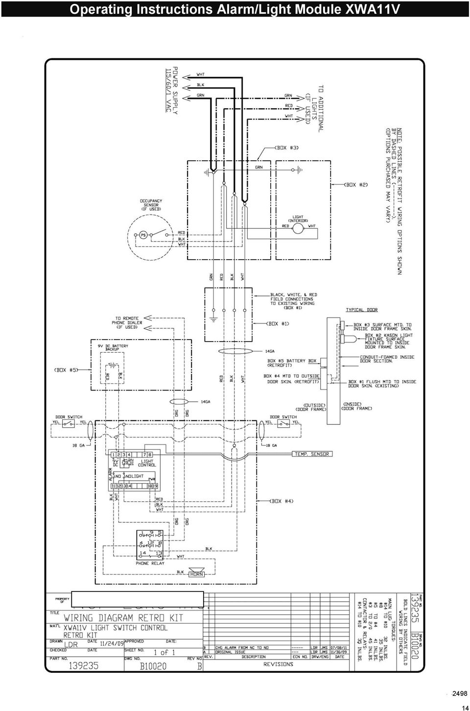
1 NL708 (XWA11V) Walk-In Temp / Door /Alarm / Light Module 1. General Description 1 2. General Warnings 1 3. Interface 2 4. Temp Alarms Setting 3 5. Programming 3 6. Light Management 4 7. Installation and Mounting 4 8. Electrical Connections 4 9. Use of the Programming Hot Key Alarm Signals Technical Data Connections Parameter Map Parameter List 8 Quick Sheet 9 Parts Lists 10 Dwg. No. A32907 Light Manager with Options 11 Dwg. No. B10007 Wiring Diagram Light Manager with Options 12 Dwg. No. A32942 Light Manager Retrofit Kit 13 Dwg. No. B10020 Wiring Diagram Retro Kit 14 Occupancy Sensor for Light Operation Settings 15 Remote Buzzer Installation 17

2 XWA11V Walk-In Temp / Door /Alarm / Light Module 1. GENERAL DESCRIPTION Model XWA11V, 100x64 mm format, is a microprocessor-based controller, suitable for temperature monitoring and alarming in a walk-in cooler or freezer. It is provided with two (2) Relay Contacts to control lights and an external alarm. It is provided with one (1) NTC probe input for temperature measurement. The unit has 2 Digital Inputs, one for a Door Switch and the 2nd as an optional Panic Switch. See the catalog for optional accessories. One 5Pin Input allows the user to program the parameter list with a Hot Key (see section 9) Note: The default settings are listed in the back of this manual. They are set for Coolers (Medium Temp). For Freezers (Low Temp) you MUST Change the ALL and ALU settings. See Section GENERAL WARNINGS 2.1 PLEASE READ BEFORE USING THIS MANUAL This manual is part of the product and should be kept close to the instrument for easy and quick reference. The instrument shall not be used for purposes different from those described hereunder. It cannot be used as a safety device. Check the application limits before proceeding. Note: If equipped with a battery backup, the battery must be installed after the walk-in has reached its operating temperature. 2.2 SAFETY PRECAUTIONS Check if the supply voltage is correct before connecting the instrument. Do not expose the back of the instrument to water or moisture: use the controller only within the operating limits avoiding sudden temperature changes with high atmospheric humidity to prevent the formation of condensation. Warning: disconnect all electrical connections before performing any maintenance operation. Fit the probe where it is not damaged by the end-user. The instrument must not be opened. In case of failure or faulty operation send the instrument back to the distributor (see address) with a detailed description of the fault. Consider the maximum current that can be applied to each relay (see Technical Data). Ensure that the wires for probes, loads and the power supply are separated and far enough from each other, without crossing or intertwining, or you may get bad temperature readings. Be sure to seal any J-box with RT sealant to prevent cold and moisture intrusion. 1


 when an ALARM is happening. Hot key programming: with the instrument on, insert the hot key and then press the UP button.")
3 3. INTERFACE Operating Instructions Alarm/Light Module XWA11V 3.1 KEY FRONT PANEL OPERATION In Programming Mode press to select a parameter or to confirm an operation. Press and hold this key for more than 5 s to turn the controller OFF. Press and hold this key for more than 1 s to turn the controller back ON. Press to see the HIGH Temp ALARM (ALU parameter) Press to see the LOW Temp ALARM (ALL parameter) In Programming Mode press to browse parameter codes. Press to increase the displayed value. Press to mute the buzzer (+ relay) when an ALARM is happening. Hot key programming: with the instrument on, insert the hot key and then press the UP button. In Programming Mode press to browse parameter codes. Press to decreases the displayed value. Switch ON and OFF the light of the cold room KEY COMBINATIONS: PRESS SIMULTANEOUSLY To lock and unlock the Keyboard. To enter the Programming Mode. To exit the Programming Mode. To enter a new value for the HIGH Temp ALARM (ALU). To enter a new value for the LOW Temp ALARM (ALL). 3.2 USE OF LEDS Each LED function is described in the following table: 2
 when an ALARM is happening. Hot key programming: with the instrument on, insert the hot key and then press the UP button.")
4 4. TEMP ALARM SETTINGS 4. TEMP ALARMS SETTING 4.1 HOW TO SET THE MIN TEMPERATURE ALARM To modify the minimum (LOW) Temp ALARM: hold the minimum Temp alarm is displayed. Change the value using the UP and DOWN keys. Press the SET key to confirm the new value and exit. keys pressed for 3 s until the 4.2 HOW TO SET THE MAX TEMPERATURE ALARM To modify the max (HIGH) Temp ALARM: hold the alarm is displayed. Change the value using the UP and DOWN keys. Press the SET key to confirm the new value and exit. keys pressed for 3 s until the max Temp 5. PROGRAMMING 5.1 HOW TO CHANGE A PARAMETER VALUE MAIN MENU 1. Enter the Programming Mode by pressing the SET and DOWN key for 3s ( and will start blinking). 2. Select the required parameter. By using the UP or DOWN KEY 3. Press the SET key to display its value (now only the LED is blinking). 4. Use UP or DOWN to change its value. Press SET to store the new value and move to the following parameter. To exit: Press SET + UP or wait 15 s without pressing a key. NOTE: the set value is stored even when the procedure is exited, by waiting the time-out to expire. 5.2 THE HIDDEN MENU (PR2) The hidden menu includes all the parameters of the instrument HOW TO ENTER THE HIDDEN MENU (PR2) 1. Enter the Programming Mode by pressing the Set + down key for 3s ( and starts blinking). 2. When a parameter is displayed, release and re-press the SET + down for more than 7s. 3. The Pr2 label will be displayed immediately followed from the HY parameter. NOW YOU ARE IN THE HIDDEN MENU. 4. Select the required parameter as above 5. Press the SET key to display its value (Now only the LED is blinking). 6. Use UP or down to change its value. 7. Press SET to store the new value and move to the following parameter. To exit: Press SET + up or wait 15s without pressing a key. NOTE: the set value is stored even when the procedure is exited by waiting the time-out to expire HOW TO MOVE A PARAMETER FROM THE HIDDEN MENU TO THE FIRST LEVEL AND VICEVERSA Each parameter present in the HIDDEN MENU can be removed or put into THE FIRST LEVEL (user level) by pressing SET + down. In HIDDEN MENU when a parameter is present in First Level the decimal point LED is on. 5.3 HOW TO LOCK THE KEYBOARD 1. Keep pressed for more than 3s the UP and DOWN keys. 2. The POF message will be displayed and the keyboard will be locked. At this point it will be possible only to see the Set Point or the MAX or MIN Temp stored 3. If a key is pressed more than 3s the POF message will be displayed. 3

5 5.4 TO UNLOCK THE KEYBOARD Keep pressed together for more than 3s the UP and DOWN keys. The PON message is displayed 6. LIGHT MANAGEMENT 6.1 TIMED REGULATION: I1L = Y With i1l = y the light remains on at least for the LHt parameter. The LHt timer is re-initialized every time the light button is pushed. With LHt=0 the light remains on until the light button is pushed again. The light is switched on every time one of the following conditions happens: the door is open (i1f = dor) the presence sensor is activated (i2f = LHt) the light button is pushed The light is switched off when all the following conditions happen: the LHt timer is exhausted the door is closed (i1f = dor) the presence sensor is de-activated (i2f = LHt) Light button regulation: i1l = n The lights will flash (for 2 minutes) every 20 seconds for the FLH time (0-5 min) at the end of the LHt time as a warning that the lights are about to turn off (for incandescent and LED lights only). The light button has a higher priority than digital inputs therefore: - if the light was switched on by button the digital input can not modify its status. - if the light was switched on by digital input, the light button can modify its status. 7. INSTALLATION AND MOUNTING 7.1 MOUNTING OF XWA11V PR10000 The XWA11V must be mounted on vertical panel, in a J-Box (Steel City PN /2) or equal or wall mounted using an appropriate enclosure. The Ambient Temp range for correct operation is F (0-55 C). Avoid installation in places subject to strong vibrations, corrosive gases, excessive dirt or humidity. The same recommendations apply to probes. 8. ELECTRICAL CONNECTIONS The instrument is provided with ¼ fast-on terminal blocks to connect cables with a cross section up to.110 for the digital and analog inputs. Relays and power supply have a Fast-on connection (.250 ). For supply connections, use 14 AWG or larger copper or CU wire only rated at least 90 C (194 F). Before connecting cables make sure the power supply complies with the instrument requirements. Separate the probe cables from the power supply cables, from the outputs and the power connections. Do not exceed the maximum current allowed on each relay and in case of heavier loads use a suitable external relay. N.B. Maximum current allowed for all the loads is 15A. 8.1 PROBE CONNECTIONS The probe shall be mounted with the bulb upwards to prevent damages due to casual liquid infiltration. It is recommended to place the thermostat probe away from air streams to correctly measure the average room temperature. The probe can be extended up to 300 ft. Check calibration when running long lengths over 100ft. 4
 the presence sensor is activated (i2f = LHt) the light button is pushed The light is switched")
6 9. USE OF THE PROGRAMMING HOT KEY 9.1 HOW TO PROGRAM A HOT KEY FROM THE INSTRUMENT (UPLOAD) 1. Program one controller with the front keypad. 2. When the controller is ON, insert the Hot key and push UP key; the "upl" message appears followed a by flashing End 3. Push SET key and the End will stop flashing. 4. Turn OFF the instrument remove the Hot Key, then turn it ON again. NOTE: the Err message is displayed for failed programming. In this case push UP key again if you want to restart the upload again or remove the Hot key to abort the operation. 9.2 HOW TO PROGRAM AN INSTRUMENT USING A HOT KEY (DOWNLOAD) 1. Turn OFF the instrument. 2. Insert a programmed Hot Key into the 5 PIN receptacle and then turn the Controller ON. 3. Automatically the parameter list of the Hot Key is downloaded into the Controller memory, the dol message is blinking followed a by flashing End. 4. After 10 seconds the instrument will restart working with the new parameters. 5. Remove the Hot Key. NOTE the message Err is displayed for failed programming. In this case turn the unit off and then on if you want to restart the download again or remove the Hot key to abort the operation. 10. ALARM SIGNALS The alarm message is displayed until the alarm condition is reset SILENCING BUZZER Once the alarm signal is detected the buzzer can be silenced by pressing the UP key ALARM RECOVERY Probe alarms: P1 (probe1 faulty), P2 ; they automatically stop 10s after the probe restarts normal operation. Check connections before replacing the probe. T alarms HA and LA automatically stop as soon as the thermostat T returns to normal values or when the defrost starts. Door switch alarm da stops as soon as the door is closed. External alarms EAL, BAL stops as soon as the external digital input is disabled. 5
 1.")

7 11. TECHNICAL DATA Housing: self extinguishing ABS Case: face 100x64 mm; depth 45.5mm Mounting: J-box or wall-mount in suitable enclosure Frontal protection: IP65 Connections: ¼ fast-on for power, 1/8 fast-on for probes and Digital Inputs Power supply: 120Vac 10%, optional 230Vac 10% MAX 15A Power absorption: 4VA max. Ambient Temperature: F (0-55 C) Display: 3 digits, red LED, 14,2 mm high. Inputs: 1 NTC probe Digital inputs: 2 free voltages Relay outputs: Relay Contacts Light: relay SPST 15A, 120Vac; Alarm: relay SPST 8A, 120Vac Other output: alarm buzzer Data storing: on the non-volatile memory (EEPROM). Measuring and regulation range: NTC probe: C ( F) Resolution: 1 F Accuracy : ±1 F 12. CONNECTIONS Power supply: 120Vac +/- 10% 15A MAX current 6

8 13. PARAMETER MAP LABEL DESCRIPTION VALUE LEVEL RANGE ot Thermostat probe calibration 0 Pr2 [-21 F - 21 F] CF Temperature measurement unit F Pr2 C - F res Resolution (only for C) in Pr2 de - in UT Display update 60 Pr (sec.) OnF Off function enabling y Pr2 n - Y ALU High temperature alarm setting (med temp / low temp) 50 / 30 Pr1 ALL-302 F ALL Low temperature alarm setting (med temp / low temp) 30 / -20 Pr ALU AFH Temperature alarm differential 2 Pr2 1 F - 45 F ALd Temperature alarm delay 30 Pr (min.) dao Delay of temperature alarm at start-up 1.3 Pr Hrs. EdA Alarm delay at the end of defrost 30 Pr (min.) dot Delay of temperature alarm after closing the door 15 Pr (min.) LHt Light timer 15 Pr (min.) FLH Light Flashing Timer (time before light goes out that it will flash) (for incandescent & LED lights only) 2 Pr1 0-5 (Min) doa Open door alarm delay 15 Pr (min.) oa1 First relay configuration ALr Pr2 ALr - LHt - OnF oa2 Second relay configuration LHt Pr2 ALr - LHt - OnF AOP Alarm relay polarity op Pr2 OP - CL i1p Digital input 1 polarity CLoP Pr2 OP - CL i1l Door switch to turn light ON y Pr2 n - Y i1f Digital input 1 operating mode dor Pr2 EAL - dor - der - LHt i2p Digital input 2 polarity cl Pr2 OP - CL i2f Digital input 2 operating mode PAn Pr2 EAL - Pan - dfr - LHt did Time interval/delay for digital input alarm 0 Pr (min.) tba Alarm relay disabling n Pr2 n - Y PbC Kind of probe ntc Pr2 PtC - ntc dp1 Real temperature Probe 1 Pr2 (probe value) rel FW release Pr2 read only Ptb Parameter map Pr2 read only 7
 dao Delay of temperature alarm at start-up 1.3 Pr2 0.0-24.0 Hrs.")
9 14. PARAMETER LIST Ot Thermostat probe calibration: ( C/ F) allows to adjust possible offset of the thermostat probe. CF T measurement unit: C = Celsius; F = Fahrenheit. When the measurement unit is changed the Set Point and the values of some parameters have to be modified. res Resolution (for C): (in = 1 C; de = 0.1 C) allows decimal point display. Ut Display update: The time delay of the T readout (0 255s) onf Off function enabling: n = off function disabled; y = off function enabled; ALU High T alarm setting: (ALL 150 C or 302 F); when this T is reached and after the ALd delay time the HA alarm is enabled. ALL Low T alarm setting: (- 50 C or -58 F ALU) when this T is reached and after the ALd delay time, the LA alarm is enabled,. AFH T alarm differential: (0,1 25,5 C; 1 45 F) differential for T alarm Set Point and fan regulation Set Point, always a positive value ALd T alarm delay: (0 255 min) time interval between the detection of an alarm condition and the corresponding alarm signaling. dao Delay of T alarm at start-up: (0min 23h 50min) time interval between the detection of the T alarm condition after the instrument power on and the alarm signaling. EdA Alarm delay at the end of defrost: (0 255 min) Time interval between the detection of the T alarm condition at the end of defrost and the alarm signaling. dot Delay of T alarm after closing the door: (0 255 min) Time delay to signal the T alarm condition after closing the door. LHt Light timer: (0-255 min) The time the light will stay on after pressing the light switch on the keyboard. FLH Light Flashing: (0-5 min) The light will double flash every 20 seconds during the FLH time period before turning off after the LHt time. (For incandescent and LED lights only.) doa Open door alarm delay:(0 255 min) delay between the detection of the open door condition and its alarm signaling: the flashing message da is displayed. oa1 First relay configuration: (14-15): ALr = alarm; LHt = light; onf = on/off relay oa2 Second relay configuration: (14-16): ALr = alarm; LHt = light; onf = on/off relay AOP Alarm relay polarity: cl = closing contacts; op = opening contacts. i1p Digital input 1 polarity (1-2): CL : the digital input is activated by closing the contact; OP: the digital input is activated by opening the contact i1l Door switch to turn light ON(1-2): (y / no) To turn the light ON automatically when the door is open. The light will turn off based on LHt. Keyboard switch must be turned ON first. i1f Digital input 1 operating mode(1-2): EAL = external alarm; dor = door switch; dfr = A defrost is running; LHt = keep light ON (signal from occupancy sensor) override LHt.; i2p Digital input 2 polarity (1-3): CL : the digital input is activated by closing the contact; OP: the digital input is activated by opening the contact i2f Digital input 2 operating mode: configure the digital input function: EAL = External alarm; PAn =Panic alarm; dfr = A defrost is running; (need external CT s) LHt = Keep light ON (signal from occupancy sensor) overrides LHt. did Time interval/delay for digital input alarm:(0 255 min.) If I2F=EAL or PAn (external alarms), did parameter defines the time delay between the detection and the successive signaling of the alarm. tba Alarm relay & Buzzer disabling: (y ; no) Pbc Type of probe (PTC, NTC) dp1 Probe 1 T rel Software release for internal use. Ptb Parameter table code: read only. 8
 when this T is reached and after the ALd delay time, the LA alarm is enabled,.")
10 QUICK SHEET XWA11V Walk-in Alarm / Door / Alarm / Light Unit Operation Manual In Normal Operation the Indicator will display the temperature. 36 F CHECK ALARM SETPOINTS (Cooler HA = 50 F, LA = 30 F / Freezer HA = 30 F, LA = -20 F) To SEE the HIGH Alarm Set Point Press and release the Key, It will display the High Set Point for 5 seconds. The Temp alarm will go ON if the temp exceeds the Set Point after 15 minutes. The display will read HA alternating with the Temp. To SEE the LOW Alarm Set Point Press and release the Key it will display the Low Set Point for 5 seconds. The Temp alarm will go ON if the temp exceeds the Set Point after 15 minutes. LA, alternating with the Temp. CHANGE ALARM SETPOINTS 1. To Change the HIGH Alarm Set Point Press BOTH the for 7 seconds and the LED above the will blink. 2. Release and scroll UP to adjust the Set Point up, or Scroll DOWN to adjust the Set point down. 3. Press to confirm the change. 4. For Low Set Point repeat the procedure with the LIGHT OPERATION Press the light switch to turn ON the inside light; it will automatically go OFF after 15 minutes. DOOR SWITCH If the door switch is used opening the door will automatically turn the light automatically go OFF after 15 minutes. ON, and will If the Door is left open longer than 15 minutes the DOOR Alarm will go off, da alternating with the temperature reading. ALARM SIGNALS 9

11 Walk-In Alarm System Parts List 10

12 11

13 12

14 13

15 14
16 15

17 16

18 Remote Buzzer Box Installation Installation: 1. Mount the remote buzzer box in the location desired. 2. Drill the appropriate size hole for the conduit fitting into the Wall Mount Box P/N Conduit, conduit fittings, and wire are by others. Installation must be by a qualified electrician per the applicable national and local codes. 4. Connect a black wire to terminal #4 and a white wire to terminal #13 of the Phone Relay in the Wall 5. Mount Box. 17

19 18

20 NOTES 19

21 NOTES 20
Digital controller with alarm management XR40CX
 1. CONTENTSGENERAL WARNING Digital controller with alarm management XR40CX 1.1 PLEASE READ BEFORE USING THIS MANUAL This manual is part of the product and should be kept near the instrument for easy and
Application Engineering
 Application Engineering February 2011 Electronic Unit Controller Table of Contents 1. Introduction and Features... 2 1.1 Technical Specifi cations... 3 1.2 Pressure Probe Error Bypass... 3 1.3 Bump Start...
ETC TWO STAGE ELECTRONIC TEMPERATURE CONTROL
 RANCO INSTALLATION INSTRUCTIONS ETC TWO STAGE ELECTRONIC TEMPERATURE CONTROL Relay Electrical Ratings PRODUCT DESCRIPTION The Ranco ETC is a microprocessor-based family of electronic temperature controls,
SERVICE & SETUP MANUAL WATER HEATER ELECTRONIC CONTROLLER. PVI Industries, LLC 3209 Galvez Dr Fort Worth, Texas 76111 800-784-8326
 SERVICE & SETUP MANUAL WATER HEATER ELECTRONIC CONTROLLER PVI Industries, LLC 3209 Galvez Dr Fort Worth, Texas 76111 800-784-8326 Page 1/ 24 PV500-41 10/2013 INDEX 1. TECHNICAL DATA 3 2. WIRING DIAGRAMS
Operating ambient temperature range: 5ºC to 50ºC Storage temperature range: -30ºC to 70ºC
 HOJA TÉCNICA 1400H101 Edición 01 (02 de 08) www.ako.es GENERAL TECHNICAL SPECIFICATIONS Temperature range: -50ºC to +99ºC type: NTC Total accuracy ( + controller): ±1ºC lead extension with cable AKO-15586:
75LC multi-monitor Installation and Operating Instructions
 75LC multi-monitor Installation and Operating Instructions MODULARM CORPORATION, 61 MALL DRIVE, COMMACK, NY 11725 www.modularm.com, PH: 631.864.3860, FX: 631.864.3863 Copyright 2009 rev110,11/09 Thank
Electronic Controller for Compressor Racks XC440C - XC440D. Instructions Manual
 Electronic Controller for Compressor Racks XC440C - XC440D Instructions Manual INDEX 1. GENERAL WARNING 4 1.1 PLEASE READ BEFORE USING THIS MANUAL 4 1.2 SAFETY PRECAUTIONS 4 2. GENERAL DESCRIPTION 4 3.
026-1203 Rev 0 09-FEB-2011. XR35CX Digital Controller for Medium Temperature Refrigeration Applications Installation and Operation Manual
 026-1203 Rev 0 09-FEB-2011 XR35CX Digital Controller for Medium Temperature Refrigeration Applications Installation and Operation Manual Retail Solutions 3240 Town Point Drive NW Suite 100 Kennesaw, GA
Dixell. Electronic Controls Handbook September 2000. Programming Flow Charts & Parameter Lists for:
 Dixell Electronic Controls Handbook September 2000 Programming Flow Charts & Parameter Lists for: XR100 Series - Refrigeration Controller XT Series - Heating & Cooling Controllers XC Series - Step Controllers
T5000 T000 LCD Digital Fan Coil Thermostat
 T5000 T000 LCD Digital Fan Coil Thermostat T000 LCD Digital Fan Coil Thermostat T000 LCD Digital Fan Coil Thermostats are designed to control heating, cooling, or year round air conditioning unit in Commercial,
TABLE 1: Wiring Terminals. Connect to... 1C 1H 2C 2H 1H1C 2H1C 2H2C 3H2C
 Installation TURN OFF POWER TO THE SYSTEM AT THE MAIN POWER PANEL TO AVOID ELECTRICAL SHOCK. Installation should be carried out by an electrician or a qualified technician. 1.1 Find a Location for the
Advantium 2 Plus Alarm
 ADI 9510-B Advantium 2 Plus Alarm INSTALLATION AND OPERATING INSTRUCTIONS Carefully Read These Instructions Before Operating Carefully Read These Controls Corporation of America 1501 Harpers Road Virginia
Programmable Thermostat MODEL 3312026.XXX With Dehumidify 3312024.XXX With Out Dehumidify
 Comfort Control Center 2 Thermostat Operating Instructions Programmable Thermostat MODEL 3312026.XXX With Dehumidify 3312024.XXX With Out Dehumidify TABLE OF CONTENTS About your new thermostat Features...2
T-100-R Installation Guide
 T-100-R Installation Guide Table of Contents Page 2 Overview T-100-R Z-Wave Thermostat 3-4 Installation HVAC System Setup 6 Installer Settings Menu Items 7-9 Installer Settings Summary 10-11 Wiring Standard
HVAC-32A. Operation Manual. Specifications. Digital Multistage Air Conditioning Controller with inbuilt Outside Air Economy function
 Specifications Supply Voltage 240VAC @ 0.07Amps or 24VAC @ 0.380Amps Relays 240V @ 12A max (resistive) / Comp1,2,3, Aux Ht, Rv O/B) Fuses (Equipment) 15 Amps Maximum 3AG Control Range Minus 10 to 50C Control
T7560A,B,C Digital Wall Module
 T7560A,B,C Digital Wall Module HONEYWELL EXCEL 5000 OPEN SYSTEM BEFORE INSTALLATION All wiring must comply with local electrical codes and ordinances or as specified on installation wiring diagrams. Digital
ELECTRONIC THERMOSTAT AND THERMOMETER With SPEED CONTROL
 148 OLD CONCORD TURNPIKE, BARRINGTON NH 03825 USA TEL (603) 868-5720 FAX (603) 868-1040 1-800-435-6708 E-Mail:[email protected] www.seafrost.com ELECTRONIC THERMOSTAT AND THERMOMETER With SPEED CONTROL
Installation Guide. LR-HWLV-HVAC TouchPRO Wireless. System Types
 Installation Guide LR-HWLV-HVAC TouchPRO Wireless Touchscreen Thermostat System Types Gas, oil, or electric heat with air conditioning Warm air, hot water, high efficiency furnaces, heat pumps, steam,
AC-115 Compact Networked Single Door Controller. Installation and User Manual
 AC-115 Compact Networked Single Controller Installation and User Manual December 2007 Table of Contents Table of Contents 1. Introduction...5 1.1 Key Features... 6 1.2 Technical Specifications... 7 2.
Controller Automation, Model II+
 Controller Automation Page 2 of 2 Automation with the RADAK II+ power controller II+ I/O Points: Inputs 5 Programmable Digital inputs 2 Dedicated digital inputs (Channel select and External SCR control
TC-9102 Series Surface Mount Temperature Controllers
 TC-9102 Series Surface Mount Temperature Controllers General Description & Applications The TC-9102 Series Temperature Controller offers a versatile solution for a wide variety of applications that may
Duct Humidity Transmitter
 SDC-H Duct Humidity Transmitter Features Replaceable sensor element Humidity measurement for air ducts Minimum and maximum value memory 0 0V, 0 0mA or 0V, 4 0mA measuring signals selectable with jumpers
STERILIZERS, LABORATORY DRYING OVENS
 TS9026 TS9053 TS9135 TS9430 TS 9000 SERIES: STERILIZERS, LABORATORY DRYING OVENS Series TS9000 consists of four different cabinets available in sizes from 26 litres to 430 litres. Interior housing and
LD2 One & Two Zone Water Detection Alarm Installation and Operation Manual
 CMR Electrical Ltd Bolton House Five Chimneys Lane Hadlow Down East Sussex TN22 4DX Tel: 01825 733600 LD2 One & Two Zone Water Detection Alarm Installation and Operation Manual Contents 1) Operation 2)
PK5500 v1.1 Installation Instructions
 PK5500 v1.1 Installation Instructions 1 2 3 4 5 6 7 8 9 * 0 # WARNING: Please refer to the System Installation Manual for information on limitations regarding product use and function and information on
NELSON VOLTAGE MONITOR INSTALLATION & PROGRAMMING MANUAL
 NELSON VOLTAGE MONITOR INSTALLATION & PROGRAMMING MANUAL CONTENTS GENERAL INFORMATION...3 INSTALLATION...3 FIELD WIRING...4 PROGRAMMING...4 Circuit Monitor Options...5 Power Frequency...5 Alarm Silence
Manual for Fire Suppression & Methane Detection System
 Manual for Fire Suppression & Methane Detection System Fogmaker North America Post address: 150 Gordon Dr Exton, PA 19341 Delivery address: 150 Gordon Dr Exton, PA 19341 Tel: 610-265-3610 Fax: 610-265-8327
GSM HOME SECURITY SYSTEM
 Cell /Mobile phone home security system GSM HOME SECURITY SYSTEM Model : GSM-120 TABLE OF CONTENTS 1. FEATURES... 1 2. APPLICATION... 2 3. SPECIFICATIONS... 3 4. FRONT PANEL & LAYOUT DESCRIPTION...6 5.
User Manual. Humidity-Temperature Chart Recorder. Model RH520
 User Manual Humidity-Temperature Chart Recorder Model RH520 Introduction Congratulations on your purchase of the Extech RH520 Temperature + Humidity Chart Recorder. The RH520 measures and displays Temperature,
Inwall Room Temperature Unit
 Inwall Room Temperature Unit TM11B01KNX TM11B11KNX TM11B21KNX Product Handbook Product: Inwall Room Temperature Unit Order Code: TM11B01KNX TM11B11KNX TM11B21KNX Application Program ETS: TM11B_1KNX Inwall
Technical and Service manual Inventus upright refrigerators and freezers C & F. Rev. 201405
 C & F Rev. 2145 Contents User manual - Control unit XW7K and D5K 4 Wiring diagram C 14 Wiring diagram F 15 Troubleshooting 16 Fan motor 2 Evaporator 21 Cleaning the condenser filter 22 Probes, P1 temperature
1R / 4-BUTTON SERIES
 Button 1 1R / 4-BUTTON SERIES VEHICLE SECURITY SYSTEM Standard Features: Two 4-Button Remote Transmitters Status indicator (LED) Valet / override switch Multi-tone siren Dual stage impact detector Remote
Programmable Room Thermostat 7 Day (5-2 Day) Models: 22083 / 22087 Power Supply: Battery / Mains
 Models: 22083 / 22087 Power Supply: Battery / Mains") Drayton Programmable Room Thermostat 7 Day (5-2 Day) Models: 22083 / 22087 Power Supply: Battery / Mains Invensys Controls Europe Technical Helpline: +44 (0) 845 130 7722 www.draytoncontrols.co.uk Installation
Drayton Programmable Room Thermostat 7 Day (5-2 Day) Models: 22083 / 22087 Power Supply: Battery / Mains Invensys Controls Europe Technical Helpline: +44 (0) 845 130 7722 www.draytoncontrols.co.uk Installation
T0118 T2118 T3118. Instruction Manual
 Programmable indoor transmitter of temperature T0118 Programmable indoor transmitter of atmospheric pressure T2118 Programmable indoor transmitter of temperature, relative humidity and other derived humidity
PD 100A. Printing data system
 PD 100A Printing data system Operating instructions ENGLISH IMPORTANT: Read these instructions carefully before installing and using the device; do not forget following all additional information. Keep
Firmware version: 1.10 Issue: 7 AUTODIALER GD30.2. Instruction Manual
 Firmware version: 1.10 Issue: 7 AUTODIALER GD30.2 Instruction Manual Firmware version: 2.0.1 Issue: 0.6 Version of the GPRS transmitters configurator: 1.3.6.3 Date of issue: 07.03.2012 TABLE OF CONTENTS
SERVICE INSTRUCTION R410A. WALL MOUNTEDtype INVERTER SPLIT TYPE ROOM AIR CONDITIONER. Models Indoor unit Outdoor unit
 SERVICE INSTRUCTION SPLIT TYPE ROOM AIR CONDITIONER WALL MOUNTEDtype INVERTER Models Indoor unit Outdoor unit ASYG07LECA ASYG09LECA ASYG12LECA ASYG14LECA AOYG07LEC AOYG09LEC AOYG12LEC AOYG14LEC R410A CONTENTS
Controller for temperature control - EKC 102 REFRIGERATION AND AIR CONDITIONING. Manual
 Controller for temperature control - EKC 102 REFRIGERATION AND AIR CONDITIONING Manual Introduction Application The controller is used for temperature control refrigeration appliances and cold room Defrost
GSM AD05 Slave GSM Auto Dialer- Instruction Manual
 GSM AD05 Slave GSM Auto Dialer- Instruction Manual Please read these instructions before you start the installation Features LCD display Programmable 9 x 32 digit phone numbers for each trigger. 10 second
REMOTE CONTROL MANUAL
 REMOTE CONTROL MANUAL ENGLISH CONTENT PRECAUTIONS...1-2 USING THE REMOTE CONTROL UNIT...3 OPERATION...4-9 Thank you for purchasing our Room Air Conditioner. Before using your air-conditioner, please read
HEAT HEAT COOL HEAT PUMP COOL
 OWNER S MANUAL RESIDENTIAL THERMOSTAT P/N P374-1800 HEAT COOL HEAT PUMP Su AUTO 0I20: Pm 74 COOL HEAT 27 7-DAY MABLE DIGITAL THERMOSTAT 3 Configurable Outputs Accepts Optional Humidity Module: Control
Owner s Manual. Walk-in Monitoring System 100. Cooler is Better! TM. Used in UL Listed Door Panel Assemblies
 REV. G Cooler is Better! TM Owner s Manual Walk-in Monitoring System 100 Used in UL Listed Door Panel Assemblies American Panel Corporation 5800 S.E. 78th Street, Ocala, Florida 34472-3412 Phone: (352)
Walk-in Monitoring System 200
 REV. 1/18/16 Cooler is Better! TM Walk-in Monitoring System 200 Used in UL Listed Door Panel Assemblies American Panel Corporation 5800 S.E. 78th Street, Ocala, Florida 34472-3412 Phone: (352) 245-7055
How To Control A Car Alarm On A Car With A Remote Control System
 MODEL CA100 REMOTE CONTROL AUTO ALARM SYSTEM INSTALLATION & OPERATION INSTRUCTIONS WIRING DIAGRAM Black Antenna Wire 6 Pin 6 Pin Mini Connector Valet Switch Blue LED Indicator Blue Wire: (-) 200mA Unlock
How To Program An Autodialer
 GJD HYL005 GSM Autodialer Instruction Manual Please read these instructions before you start the installation Features: LCD display. Programmable 9 x 32 digit phone numbers for each trigger. 10 second
Daker DK 1, 2, 3 kva. Manuel d installation Installation manual. Part. LE05334AC-07/13-01 GF
 Daker DK 1, 2, 3 kva Manuel d installation Installation manual Part. LE05334AC-07/13-01 GF Daker DK 1, 2, 3 kva Index 1 Introduction 24 2 Conditions of use 24 3 LCD Panel 25 4 Installation 28 5 UPS communicator
ICP-CP500. User's Guide ICP-CP500 Codepads
 ICP-CP500 EN User's Guide ICP-CP500 Codepads ICP-CP500 User's Guide 1.0 ICP-CP500 Series Codepads Overview EN 2 1.0 ICP-CP500 Series Codepads Overview The codepad is the communications interface between
ODYSSEY. Security System Owner s Manual. Kit No. 08E51-SHJ-100 08E55-SHJ-100. 2004 American Honda Motor Co., Inc. - All Rights Reserved.
 Kit No. 08E5-SHJ-00 08E55-SHJ-00 Security System Owner s Manual ODYSSEY 004 American Honda Motor Co., Inc. - All Rights Reserved. Contents Introduction... 3 Emergency Disarming During the Panic Alarm Activation...
USER MANUAL WARNING! CONTENTS MODEL 1 SPECIFICATIONS READ ALL INSTRUCTIONS BEFORE PROCEEDING. Non-Programmable Single Stage Heat/Cool Thermostat
 Builder MODEL 1010 Series Non-Programmable Single Stage Heat/Cool Thermostat USER MANUAL Compatible with low voltage single stage gas, oil or electric heating or cooling systems, including single stage
Conventional Fire Detection and Extinguishant Control System Specification
 Conventional Fire Detection and Extinguishant Control System Specification Page 1 of 9 Scope Furnish a complete 24VDC Conventional, electrically supervised, combined fire detection and extinguishant release
Alpha Climatic Programmable Modulating Boiler Energy Manager. Installation and User Instructions
 Alpha Climatic Programmable Modulating Boiler Energy Manager Part No 3.022144 (Hard Wired) Part No 3.022143 (Radio Frequency) Installation and User Instructions 1. Description The Alpha Climatic energy
ACS-30-EU-EMDR-10-MOD
 Multi-application heat tracing Control and Monitoring in commercial and residential buildings Roof & Gutter de-icing sensor module Technical Information Approvals Module IP rating Ambient operating temperature
FX07 Field Controller
 Product Bulletin FX07 Field Controller Issue Date March 25, 2008 FX07 Field Controller The FX07 is a high performance field controller designed specifically for commercial Heating, Ventilating, Air Conditioning,
How To Set Up A Protocessor Protonode
 Setup Manual BACnet Protocol Gateway for TempTrac and XR Water Heater Control When a BAS interface with TempTrac or the XR requires a protocol other than the standard Modbus RTU, PVI Industries offers
TEMON 8-C. Doc. N MO-0370-ING TEMPERATURE MONITOR DEVICE TYPE TEMON 8-C OPERATION MANUAL. Microener - Copyright 2010 FW 2.2 Date 01.12.2008 Rev.
 TEMPERATURE MONITOR DEVICE TYPE TEMON 8-C OPERATION MANUAL Microener - Copyright 2010 FW 2.2 Date 01.12.2008 Rev. 0 1. Generality 3 2. Introduction 3 3. Accessories and Options 3 4. Installation 3 5. Connection
Technical Information
 Date of last update: Oct-11 Ref: D7.8.4/1011/E Application Engineering Europe CORESENSE DIAGNOSTICS FOR STREAM REFRIGERATION COMPRESSORS CoreSense Diagnostics for Stream Refrigeration Compressors... 1
TT 49 MICROPROCESSOR-BASED DIGITAL ELECTRONIC TIMER. OPERATING INSTRUCTIONS Vr. 01 (ENG) - cod.: ISTR 06050. TECNOLOGIC S.p.A.
 - cod.: ISTR 06050. TECNOLOGIC S.p.A.") TT 49 MICROPROCESSOR-BASED DIGITAL ELECTRONIC TIMER INDEX..2 2 2. 2.2 2.3 3 3. 3.2 3.3 3.4 4 4. 4.2 4.3 4.4 4.5 5 5. 5.2 6 6. 6.2 7 7. 7.2 7.3 7.4 7.5 INSTRUMENT DESCRIPTION GENERAL DESCRIPTION FRONT PANEL
TT 49 MICROPROCESSOR-BASED DIGITAL ELECTRONIC TIMER INDEX..2 2 2. 2.2 2.3 3 3. 3.2 3.3 3.4 4 4. 4.2 4.3 4.4 4.5 5 5. 5.2 6 6. 6.2 7 7. 7.2 7.3 7.4 7.5 INSTRUMENT DESCRIPTION GENERAL DESCRIPTION FRONT PANEL
Variable Air Volume - VAV
 Mode Enable Sensor Options Variable Air Volume - VAV The temperature of this sensor will determine if the unit is in heating, cooling or vent mode during occupied operation. The following options are available:
FLOW CALCULATOR INSTRUCTION MANUAL MESURES BAMOPHOX 759 26-06-2007 759 M1 02 E MES FLOW CALCULATOR 759-02/1
 BAMOPHOX 759 E - M FLOW CALCULATOR INSTRUCTION MANUAL MESURES 22, Rue de la Voie des Bans - Z.I. de la Gare - 95100 ARGENTEUIL Tél : (33) 01 30 25 83 20 - Web : www.bamo.fr Fax : (33) 01 34 10 16 05 -
HUNTER-PRO 32 Ver. 3.8 Intruder Alarm System RXN-9/416 User Guide
 HUNTER-PRO 32 Ver. 3.8 Intruder Alarm System RXN-9/416 User Guide PIMA Electronic Systems Ltd. 5 Hatzoref Street, Holon 58856, Israel +972-3-5587722 +972-3-5500442 [email protected] http://www.pima-alarms.com
Electronic Control Devices The European Product Catalogue 2007
 FX07 Field Controller (1/4) FX07 Field Controller Display Model Dimensions in mm (inches) The FX07 is a terminal unit controller in the Facility Explorer range of products. The controller is designed specifically
HOBO U14 Data Logger User Manual
 HOBO U14 Data Logger User Manual The U family of data loggers offers reliability and convenient monitoring for applications that require higher accuracy, better resolution, more memory, or USB connectivity
KRONOS GA11 WEEKLY-PROGRAMMING DIGITAL CHRONOTHERMOSTAT FOR THE REMOTE CONTROL OF HOT AIR GENERATORS THROUGH BRAHMA INTERFACE BOARD APPLICATION
 KRONOS GA11 WEEKLY-PROGRAMMING DIGITAL CHRONOTHERMOSTAT FOR THE REMOTE CONTROL OF HOT AIR GENERATORS THROUGH BRAHMA INTERFACE BOARD APPLICATION The digital chronothermostat Brahma Kronos series integrates
Introduction. Refrigerant Leak Detecting System. Feature and Benefits
 PSC European Refrigeration Controls Catalogue Catalog Section 9 Product Bulletin PD-GAS-E Refrigerant Leak Detecting System Introduction This range of refrigerant leak detecting systems is designed for
DUAL SENSING DIGITAL THERMOSTAT PRODUCT INSTRUCTIONS. Construction Automotive Industry
 DUAL SENSING DIGITAL THERMOSTAT PRODUCT INSTRUCTIONS www.rehau.com Construction Automotive Industry SCOPE This guide gives instruction regarding REHAU Programmable Digital Thermostat installation and operation.
Temperature & Humidity SMS Alert Controller
 Temperature & Humidity Alert Controller METERS 3 simple steps starting the unit: Insert the SIM card Plug in the sensors connectors Connect the AC power cord. Specifications: AC 90~260V Auto Select Internal
Commercial Refrigeration Temperature and Defrost Controls
 Commercial Refrigeration Temperature and Defrost Controls UNI-LINE PRODUCT KNOWLEDGE 2010 Invensys. All Rights Reserved. The names, logos, and taglines identifying the products and services of Invensys
AUTODIALLER / QUICKDIALLER - SA132
 AUTODIALLER / QUICKDIALLER - SA132 INSTRUCTION LEAFLET ENGLISH www.thermomax-group.com CONTENTS 1 SETUP AT A GLANCE... 2 2 FOREWORD....... 3 3 INSTALLATION...... 4 4 KEYPAD AND INDICATORS...... 5 SETTING
Installation Guide. VisionPRO. TH8000 Series. Need Help? This manual covers the following models. System Types
 Installation Guide VisionPRO TH8000 Series Touch-screen Programmable Thermostat This manual covers the following models TH8110U: For 1 Heat/1 Cool systems TH8320U: For up to 3 Heat/2 Cool systems TH8321U:
Operating Manual for the Electronic Built-in Interval Timer. Micro II (Countdown Timer)
") Operating Manual for the Electronic Built-in Interval Timer Micro II (Countdown Timer) Note: This document has been designed for our OEM customers. They can use it as supporting material when creating
Operating Manual for the Electronic Built-in Interval Timer Micro II (Countdown Timer) Note: This document has been designed for our OEM customers. They can use it as supporting material when creating
INSTRUCTION FOR THE USER
 GB INSTRUCTION FOR THE USER All operation relative to installation and electric connection should be carried out by skilled personnel in conformity with the regulations in force. The specific instruction
USB-500/600 Series Low-Cost Data Loggers and Accessories
 Low-Cost Data Loggers and Accessories Features Stand-alone, remote data loggers and portable logger assistant Measure temperature, humidity, voltage, current, or event/state change 1 or 2 channels Low
MAKING MODERN LIVING POSSIBLE. living connect. Installation and User Guide. Danfoss heating
 MAKING MORN LIVING POSSIBLE Danfoss heating living connect Installation and User Guide Contents 1.0 System overview... 3 2.0 Overview of display and control buttons... 3 3.0 Installation - step by step...
OPERATING INSTRUCTIONS SECURITY SYSTEM KIT NO.: 08E51-EP4-101. 2004 American Honda Motor Co., Inc. - All Rights Reserved. 1
 OPERATING INSTRUCTIONS SECURITY SYSTEM KIT NO.: 8E5-EP4-24 American Honda Motor Co., Inc. - All Rights Reserved. Contents Introduction... 3 Emergency Disarming During Alarming... 4 During the Entry Delay
Electronic Control Devices The European Product Catalogue 2007
 FX14 Field Controller (1/4) FX14 Field Controller The FX14 is an equipment field controller in the Facility Explorer range of products. The controller is designed specifically for commercial Heating, Ventilating,
www.sebury.com.cn Digital Keypad Use s Manual
 K3 K4 www.sebury.com.cn Digital Keypad Use s Manual Contents Introduction Introduction Specifications Intramural Interface Circuit 3 Mounting 3 Wiring 5 Power UP 7 Engineer Programming Mode 7 The K3/K4
WIRELESS HOME ALARM SYSTEM (WHA1)
") WIRELESS HOME ALARM SYSTEM (WHA1) IMPORTANT : PLEASE READ THIS MANUAL CAREFULLY BEFORE ATTEMPTING TO INSTALL AND OPERATE THIS ALARM SYSTEM. SAFETY Please note: Before you start to install this alarm, we
WIRELESS HOME ALARM SYSTEM (WHA1) IMPORTANT : PLEASE READ THIS MANUAL CAREFULLY BEFORE ATTEMPTING TO INSTALL AND OPERATE THIS ALARM SYSTEM. SAFETY Please note: Before you start to install this alarm, we
CONTENTS QUICK SETUP & INSTALLATION USER MANUAL. SUPA8 Quick Setup & User Manual
 SUPA8 Quick Setup & User Manual QUICK SETUP & INSTALLATION CONTENTS FACTORY DEFAULTS... 1 INSTALLATION OF THE SECURITY SYSTEM... 2 COMMISSIONING THE DIALLER PANEL... 5 ZONE INPUT CONNECTIONS... 7 PANEL
CONTENTS General features Front panel and buttons Installation List of the working parameters to be checked before starting the unit
 CONTENTS General features..... 1 Models available..... 1 Main features of the Infrared Series.... 2 Front panel and buttons..... 4 LED display Indicators..... 4 Keypad..... 5 Installation..... 6 Standard
Using the STC-1000+ firmware
 Using the STC-1000+ firmware Project home at Github Features Both Fahrenheit and Celsius versions Up to 6 profiles with up to 10 setpoints. Each setpoint can be held for 1 999 hours (i.e. up to ~41 days).
INSTRUCTION MANUAL VRT-200. TECSYSTEM S.r.l. Via Cristoforo Colombo, 5/C 20094 Corsico (MI) phone +39-02 - 48601011 / 4581861 Fax: +39-02 48600783
 phone +39-02 - 48601011 / 4581861 Fax: +39-02 48600783") INSTRUCTION MANUAL VRT-200 TECSYSTEM S.r.l. Via Cristoforo Colombo, 5/C 20094 Corsico (MI) phone +39-02 - 48601011 / 4581861 Fax: +39-02 48600783 http://www.tecsystem.it R.3 27/03/03 VRT200 protection
INSTRUCTION MANUAL VRT-200 TECSYSTEM S.r.l. Via Cristoforo Colombo, 5/C 20094 Corsico (MI) phone +39-02 - 48601011 / 4581861 Fax: +39-02 48600783 http://www.tecsystem.it R.3 27/03/03 VRT200 protection
Table of Contents. 1 - Specifications...3. 2 - Installation...3. 3 - Wiring...5. 4 - User controls...7
 THERMOSTATS Table of Contents Page 1 - Specifications...3 1.1 - Product range...3 ARTTH001 (DSL-610)...3 ARTTH002 (DSL-700)...3 ARTTH003 (DSL-600)...3 1.2 - Technical data...3 1.3 - Power failures...3
Automatic Transfer Switch FT-10 Network Control Communications Module (CCM-T) Kit 541 0811
 Kit 541 0811") Instruction Sheet 1-2003 Automatic Transfer Switch FT-10 Network Control Communications Module (CCM-T) Kit 541 0811 PURPOSE OF KIT A CCM-T is used to monitor and control an automatic transfer switch. The
Instruction Sheet 1-2003 Automatic Transfer Switch FT-10 Network Control Communications Module (CCM-T) Kit 541 0811 PURPOSE OF KIT A CCM-T is used to monitor and control an automatic transfer switch. The
USB-500 Series Stand-Alone, Low-Cost Data Loggers
 Stand-Alone, Low-Cost Data Loggers Features Stand-alone, remote data loggers Measure temperature, humidity, voltage, or current 1 or 2 channels Low cost, small size Battery powered Software Included, easy-to-use
PRO PLM Installation Instructions
 PRO PLM Installation Instructions PROFESSIONAL INSTALLATION STRONGLY RECOMMENDED Installation Precautions: Roll down window to avoid locking keys in vehicle during installation Avoid mounting components
RVL470. Heating Controller. Building Technologies HVAC Products. Series B
 2 522 Heating Controller Series B RVL470 Multifunctional heating controller for use in residential and non-residential buildings; suitable for weather-dependent flow temperature control of heating zones
Vehicle Security System VSS3 - Alarm system remote. System Setting Guide - English
 Vehicle Security System VSS3 - Alarm system remote System Setting Guide - English Dear Customer, In this guide you will find the information and operations necessary in order to activate and deactivate
ANTI-THEFT SYSTEM. 1995 Volvo 850 DESCRIPTION & OPERATION BASIC ALARM. 1995-96 ACCESSORIES & EQUIPMENT Volvo Anti-Theft Systems
 ANTI-THEFT SYSTEM 1995 Volvo 850 1995-96 ACCESSORIES & EQUIPMENT Volvo Anti-Theft Systems 850 DESCRIPTION & OPERATION WARNING: Deactivate air bag system before performing any service operation. For 1995
INSTALLATION OPERATING & MAINTENANCE MANUAL
 INSTALLATION OPERATING & MAINTENANCE MANUAL Basic Climatic TM Controller Ecologic English November 2002 CONTENTS PAGE GENERAL DESCRIPTION 3 USER INTERFACE 4 The keypad incorporated on the unit 4 The keypad
GSM ALARM SYSTEM GCM 8
 GSM ALARM SYSTEM GCM 8 GCM8 is a universal alarm system. It can be used as alarm system in vehicles, apartments, houses etc. Also GCM8 can be used for opening garage doors. GCM8 is designed to work with
USER MANUAL V5.0 ST100
 GPS Vehicle Tracker USER MANUAL V5.0 ST100 Updated on 15 September 2009-1 - Contents 1 Product Overview 3 2 For Your Safety 3 3 ST100 Parameters 3 4 Getting Started 4 4.1 Hardware and Accessories 4 4.2
USER S MANUAL HSC-24A
 AIRREX AIR CONDITIONER USER S MANUAL HSC-24A Thank you for purchasing an AIRREX AIR CONDITIONER. BEFORE operation please read this user s manual carefully. Keep this manual readily available. It is ESSENTIAL
Vroom Hardware manual ver. 1.00 Code 114VROOHWE00. Vroom CANBUS USER INTERFACE WITH LCD GRAPHIC DISPLAY AND WITH TEMPERATURE AND HUMIDITY SENSOR
 Vroom CANBUS USER INTERFACE WITH LCD GRAPHIC DISPLAY AND WITH TEMPERATURE AND HUMIDITY SENSOR ENGLISH HARDWARE MANUAL ver. 1.00 CODE 114VROOHWE00 page 1 of 22 Important Important Read these instructions
Adaptability to Enhanced Security
 Installer Guide Adaptability to Enhanced Security AdapTec Plus combines power supply and door access controller features in a compact casing for an encrypted and secure I/O function, enhancing door access
HP 5 Microprocessor Control for Mammoth Water Source Heat Pumps
 HP 5 Microprocessor Control for Mammoth Water Source Heat Pumps Operation and Maintenance Manual Model: 71028004 Applies to: Single Circuit Water-to-Water Twin Circuit Units Without DDC Controls MAMM WHSP
HAM841K ALARM CONTROL PANEL FOR COMMERCIAL AND RESIDENTIAL SECURITY SYSTEMS
 ALARM CONTROL PANEL FOR COMMERCIAL AND RESIDENTIAL SECURITY SYSTEMS USER MANUAL USER MANUAL ALARM CONTROL PANEL FOR COMMERCIAL AND RESIDENTIAL SECURITY SYSTEMS INTRODUCTION The (HA-841K) is a complete
Adaptability to Enhanced Security
 Installer Guide Adaptability to Enhanced Security AdapTec Plus combines power supply and door access controller features in a compact casing for an encrypted and secure I/O function, enhancing door access
Business/ Home GSM Alarm System
 Business/ Home GSM Alarm System BUSINESS/HOME GSM ALARM SYSTEM POWER STATUS RECORD SIGNAL User Manual Profile For a better understanding of this product, please read this user manual thoroughly before
Car Alarm Series 2 B 2 Buttons
 Car Alarm Series 2 B 2 Buttons G22 SE (External - Shock Sensor) Version 3 Software 67 Plus www.geniuscaralarm.com 21 CAR ALARM GENIUS Series 2B 2 Buttons - G22 Se (External Shock Sensor) Module controlled
Applied Electronics. Commercial Dimming System UPDATE NOTICE
 REV. A Applied Electronics Commercial Dimming System UPDATE NOTICE This notice is to inform the end user of an additional feature added to this DP12/2400 dimming unit. This unit has been outfitted with