Gastronorm Supra Cabinet & Counter
|
|
|
- Morgan Cross
- 7 years ago
- Views:
Transcription
1 By Appointment to Gastronorm Supra Cabinet & Counter Her Majesty Queen Elizabeth II Suppliers of Commercial Refrigeration Foster Refrigerator (UK) Ltd King s Lynn S e r v i c e M a n u a l
 Ltd King s Lynn S e r v i c")
2 Gastronorm Supra Cabinet & Counter CONTENTS Page 1. Controller Operation For Cabinets and Counters From 1996 Onwards Introduction Symbols And Indicators Parameter Programming And Operating Instructions Entering Factory Set And Programming Mode Factory Set Parameters Error Annunciation Wiring Diagrams Controller Operation For Cabinets From 1994 To Service Data Introduction Displays Parameter Programming And Operating Instructions Entering Factory Set And Programming Mode Factory Set Parameters Wiring Diagrams

3 1. GASTRONORM CABINETS AND COUNTERS FROM 1996 ONWARDS 1.1 INTRODUCTION A microprocessor temperature controller which holds and displays a pre-set counter / cabinet air temperature. The controller performs many other functions which include automatic defrost initiation, alarm functions and calculation of stored product temperature. The display fascia panel and microprocessor control board form a single integral unit, from here on referred to as the controller. 1.2 SYMBOLS AND INDICATORS The symbols on the fascia panel consist of a seven segment display together with the following indicators and symbols Illuminated indicators these appear adjacent to the three digit display Condensing Unit - LED illuminated green when Condensing Unit output is high Evaporator Fans - LED illuminated green when Evaporator Fan output is high Condenser Clean - LED Illuminated green when Condenser Clean time (P2) has elapsed Food temperature - LED illuminated amber when Calculated Stored Product Temperature is outside the pre-set High and Low Foot Temperature Alarm Settings (C2 and C3 respectively) Door Open -! LED illuminated red when the Door Alarm Delay (A1) has elapsed. Extinguished when all doors are re-closed. 1.3 PARAMETER PROGRAMMING AND OPERATING INSTRUCTIONS The parameters which control the operation are divided into User Parameters (those to which the operator has access) and the Factory Set parameters (additional parameters not intended to be modified by the user) User Parameter Programming Access to the user parameters can be made by a simple series of key operations While the controller is switched in and operating normally, pressing the SET button will cause the controller to enter the programming mode, with the display showing SET. Further operation of the SET key causes the display to scroll through the User Parameters C1 to C4. While the SET key is depressed, the parameter number is displayed, releasing the SET key causes the value of the parameter to be displayed. A parameter value may be altered using the (increment) or (Decrement key). While the or key is depressed, the parameter number is displayed, releasing the key causes the new value of the parameter (incremented or decremented) to be displayed. 3

4 1.3.4 To exit the User Parameter Programming Mode and return to normal operation of the Controller, the key must be pressed while holding down the SET key. While both buttons are depressed the display will show FIN and releasing the buttons will return the Controller to normal operation with the display showing internal air temperature. Note, while the Controller is in the programming mode, control of the cabinet/ counter refrigeration components is still maintained. Note, while in the programming mode, if no button is depressed for two minutes, the Controller will revert to normal operation Example: Press SET Display shows SET Press SET Display shows C1 (while SET button is depressed) Display shows value (when SET button is released) Press SET Display shows C2 (while SET button is depressed) Display shows value (when SET button is released) Pressing or buttons will cause the value of a parameter to incremement. Press Display shows C2 (while the button is depressed) Display shows new value (when the button is released) Press SET Display shows C3 (while the SET button is depressed) Display shows new value (when the SET button is released) Press SET Display shows C4 (while the SET button is depressed) Display shows ne value (when the SET button is released) Pressing the SET button after the last parameter will cause the display to return again to the first parameter. Press SET Display shows C1 (while SET button is depressed) Display shows value (when SET button is released) If desired, the controller can be caused to exit the programming mode having saved any new parameter values. Press SET Display shows FIN (while buttons are depressed) & together Display shown Air Temp (when buttons are released) 1.4 ENTERING FACTORY SET AND PROGRAMMING MODE Display Factory Parameter Access to the Factory Parameter settings is made by first entering the User Programme C1 to C4. Holding down the SET key and pressing the key will cause the controller to display FIN. Releasing the key and depressing the I/O (with the SET key still pressed) will cause the controller to display LLL. Pressing the SET key will scroll through to parameter L1. 4

5 1.4.2 Display / Amend Parameters P1 - P6. Holding the SET key and pressing the key will cause the controller to display OPS. Pressing the SET key will scroll through parameters P1 to P6. Parameter values may be altered using or key Display / Amend Parameters D1 - D8. Holding the SET key and pressing the key will cause the controller to display df. Pressing the SET key will scroll through parameters D1 to D8. Parameter values may be altered using or key Display / Amend Parameters A1 - A6. Holding the SET key and pressing the key will cause the controller to display AL. Pressing the SET key will scroll through parameters A1 to A8. Parameter values may be altered using or key Exit Factory Parameters. To exit Factory Parameter Programming and return to normal operation of the controller, the SET key must be held down and the key must be pressed. While both buttons are pressed, the display will show FIN and releasing the buttons will return the controller to normal operation. Note, while in the programming mode, if no button is pressed for a period of thirty seconds, the controller will revert to normal operation Defrost. During the Defrost operation the display will show DEF. The evaporator indicator will be off. At the end of the defrost operation there will be a drain down period when neither the compressor or evaporator will run, therefore both indicator lights will be off. During this period DEF will be displayed. Upon completion of the drain down period, the Recovery operation is initiated with the display showing REC. The compressor will run and the green compressor on indicator will illuminate. On completion of the fan delay period (either by temperature or time) the evaporator fan will run with the green fan indicator LED illuminated. At the end of the Recovery time the display will revert back to displaying the internal cabinet temperature. To initiate a MANUAL DEFROST press and hold the defrost button, press the show DEF, release both buttons. The defrost will be the same as an automatic defrost. button, the display will 5

6 1.5 FACTORY SET PARAMETERS SET No. CABINET MODELS COUNTER MODELS 1 GS 501, 601, 1131, 1351, 2101 HT GSC ALL H GS 501, 601, 1131, 1351, 2101 HTR GSC ALL HR GS 501, 601, 1131 HU GS 501, 601, 1131 HUR GS ALL (High Temp Section) HLT 2 GS 501, 601, 1131 WT GS 501, 601, 1131 WTR GS 501, 601, 1131 WU GS 501, 601, 1131 WUR 3 GS 601, 1131 FT GSC ALL F GSC ALL FR 4 GS 501, 601, 1131, 1351 LT GSC ALL L 5 GS 501, 601, 1131, 1351 MT GSC ALL M 6 GS 501, 601, 1131, 1351 CT GSC ALL C 7 GS 2101 MT GSC ALL MR GS 501, 601, 1131, 1351, 2101 MTR GS 501, 601, 1131 MU GS 501, 601, 1131 MUR 8 GS 2101 CT GSC ALL CR GS 501, 601, 1131, 1351, 2101 CTR GS 501, 601, 1131 CU GS 501, 601, 1131 CUR 9 GS 501, 601 LU GSC ALL LR GS ALL (Low Temp Section) HLT 10 GS 501, 601, 1351 LTR GS ALL (Low Temp Section) LUR 11 GS 2101 LT GS 2101 LTR GS 1131 LU 6

7 Parameter Set No Parameter Temperature Set Point C C1 High Food Temp Alarm C C2 Low Temp Food Alarm C C3 Condenser Clean Interval C C4 Time Since Last Defrost L1 L1 Temperature Differential P P1 Time Between Condenser Clean P P2 Maximum Set Point P P3 Minimum Set Point P P4 Evap Fan Operating During Defrost P P5 Air Temperature Offset P P6 Number of Defrost Per Day D D1 Termination Temperature D D2 Termination Time D D3 Defrost Type D D4 Drain Down Time D D5 Fan Delay Time D D6 Fan Delay Temperature D D7 Recovery Time D D8 Door Alarm Delay A A1 Internal Audible Alarm Select A A2 External Alarm Select A A3 Probe Failure Response A A4 Max. High Food Temp Alarm A A5 Min. Low Food Temp Alarm A A6 7

8 1.6 ERROR ANNUNCIATION Should a temperature probe failure occur the controller will indicate the fault by flashing on the fascia: PF1 or PF2. PF1. When an air probe fault occurs the Condensing Unit Output may fall low depending on the status of the parameter Probe Failure Response (A4). PF2. If an evaporator probe failure occurs, the parameter defrost Termination Temperature (D2) is ignored and defrosts are caused to terminate only after the period Termination Time (D3) has elapsed. Please Note: As of November 1998 the RED defrost probe (PF2) has been removed and replaced with a 5.1kOhm Resistor. All new controllers come with the resistor fitted. Should you require resistors you can contact the Product Support at King s Lynn and they will be issued free of charge. For Supra Cabinet and Counter products having hot gas defrost, no changes are required to the parameter settings. For Supra Cabinet and Counter electric defrost models, a heat limit Klixon should be fitted as an additional safety device. The type of Klixon to be fitted will depend on the particular model, for further information on type contact the Product Support Department on Telephone Number: The effect of removing the probe will mean that the coil probe will always be shown as between -1 C or +1 C when pressing the button Ferrite Ring Suppressor on the Supra Controller. As of October 1998 a ferrite core has been fitted to give immunity to the controller from mains borne electrical noise ( EFT = Electrical Fast Transients). The ferrite operates by absorbing energy from the noise, thus reducing the amount of noise passed on to the controller. For further information contact the Product Support Department on Telephone Number: Door Open Alarm When the door is open the evaporator fans are switched off. The green LED will flash. After a preprogrammed set point an audible alarm will be turned on and the red alarm LED will flash. This alarm will be cleared when the door is closed. If the door is left open for more than five minutes the compressor will also be turned off, i.e., nothing will be on except the lights. 8
 is ignored and defrosts are caused to terminate only after the period Termination Time (D3) has elapsed.")
9 WIRING DIAGRAM 9

10 WIRING DIAGRAM 10

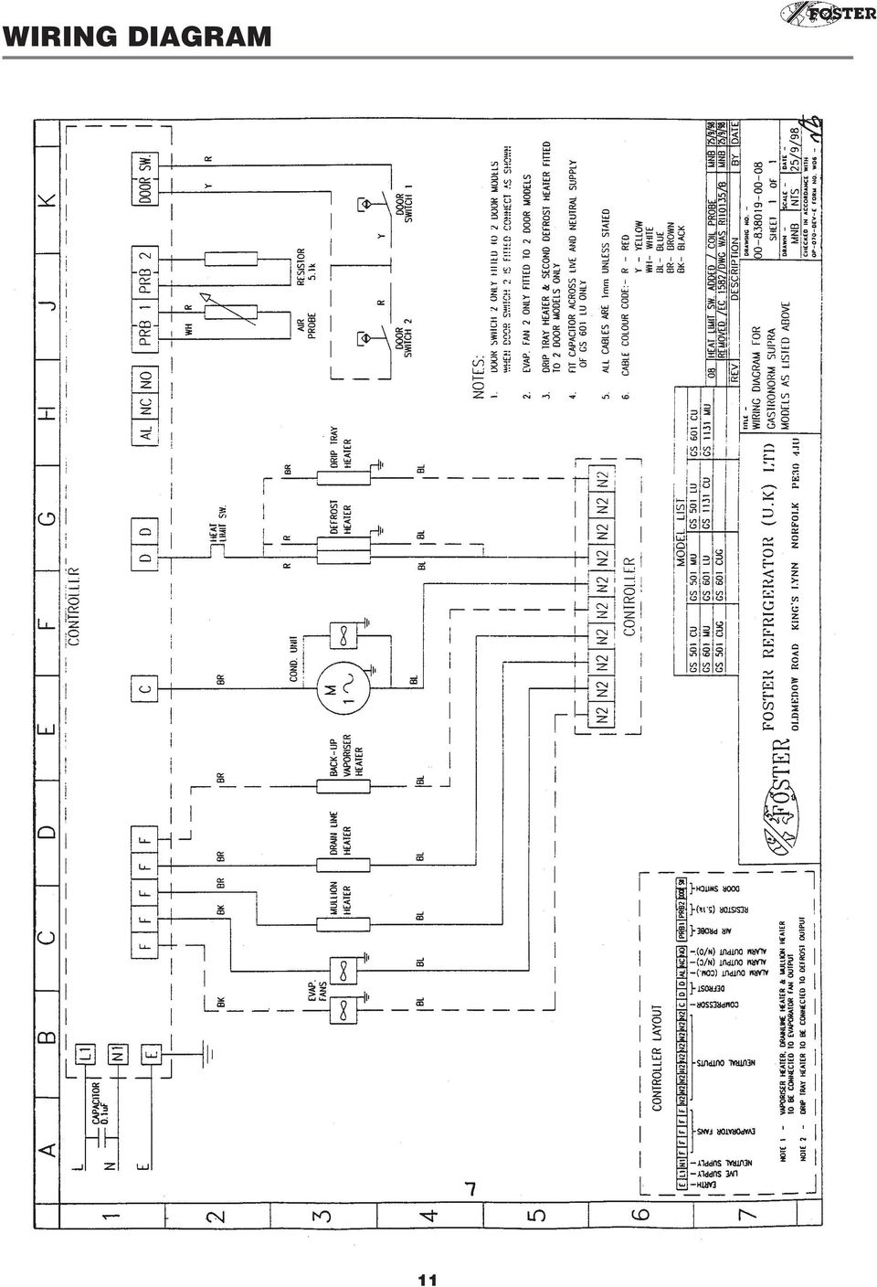
11 WIRING DIAGRAM 11
12 2. CONTROLLER OPERATION FOR CABINETS FROM 1994 TO SERVICE DATA One function of the controller is to provide certain data which may assist engineers in fault diagnosis. The function is LLL in factory set parameters. Access into this function is described in the general operating instructions. Function L1 The data displayed shows the time in hours since the last defrost. This can be of help if a complaint of icing up of the evaporator has been received as this allows the engineer to check that defrost occurs and whether under certain circumstances the defrost period is long enough. L2 In the event of high frequency door opening the value is displayed between 0 and 10. This value is a percentage of the door opening time. Display Door Operation 00 Door closed for 100% of the time. 1 Door has been open for 10% of the time. 2 Door has been open for 20% of the time. 3 Door has been open for 30% of the time. 4 Door has been open for 40% of the time. 5 Door has been open for 50% of the time. 6 Door has been open for 60% of the time. 7 Door has been open for 70% of the time. 8 Door has been open for 80% of the time. 9 Door has been open for 90% of the time. 10 Door has been open for 100% of the time. This data can be useful if an engineer is called to investigate poor performance / high cabinet temperature as he can see from the factor displayed if heavy door usage could be the cause of the performance experienced. L3 The data displayed will be the door open factor (L2) at the time of the last overtemperature warning occurred. The values displayed will change automatically as the operation of the cabinet changes. It is not possible to change the values using the increment and decrement buttons. 2.2 INTRODUCTION This is a multi-function microprocessor digital temperature controller which not only controls and displays the cabinet temperature but has other features and displays. 2.3 DISPLAYS Compressor. The cycle of the compressor is indicated by means of a green LED adjacent to the symbol on the facia. When illuminated the compressor is running during the normal running operation or during defrost if the hot gas method is used. 12

13 2.3.2 Evaporator Fan. The operation of the evaporator is indicated by means of a green LED adjacent to the symbol whilst it is illuminated. When the door is opened the green LED will flash. When closed it will revert back to a solid display Condenser Clean. Adjacent to the condenser symbol is a green LED that illuminates if the compressor run time exceeds the value entered in the service programme (the value is based on hundreds of hours). If illuminated clean the condenser and re-set the compressor run hours in the customer programme C Food Temperature Value. The temperature of the food within the cabinet is monitored via the microprocessor which calculates from the air sensing probe the stored food temperature. If this temperature is within the high/low food temperature conditions set within the factory service parameters, the green LED at the top left hand corner of the display window will be illuminated. If it is outside the high/low settings the red LED adjacent to the! symbol will be illuminated. It should be noted that as the monitoring system simulates actual food there will be a delay in reaching the safe conditions after initial start up of the cabinet. This time could be up to 6-8 hours depending on storage temperature. 2.4 PARAMETER PROGRAMMING AND OPERATING INSTRUCTIONS The controller is a multi-function microprocessor having five levels of control operation. The end user has access only to one level limiting accidental changing of operation parameters Switching On. With power connected to the cabinet the display on the controller fascia will be Switch on by depressing the on/off button. The display will show actual internal temperature plus compressor and evaporator fan LED s User Operation. Cut out temperature Press SET display SET Press SET again display C1 Release display cut out temperature To adjust press or buttons: during this process as the or buttons is pressed the parameter will be displayed and releasing it will show the value. As the button is continuously pressed the value will change. When the required value is set cease pressing the or buttons To exit operation press SET display C2. Hold SET press display FIN. Release both buttons. The cabinet will operate to the new value. 13

14 To change high/low alarm setting Press SET display SET. Press SET display C1. Release display value of C Press SET display C2 (high temp alarm). Release display value of C2. To adjust press or as instruction page Press SET display C3 (low temp alarm). Release display value of C3. To adjust press or as instruction page Press SET display C4 (condenser clean, hours reset). Release display value compressor run hours. To reset to zero as instruction page 4. To exit programming and allow the cabinet to operate normally Press SET display C1. Hold SET and press button display FIN Release both buttons for normal operation. NOTE: If no changes are made during a programming operation for 2 minutes, the controller will reset itself automatically for normal operation. 2.5 ENTERING FACTORY SET AND PROGRAMMING MODE Press and hold SET display SET. Press whilst still holding SET display FIN. Release display FIN. Press on/off I/O whilst still holding SET display LLL. Release all buttons. To change parameter in information mode Press SET display L1. Release display value Press SET display L2 Release display value Press SET display L3. Release display value. To exit without entering any other value Press SET display L1. Press whilst still holding SET display SET. Release whilst still holding SET display FIN. Release both buttons. 14

15 2.5.5 Display Factory Parameter. Access to the Factory Parameter settings is made by first entering the User Programme C1 to C4. Holding down the SET key and pressing the key will cause the controller to display FIN. Releasing the key and depressing the I/O (with the SET key still pressed) will cause the controller to display LLL. Pressing the SET key will scroll through the parameters L1, L2 and L Display / Amend Parameters P1 - P7. Holding the SET key and pressing the key will cause the controller to display OPS. Pressing the SET key will scroll through the parameters P1 to P7. Parameter values may be altered using the or key Display / Amend Parameters D1 - D7. Holding the SET key and pressing the key will cause the controller to display df. Pressing the SET key will scroll through the parameters D1 to D7. Parameter values may be altered using the or key Display / Amend Parameters A1 - A6. Holding the SET key and pressing the key will cause the controller to display AL. Pressing the SET key will scroll through the parameters A1 to A6. Parameter values may be altered using the or key Exit Factory Parameters. To exit Factory Parameter Programming and return to normal operation of the controller, the SET key must be held down and the must be pressed. While both buttons are pressed, the display will show FIN and releasing the buttons will return the controller to normal operation. Note, while in the programming mode, if no button is pressed for a period of thirty seconds, the controller will revert to normal operation Defrost. During the Defrost operation the display will show DEF. The evaporator indicator will be off. At the end of the defrost operation there will be a drain down period when neither the compressor or evaporator will run, therefore both indicator lights will be off. During this period DEF will be displayed. Upon completion of the drain down period, the Recovery operation is initiated with the display showing REC. The compressor will run and the green compressor on indicator will illuminate. On completion of the fan delay period (either by temperature or time) the evaporator fan will run with the green fan indicator LED illuminated. At the end of the Recovery time the display will revert back to displaying the internal cabinet temperature. To initiate a MANUAL DEFROST press and hold the defrost button, press the show DEF, release both buttons. The defrost will be the same as an automatic defrost. button, the display will 15

16 2.7 FACTORY SET PARAMETERS SET No. CABINET MODELS 1 GS 501, 601, 1131, 1351, 2101 HT GS 501, 601, 1131, 1351, 2101 HTR GS 501, 601, 1131 HU GS 501, 601, 1131 HUR GS ALL (High Temp Section) HLT 2 GS 501, 601, 1131 WT GS 501, 601, 1131 WTR GS 501, 601, 1131 WU GS 501, 601, 1131 WUR 3 GS 601, 1131 FT 4 GS 501, 601, 1131, 1351 LT 5 GS 501, 601, 1131, 1351 MT 6 GS 501, 601, 1131, 1351 CT SET No. CABINET MODELS 7 GS 2101 MT GS 501, 601, 1131, 1351, 2101 MTR GS 501, 601, 1131 MU GS 501, 601, 1131 MUR 8 GS 2101 CT GS 501, 601, 1131, 1351, 2101 CTR GS 501, 601, 1131 CU GS 501, 601, 1131 CUR 9 GS 501, 601 LU GS ALL (Low Temp Section) HLT 10 GS 501, 601, 1351 LTR GS 1131 LUR 11 GS 2101 LT GS 2101 LTR GS 1131 LU Parameter Set No Parameter Temperature Set Point C C1 High Food Temp Alarm C C2 Low Temp Food Alarm C C3 Condenser Clean Interval C C4 Time Since Last Defrost L1 L1 Door Open Factor L2 L2 Door Open Factored At Last Alarm Cond. L3 L2 Temperature Differential P P1 Condenser Clean Interval P P2 Compressor Rest Time P P3 Food Probe Offset P P4 Maximum Set Point P P5 Minimum Set Point P P6 Fans On In Defrost P P7 Defrost Type D D1 Defrost Per Day D D2 Termination Temperature D D3 Termination Time D D4 Drain Down Time D D5 Fan Delay Time D D6 Fan Delay Temperature D D7 Door Alarm Delay A A1 Alarm Required A A2 Probe Failure Response A A3 Max High Alarm A A4 Min Low Alarm A A5 Recovery Time A A6 16

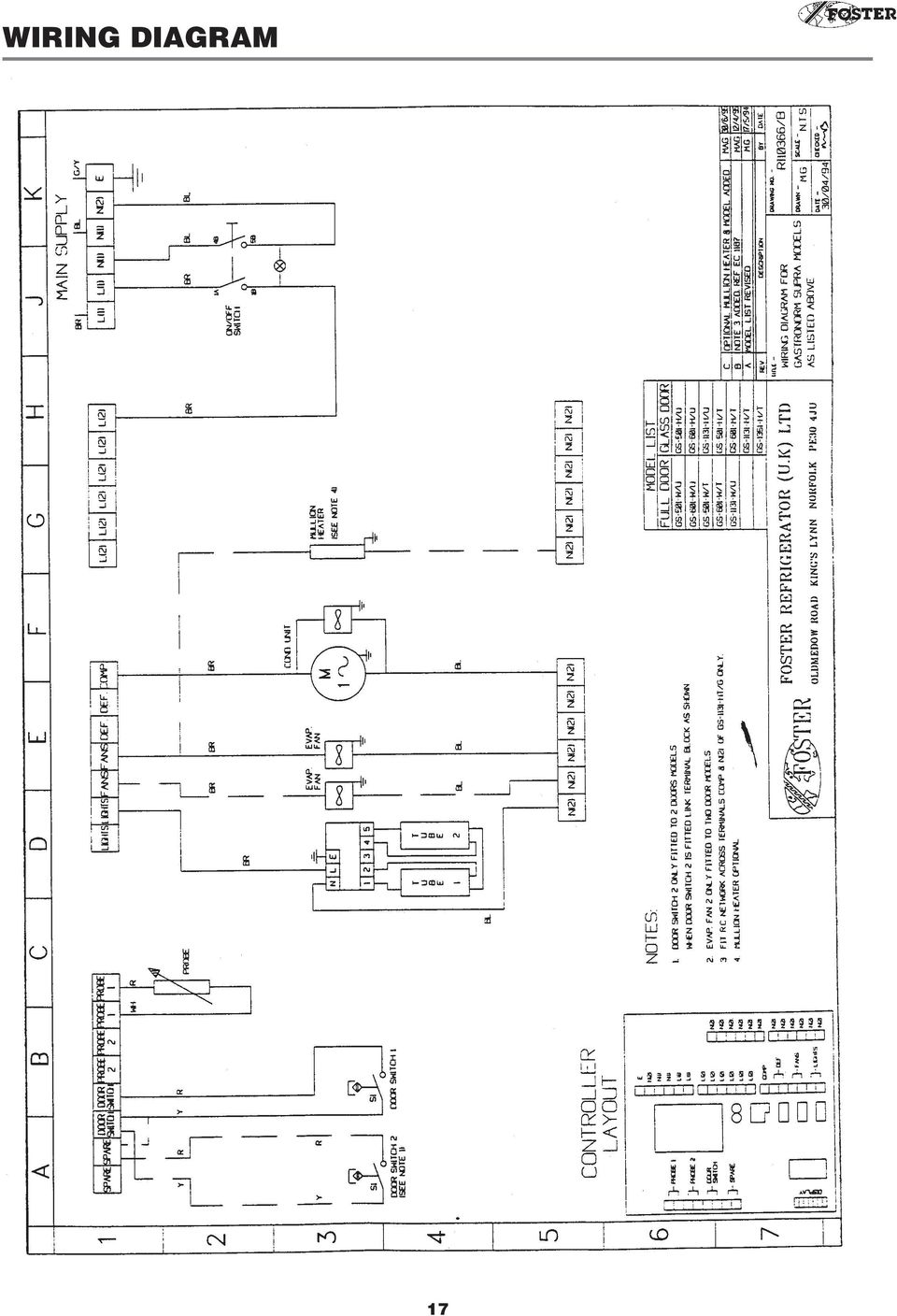
17 WIRING DIAGRAM 17
18 WIRING DIAGRAM 18

19 WIRING DIAGRAM 19

Undercounter & Slimline Cabinet Range HR/LR 120 HRB/LRB120 HR/LR 140 HR/LR 150 HR/LR 200 HR/LR 240 HR/LR 360 HR/LR 410
 Undercounter & Slimline Cabinet Range HR/LR 120 HRB/LRB120 HR/LR 140 HR/LR 150 HR/LR 200 HR/LR 240 HR/LR 360 HR/LR 410 CONTENTS PAGE Introduction 1 to 2 2. Controller and operation 3 to 4 3. Controller
To suit Daikin FDY "F" Series and FD "F" Series. (and other models incorporating BRC1B62/52 Remote Controller)
") OPERATION MANUAL Split System Ducted Air Conditioner To suit Daikin FDY "F" Series and FD "F" Series AIR CONDITIONER A hr o C (and other models incorporating BRC1B62/52 Remote Controller) Dear Owner, Thank
OPERATION MANUAL Split System Ducted Air Conditioner To suit Daikin FDY "F" Series and FD "F" Series AIR CONDITIONER A hr o C (and other models incorporating BRC1B62/52 Remote Controller) Dear Owner, Thank
Owner s Manual. Walk-in Monitoring System 100. Cooler is Better! TM. Used in UL Listed Door Panel Assemblies
 REV. G Cooler is Better! TM Owner s Manual Walk-in Monitoring System 100 Used in UL Listed Door Panel Assemblies American Panel Corporation 5800 S.E. 78th Street, Ocala, Florida 34472-3412 Phone: (352)
LG Air Conditioning Multi F(DX) Fault Codes Sheet. Multi Split Units
 Fault Codes Sheet. Multi Split Units") Multi Split Units If there is a fault on any LG Multi unit, an Error mark is indicated on the display window of the indoor unit, wired-remote controller, and LED s of outdoor unit control board. A two
Multi Split Units If there is a fault on any LG Multi unit, an Error mark is indicated on the display window of the indoor unit, wired-remote controller, and LED s of outdoor unit control board. A two
Duet Condensing Unit/Cooler
 Duet Condensing Unit/Cooler Technical Manual DISPOSAL REQUIREMENTS If not disposed of properly all refrigerators have components that can be harmful to the environment. All old refrigerators must be disposed
THERMO KING TRUCK & TRAILER UNIT ALARM CODES THIS DOCUMENT SHOWS ALL CURRENT ALARM CODES FOR THERMO KING TRUCK AND TRAILER UNITS.
 THERMO KING TRUCK & TRAILER UNIT ALARM CODES THIS DOCUMENT SHOWS ALL CURRENT ALARM CODES FOR THERMO KING TRUCK AND TRAILER UNITS. NOT ALL CODES ARE POSSIBLE ON ANY INDIVIDUAL UNIT. IF THE ALARM APPLIES
ecomax Instructions for use Wall hung room sealed fan assisted condensing boilers For the user
 For the user Instructions for use ecomax Wall hung room sealed fan assisted condensing boilers ecomax 63/ E ecomax 68/ E ecomax 6/ E ecomax 635 E ecomax 84/ E ecomax 88/ E ecomax 835 E GB Table of contents
Drayton Digistat +2RF
 Drayton Digistat +2RF T Programmable Room Thermostat Wireless 24 Hour Model: RF700/22090 Power Supply: Battery - Thermostat Mains - Digistat SCR Invensys Controls Europe Customer Service Tel: 0845 130
Technical Manual. FAN COIL CONTROLLER COOLING or HEATING ANALOG or PWM Art. 119914 631001A
 COOLING or HEATING ANALOG or PWM Art. 119914 631001A TOTAL AUTOMATION GENERAL TRADING CO. LLC SUITE NO.506, LE SOLARIUM OFFICE TOWER, SILICON OASIS, DUBAI. UAE. Tel. +971 4 392 6860, Fax. +971 4 392 6850
Vertical Display and Storage B1350-2. SKOPE Gen2: Three Door Chiller
 Vertical Display and Storage User Manual MAN1227 Rev. 3.0 March 2008 edition CONTACT ADDRESSES Designed and Manufactured by New Zealand SKOPE INDUSTRIES LIMITED PO Box 1091, Christchurch New Zealand Freephone:
Commercial Refrigeration Temperature and Defrost Controls
 Commercial Refrigeration Temperature and Defrost Controls UNI-LINE PRODUCT KNOWLEDGE 2010 Invensys. All Rights Reserved. The names, logos, and taglines identifying the products and services of Invensys
USER MANUAL EXTROLLER
 COAIRE SCREW AIR COMPRESSORS USER MANUAL EXTROLLER SERIAL NO. : MODEL NO. : CAUTION For proper and safe use of the compressor, please follow all instructions and safety precautions as identified in this
B/S/H/ Error codes and service programmes PH
 1 ERROR CODES AND APPLIANCE MESSAGES... 3 1.1 Complete overview of all error codes (in order)... 3 Automatic switch-off... 3 Display is dark and any individual LEDs are lit... 3 E 005... 3 E 011... 3 E
Maxi Pressurisation Units (Maxi, Maxi Plus & HP)
") Maxi Pressurisation Units (Maxi, Maxi Plus & HP) Installation and Maintenance Instructions Contents 1 Dimensions 3 1.1 Installation 4 1.1 Mains/boosted cold water inlet 4 1.2 Connection to the system 5
Maxi Pressurisation Units (Maxi, Maxi Plus & HP) Installation and Maintenance Instructions Contents 1 Dimensions 3 1.1 Installation 4 1.1 Mains/boosted cold water inlet 4 1.2 Connection to the system 5
Instruction manual for Firstline FCS12000CH
 Instruction manual for Firstline FCS12000CH Contents Introduction... 2 Safety Awareness... 3 Safety Awareness... 4 Name of Parts... 5 Name of Parts... 6 Remote Controller Preparation... 7 Operation of
Operations Manual Blast Chiller
 Operations Manual Blast Chiller ADE- 2039-A Page 1 of 14 Contents Page 1 What is the Adande System 3 2 Adande Technology Explained 3 3 EC Declaration of Conformity 4 4 Storage of Product 5 5 Operating
Operational Overview and Controls Guide. Two or Three Pump IronHeart Lite with Variable Frequency Drives
 DOCUMENT: ECSEQ6-0 EFFECTIVE: 09/23/10 SUPERSEDES: Operational Overview and Controls Guide Two or Three Pump IronHeart Lite with Variable Frequency Drives 6700 Best Friend Road. Norcross, GA 30071. (770)
Walk-in Monitoring System 200
 REV. 1/18/16 Cooler is Better! TM Walk-in Monitoring System 200 Used in UL Listed Door Panel Assemblies American Panel Corporation 5800 S.E. 78th Street, Ocala, Florida 34472-3412 Phone: (352) 245-7055
User manual. Atec. 086L0130 Rev. 1 EN
 User manual Atec 086L0130 Rev. 1 EN Thermia Värme AB reserves the right to make changes to components and specifications without prior notice. 2010 Thermia Värme AB. The Swedish language is used for the
SECURIT 800L+ CONTROL PANEL
 USER MANUAL SECURIT 800L+ CONTROL PANEL COMPANY PROFILE IntelliSense have been successfully making security products for over 20 years and lead the security industry throughout the world with many innovative
User manual. 086U6297 Rev. 9 EN
 User manual Atria Atria Duo Atria Duo Optimum Atria Optimum Comfort Diplomat Diplomat Duo Diplomat Duo Optimum Diplomat Duo Optimum G2 Diplomat Optimum Diplomat Optimum G2 086U6297 Rev. 9 EN Thermia Värme
R22. K Control. Indoor Unit. Nomenclature. Compatibility PL H 3 G K H B. Unit style Heat Pump Horse Power
 R22. K Control. Indoor Unit. Nomenclature. PL H 3 G K H B Compatibility Unit style Heat Pump Horse Power Control Boost Heaters R22. K Control. Outdoor Unit. Nomenclature. PU H 3 Y K A Compatibility Outdoor
ITC-308 Plug and Play Temperature Controller
 ITC-308 Plug and Play Temperature Controller 1. Overview ITC-308 is an easy-to-use, safe and reliable dual relay output temperature controller. It can be used as Over-temperature protection and automatic
Operating ambient temperature range: 5ºC to 50ºC Storage temperature range: -30ºC to 70ºC
 HOJA TÉCNICA 1400H101 Edición 01 (02 de 08) www.ako.es GENERAL TECHNICAL SPECIFICATIONS Temperature range: -50ºC to +99ºC type: NTC Total accuracy ( + controller): ±1ºC lead extension with cable AKO-15586:
Regolatori per Refrigerazione Digitali FR... 1-2 canali
 Regolatori per Refrigerazione Digitali FR... 1-2 canali Manuale d Uso 1-2 Channel Regulators for Digital Refrigeration System Manuel Contents Safety warnings Page 20 Technical specifications Page 20 Description
CONTENTS QUICK SETUP & INSTALLATION USER MANUAL. SUPA8 Quick Setup & User Manual
 SUPA8 Quick Setup & User Manual QUICK SETUP & INSTALLATION CONTENTS FACTORY DEFAULTS... 1 INSTALLATION OF THE SECURITY SYSTEM... 2 COMMISSIONING THE DIALLER PANEL... 5 ZONE INPUT CONNECTIONS... 7 PANEL
Drayton Digistat +2RF/+3RF
 /+3RF Programmable Room Thermostat Wireless Model: RF700/22090 Model: RF701/22092 Power Supply: Battery - Thermostat Mains - Digistat SCR Invensys Controls Europe Customer Service Tel: 0845 130 5522 Customer
RS Stock No. 724-4207 Instruction Manual RS-1340 Hot Wire Anemometer
 RS Stock No. 724-4207 Instruction Manual RS-1340 Hot Wire Anemometer EN FR IT DE ES CONTENTS / EN Title CONTENTS Page 1. SAFETY INFORMATION...1 2. INTRODUCTION...2 3. SPECIFICATIONS...3 4. PARTS & CONTROLS...4
AUTOMATIC TRANSFER SWITCH CONTROL UNIT OPERATOR S MANUAL
 ATS-220 AUTOMATIC TRANSFER SWITCH CONTROL UNIT OPERATOR S MANUAL For Use in 208 to 240 Volts Single and 3 Phase ATS Systems With 110Volt AC or DC Control Motors and selenoids 4501 NW 27 ave Miami FL 33142
NL708 (XWA11V) Walk-In Temp / Door /Alarm / Light Module
 Walk-In Temp / Door /Alarm / Light Module") NL708 (XWA11V) Walk-In Temp / Door /Alarm / Light Module 1. General Description 1 2. General Warnings 1 3. Interface 2 4. Temp Alarms Setting 3 5. Programming 3 6. Light Management 4 7. Installation and
NL708 (XWA11V) Walk-In Temp / Door /Alarm / Light Module 1. General Description 1 2. General Warnings 1 3. Interface 2 4. Temp Alarms Setting 3 5. Programming 3 6. Light Management 4 7. Installation and
TC-9102 Series Surface Mount Temperature Controllers
 TC-9102 Series Surface Mount Temperature Controllers General Description & Applications The TC-9102 Series Temperature Controller offers a versatile solution for a wide variety of applications that may
TRANSMITTER RECEIVER THESE INSTRUCTIONS APPLY IN THE UK ONLY THESE INSTRUCTIONS ARE TO BE LEFT WITH THE USER OR AT THE APPLIANCE. Digistat Optimiser
 FITTING AND OPERATING INSTRUCTIONS FOR DIGISTAT OPTIMISER PROGRAMMABLE 7 DAY ROOM THERMOSTAT SYSTEM General information is given in the users instruction leaflet despatched with the appliance and/or on
PSC-A5 Solar Charge Controller Manual
 ( 5A, 12V/24V Output, Double Mode ) 1. Introduction: This controller is suitable for 12V and 24V solar photovoltaic system. The charge and discharge current is 5A. The maximum solar panel for 12V system
Applied Electronics. Commercial Dimming System UPDATE NOTICE
 REV. A Applied Electronics Commercial Dimming System UPDATE NOTICE This notice is to inform the end user of an additional feature added to this DP12/2400 dimming unit. This unit has been outfitted with
3. AIR CONDITIONER CONTROLLER (UNIT)
") 9 3. AIR CONDITIONER CONTROLLER (UNIT) Functions of Full Automatic Air Conditioner ler 1 1. Temp SW 2. Auto SW 3. OFF SW 4. Amb SW 5. Mode SW 6. Blower SW 2 3 10 5 8 7 9 Temperature control: Air mix actuator
9 3. AIR CONDITIONER CONTROLLER (UNIT) Functions of Full Automatic Air Conditioner ler 1 1. Temp SW 2. Auto SW 3. OFF SW 4. Amb SW 5. Mode SW 6. Blower SW 2 3 10 5 8 7 9 Temperature control: Air mix actuator
The Old Brewery Works, Lr Ellacombe Church Rd, Torquay. UK. TQ1 1JH Tel: 01803 295430 Fax: 01803 212819 email: sales@stephenpwales.co.
 : The Old rewery Works, Lr Ellacombe Church Rd, Torquay. UK. TQ1 1JH Tel: 01803 295430 Fax: 01803 212819 email: sales@stephenpwales.co.uk TIM30 MANUAL FOR SETTINGS AND CONFIGURATION Issue 1.0 For Meter
Dixell. Electronic Controls Handbook September 2000. Programming Flow Charts & Parameter Lists for:
 Dixell Electronic Controls Handbook September 2000 Programming Flow Charts & Parameter Lists for: XR100 Series - Refrigeration Controller XT Series - Heating & Cooling Controllers XC Series - Step Controllers
Master Time Clock MTC-200 MTC-400 MTC-600. Users Manual
 Master Time Clock MTC-200 MTC-400 MTC-600 Users Manual Toll Free (888)713-0373 Phone (972)987-4408 FAX (877)720-9291 www.midwest-time.com sales@midwest-time.com TABLE OF CONTENTS TOPIC PAGE GENERAL DESCRIPTION
USER INSTRUCTIONS FOR GET PORTABLE 12k BTU AIR CONDITIONER MODEL No. GPACU12HR
 USER INSTRUCTIONS FOR GET PORTABLE 12k BTU AIR CONDITIONER MODEL No. GPACU12HR CONTENTS Introduction Safety Notes Identification of parts Installation instructions Operation instructions Maintenance Troubleshooting
User Manual THR840DUK Digital Thermostat
 User Manual THR840DUK Digital Thermostat 50051982-001 Rev. A WARNING: This product must be correctly installed and configured to work properly (see pages 12-24). If you are not experienced in wiring electrical
Sigma Control PC INSIDE. 97 psi 187 F R on load
 Sigma Control PC INSIDE 97 psi 187 F R on load Innovation Sigma Control with a PC inside At Kaeser, we pride ourselves on being the world s leading innovator in air system technology. Over twenty-five
Features and Benefits
 Refrigeration 2 eatures and Benefits Based on IR32 Parameters Real Time lock ( RT ) Model Specific (defrost based on real time 7 day 24 hour) HAP (Hazard Analysis and ritical ontrol Point) Alarm Available
USER INSTRUCTIONS FOR 10 LITRE PORTABLE DEHUMIDIFIER MODEL NO. DHMD102
 USER INSTRUCTIONS FOR 10 LITRE PORTABLE DEHUMIDIFIER MODEL NO. DHMD102 THANK YOU FOR CHOOSING YOUR NEW DEHUMIDIFIER. BEFORE USING THE UNIT READ THESE INSTRUCTIONS FULLY AND RETAIN THEM FOR FUTURE REFERENCE
T Sentry 4 Multi-Point Digital Alarm Instruction Manual
 T Sentry 4 Multi-Point Digital Alarm Instruction Manual Introduction The T Sentry4 (TS4) is a microprocessor-based temperature monitoring and alarm device with user programmable high-low alarm setpoints
PLC Control Unit for a CSM-C Steam Compact Clean Steam Generator
 3.635.5275.251 IM-P486-19 CH Issue 2 PLC Control Unit for a CSM-C Steam Compact Clean Steam Generator Installation, Start-up and Operation Manual 1. Safety information 2. General product information 3.
Fused Spur Time Switch
 Fused Spur Time Switch Model No. FST24 24 Hour Timer Model No. FST77 7 Day Timer Installation & Operating Instructions 1. General Information Illuminated screen Sets programmes Sets time and date Reset
USER S MANUAL HSC-24A
 AIRREX AIR CONDITIONER USER S MANUAL HSC-24A Thank you for purchasing an AIRREX AIR CONDITIONER. BEFORE operation please read this user s manual carefully. Keep this manual readily available. It is ESSENTIAL
Portable Air Conditioner. OWNER S MANUAL Read these instructions before use. Model: MF08CESWW. Voltage rating: 115V~60Hz Power rating : 800W
 MODE ALARM Portable Air Conditioner OWNER S MANUAL Read these instructions before use 8 Model: MF08CESWW Voltage rating: 115V~60Hz Power rating : 800W Customer Support : 1-800-474-2147 For product inquiries
CONTENTS 4. HOW TO UNSET THE PANEL...7
 Pi-8 USER MANUAL CONTENTS 1. THE KEYPAD AND ITS OPERATION...3 1.1 DESCRIPTION OF THE KEYPAD LEDS... 3 1.1.1 READY LED (RED)...3 1.1.2 TAMPER LED (RED)...3 1.1.3 POWER LED (GREEN)...3 1.1.4 CIRCUIT LEDs
EBDSPIR-PRM, EBDSPIR-PRM-IP
 Product Guide EBDSPIR-PRM, EBDSPIR-PRM-IP Ceiling PIR presence/absence detector Overview The EBDSPIR-PRM PIR (passive infrared) presence detector provides automatic control of lighting loads with optional
AN500T, AN1000, AN1000T, AN1500, AN1500T AN2000, AN2000T
 Product Instruction Manual Accona AN500T, AN1000, AN1000T, AN1500, AN1500T AN2000, AN2000T Panel heater v16.5/5 Version 3.2 Jan 2015 Contents 1. Important safety points 2. Installation 2.1. Wall mounting
Water-Source Heat Pump
 Application Jauary 1999 Water-Source Heat Pump Application Economizer (Optional) BO-6,7 Discharge Air Temperature (Optional) Heating/Cooling Coil AI-6 Outdoor Air Temperature (Optional) Aux Input AI-5
Water Fired Chiller/Chiller-Heater. WFC-S Series: 10, 20 and 30 RT Cooling
 Water Fired Chiller/Chiller-Heater WFC-S Series: 1, 2 and 3 RT Cooling W E A R E F R I E N D L Y T O T H E E A R T H Water Fired SINGLE-EFFECT Chiller or Chiller-Heater Absorption Principle Cooling Cycle
Aerona Air Source Heat Pumps
 ADDENDUM to INSTALLATION INSTRUCTIONS for Aerona Air Source Heat Pumps DOC.87-05/05 Rev.04 March 2013 ATTENTION INSTALLERS - UPDATED INFORMATION! Your Grant Aerona Air Source Heat Pump has a number of
ELECTRONIC THERMOSTAT AND THERMOMETER With SPEED CONTROL
 148 OLD CONCORD TURNPIKE, BARRINGTON NH 03825 USA TEL (603) 868-5720 FAX (603) 868-1040 1-800-435-6708 E-Mail:sales@seafrost.com www.seafrost.com ELECTRONIC THERMOSTAT AND THERMOMETER With SPEED CONTROL
AIR CONDITIONER WALL CONTROLLER
 AIR CDITIER WALL CTROLLER Operating Instructions Controller Model Numbers LM7 LM7-D LM4 Please Read This Manual Congratulations on your purchase of an ActronAir air conditioning system. This unit has been
EK908FHL - Thermostat for floor heating
 EK908FHL - Thermostat for floor heating EK908FHL is a programmable thermostat designed for floor warming application or helping to limit floor temperature. This thermostat can be used for hot water radiant
*.ppt 11/2/2009 12:48 PM 1
 Digital Compressor Controller *.ppt 11/2/2009 12:48 PM 1 Copeland Scroll Digital Controller Simple Controller That Enables OEM s To Use Digital Scrolls Relieves OEM From Developing Special Controllers
HP 5 Microprocessor Control for Mammoth Water Source Heat Pumps
 HP 5 Microprocessor Control for Mammoth Water Source Heat Pumps Operation and Maintenance Manual Model: 71028004 Applies to: Single Circuit Water-to-Water Twin Circuit Units Without DDC Controls MAMM WHSP
Installation and maintenance instructions. Danfoss Vent
 Installation and maintenance instructions Danfoss Vent 1 Unit design... 2 2 Project planning and installation instructions... 3 2.1 Ventilation...3 2.2 Piping installation....3 2.3 Condensation line...4
HEAT PUMP PROGRAMMABLE THERMOSTAT
 HEAT PUMP PROGRAMMABLE THERMOSTAT SA PM 3 COOL TEMP Form 44014-01 r010408 Model 43168 Owners Manual 1 Congratulations! Heat Pump Programmable Thermostat Model 43168 THERMOSTAT CONTROLS Switches & Buttons...15
CR9971 2 Band Auto Set Dual Alarm Clock Radio ROBERTS. Sound for Generations. Please read this manual before use
 ROBERTS Sound for Generations CR9971 2 Band Auto Set Dual Alarm Clock Radio Please read this manual before use Contents Contents... 1 Controls...2-5 Switching on... 6 Setting the time manually... 6 Setting
Air Conditioning System
 Air Conditioning System 1 Chonan Technical Service Training Center Chonan Technical Service Training Center 2 Objectives To understand the components of air conditioning system. To understand the control
510 / 511 Cardiorespiratory Monitor Preventative Maintenance Test Procedure
 CAS MEDICAL SYSTEMS, INC. 510 / 511 Cardiorespiratory Monitor Preventative Maintenance Test Procedure using the 2301Multi-Function Tester 44 East Industrial Road Branford, CT 06405 USA www.techsrv@casmed.com
Heat Pump Water Heater IOM Manual
 Heat Pump Water Heater IOM Manual Installation Operation & Maintenance This manual is intended as an aid to qualified service personnel for proper installation, operation and maintenance of the heat pump
IMPORTANT USER INFORMATION
 TM C P 8 L L C D U S E R M A N UA L TM Contents Introduction................................. 1 Display Status Blanking........................ 2 IMPORTANT USER INFORMATION.............. 2 Full Setting
Product Data Sheet. User Manual. User Manual MX-4100, MX-4200, MX-4400, Mx-4400/LE & Mx-4800 Fire Alarm Control Panels
 User Manual Product Data Sheet User Manual MX-4100, MX-4200, MX-4400, Mx-4400/LE & Mx-4800 Fire Alarm Control Panels The operation and functions described in the manual are available from Software Versions
Failure code manual. content
 Failure code manual content 一 wall split AC series 2 二 floor standing AC series. 4 三 portable AC series.. 5 四 dehumidifer 6 五 DC inverter single split series...7 六 DC inverter multi-split series 10 1 一
USER MANUAL. Issue 3 - December 2003. Manual Stock No. 73-700 - 00 Software Version 3.0 Zero 88 Lighting Ltd. 2003
 USER MANUAL USER MANUAL If a portable or temporary three phase mains supply is used to power this desk, we recommend that the power supply is unplugged from the mains supply before connecting or disconnecting
Matrix 424/832/832+ ICON & LCD User Manual. Software Version 5 RINS915-2. EN50131-1 Security Grade 2 Environmental Class 2
 Matrix 424/832/832+ ICON & LCD User Manual Software Version 5 RINS915-2 EN50131-1 Security Grade 2 Environmental Class 2 CONTENTS CHAPTER 1: INTRODUCTION... 1 CHAPTER 2: REPLACING THE BATTERIES... 2 CHAPTER
User manual. Solid (FR 98,),
,") User manual Solid (FR 98,), If these instructions are not followed during installation and service, Thermia Värme ABliability according to the applicable warranty is not binding. Thermia Värme AB retains
User manual Solid (FR 98,), If these instructions are not followed during installation and service, Thermia Värme ABliability according to the applicable warranty is not binding. Thermia Värme AB retains
MAGICAR M871A. Car alarm with two-way remote User s guide
 MAGICAR M871A Car alarm with two-way remote User s guide EN MAGICAR M871A Car alarm with two-way remote User s guide TABLE OF CONTENTS Table of contents...2 1. Important notice...4 2. Introduction...4
SERVICE MANUAL REFRIGERATION
 SERVICE MANUAL REFRIGERATION ELECTROLUX HOME PRODUCTS S.p.A. Publication no. Spares Operations Italy 599 36 16-90 Corso Lino Zanussi, 30 031117 I - 33080 PORCIA / PN (ITALY) ITZ/SERVICE/AA Fax +39 0434
User Manual. Humidity-Temperature Chart Recorder. Model RH520
 User Manual Humidity-Temperature Chart Recorder Model RH520 Introduction Congratulations on your purchase of the Extech RH520 Temperature + Humidity Chart Recorder. The RH520 measures and displays Temperature,
POINTS POSITION INDICATOR PPI4
 POINTS POSITION INDICATOR PPI4 Advanced PPI with Adjustable Brightness & Simplified Wiring Monitors the brief positive operating voltage across points motors when they are switched Lights a corresponding
A Class Air Source Heat Pump User Guide
 A Class Air Source Heat Pump User Guide IMPORTANT THIS MANUAL MUST BE LEFT WITH THE USER AFTER INSTALLATION 8/60476/0 Issue 1.03 Contents 1: Introduction 1 2: How the Heat Pump Works 1 2.1 Tips and advice
A/C-HEATER SYSTEM - AUTOMATIC
 A/C-HEATER SYSTEM - AUTOMATIC 1995 Volvo 850 1995-96 Auto. A/C-Heater Systems Volvo 850 * PLEASE READ THIS FIRST * WARNING: To avoid injury from accidental air bag deployment, read and carefully follow
COIN V-SERIES AND EXPRESS- SERIES PROGRAMMING INSTRUCTIONS
 COIN V-SERIES AND EXPRESS- SERIES PROGRAMMING INSTRUCTIONS Programming can be accomplished manually using the machine controls or by connecting to the machine control using a PDA (personal digital assistant),
www.inspection-for-industry.com
 Quality Control Form (TEST RUNNING RECORD FOR AIR HANDLING UNIT) SUB POWER SUPPLY: MAIN POWER V, Hz, CONTROL V, Blower 1 kw, Blower 2 kw, Compressor: (1) kw (2) kw (3) kw (4) kw Heating Element: kw 1.
FG MOISTURE MONITOR Installation & Operation Manual
 FG MOISTURE MONITOR Installation & Operation Manual Issue 3.0 7/20/10 1 Contents SERVICE AND TECHNICAL SUPPORT... 2 INSTALLATION:... 3 MOISTURE SENSOR INSTALLATION:... 3 SENSOR CONNECTOR:... 5 MONITOR
Digital controller with alarm management XR40CX
 1. CONTENTSGENERAL WARNING Digital controller with alarm management XR40CX 1.1 PLEASE READ BEFORE USING THIS MANUAL This manual is part of the product and should be kept near the instrument for easy and
HEATER, AIR CONDITIONING AND VENTILATION
 55-1 GROUP 55 HEATER, AIR CONDITIONING AND VENTILATION CONTENTS GENERAL DESCRIPTION 55-2 HEATER AND AIR CONDITIONING SYSTEM 55-4 HEATER CONTROL 55-6 A/C-ECU 55-7 A/C COMPRESSOR 55-9 CONDENSER 55-9 DUCT
Baxi Platinum Combi HE Range. User s Operating Instructions & Important Warranty Information. Gas Fired Wall Mounted Condensing Combination Boiler
 User s Operating Instructions & Important Warranty Information Baxi Platinum Combi HE Range Gas Fired Wall Mounted Condensing Combination Boiler Please keep these instructions safe. Should you move house,
BARDIC. 4 & 8 Zone Fire Panels Zircon range. Data, installation, operation and maintenance. by Honeywell
 Data, installation, operation and maintenance 4 & 8 Zone Fire Panels Zircon range BARDIC by Honeywell LED flashing LED Continuous FAULT DISABLE/TEST Power General Fault Sounder Fault/ Disable System Fault
06MAR THU 12:38.28. User Manual
 06MAR THU 12:38.28 88.2% 28.0C User Manual 1.0 General Guide Thank you for purchasing your new ADC. We recommend reading this manual, and practicing the operations before using your ADC in the field. The
01-3 0000-00 6810-20 AIR CONDITIONING SYSTEM 1. FFH SPECIFICATION AIR CONDITIONING SYSTEM RODIUS 2004.09
 0000-00 01-3 6810-20 1. FFH SPECIFICATION 01-4 0000-00 2. SYSTEM LAYOUT AND COMPONENTS 0000-00 01-5 01-6 0000-00 3. FFH GENERAL INFORMATION The system is to increase the coolant temperature quickly by
HAM841K ALARM CONTROL PANEL FOR COMMERCIAL AND RESIDENTIAL SECURITY SYSTEMS
 ALARM CONTROL PANEL FOR COMMERCIAL AND RESIDENTIAL SECURITY SYSTEMS USER MANUAL USER MANUAL ALARM CONTROL PANEL FOR COMMERCIAL AND RESIDENTIAL SECURITY SYSTEMS INTRODUCTION The (HA-841K) is a complete
BlueSolar Pro Remote Panel For BlueSolar PWM-Pro charge controllers 12/24V 5, 10, 20, 30A Article number SCC900300000
 Manual EN BlueSolar Pro Remote Panel For BlueSolar PWM-Pro charge controllers 12/24V 5, 10, 20, 30A Article number SCC900300000 Contents EN 1.Important safety instructions... 2 2. Installation... 2 3.Product
Integrating Sound Level Meter and Datalogger
 USER GUIDE Integrating Sound Level Meter and Datalogger Model 407780A Introduction Thank you for selecting the Extech Instruments Model 407780A. This device is shipped fully tested and calibrated and,
SCORPION. micron security products
 SCORPION 4120 6020 & 8020 USER INSTRUCTIONS Thank you for purchasing a Quality Micron Security Alarm Controller. Micron product is manufactured to exacting quality standards. We understand the importance
User Guide. rev. 08/11. RENTAL SALES SERVICE LOGISTICS www.quirksaustralia.com.au Toll free number: 1800 804 627
 User Guide rev. 08/11 RENTAL SALES SERVICE LOGISTICS www.quirksaustralia.com.au Toll free number: 1800 804 627 Acknowledgement Thank you for purchasing this Quirks Medisafe Refrigerator. This refrigerator
SECURITY ALARM CONTROL PANEL QUICK SETUP & USER MANUAL
 SECURITY ALARM CONTROL PANEL QUICK SETUP & USER MANUAL PINKERTON Quick Setup & User Manual QUICK SETUP & INSTALLATION CONTENTS FACTORY DEFAULTS...1 INSTALLATION OF THE SECURITY SYSTEM...2 COMMISSIONING
User Guide Premier Elite 24/48/88/168/640
 User Guide Premier Elite 24/48/88/168/640 INS221-4 Overview Introduction Users of the alarm system will be assigned a unique 4, 5 or 6 digit User code, and may be assigned a Proximity Tag. User codes are
PAC1 Door Access Controller
 PAC1 Door Access Controller Series 2 IMPORTANT DIFFERENCES FROM SERIES 1 1. A PACDL data logger revision 4.0 or higher attached to the DLOG terminal is able to program all features (i.e. times, relay type,
Communicating Wall Control Installation Manual TSTAT0101SC
 Communicating Wall Control Installation Manual TSTAT0101SC U.S. Patent No. 7,243,004 U.S. Patent No. 7,775,452 616 01 1017 02 08/07/12 Safety Considerations... 7 Introduction... 8 Quick Start... 9 Set
Sensi TM. Wi-Fi Programmable Thermostat MANUAL OPERATION. Version: March 2016 2016 Emerson Electric Co. All rights reserved.
 Sensi TM Wi-Fi Programmable Thermostat MANUAL OPERATION Version: March 2016 2016 Emerson Electric Co. All rights reserved. Contents MANUAL OPERATION GUIDE Buttons and Icons 3 Basic Functionality 4 Manual
INSTALLATION OPERATING & MAINTENANCE MANUAL
 INSTALLATION OPERATING & MAINTENANCE MANUAL Basic Climatic TM Controller Ecologic English November 2002 CONTENTS PAGE GENERAL DESCRIPTION 3 USER INTERFACE 4 The keypad incorporated on the unit 4 The keypad
FIREDEX 2200. Conventional Fire Panels
 68 Flexible, high specification system Choice of 1, 2, 4 or 8 zones Simple one-shot auto-reset user test facility Approved to EN54 Maintenance free poly switch circuit protection, with auto reset Class
Owner s Guide and Installation Instructions
 Owner s Guide and Installation Instructions Electronic Continuous Flow Gas Indoor Water Heater 864, series 027 models INSTALLER: The ONLY suitable flue parts are certified Rheem coaxial flue components
BACK PRESSURE MONITOR Operator Display with Exhaust Temperature KIT 194-722
 HEWITT INDUSTRIES 5492 BOLSA AVE. HUNTINGTON BEACH, CA 92649 PH. (714) 891-9300 FAX. (714) 897-7632 WEBSITE: www.hewittindustries.com E-MAIL: sales@hewittindustries.com BACK PRESSURE MONITOR Operator Display