4ms Noise Swash Module
|
|
|
- Raymond Patterson
- 7 years ago
- Views:
Transcription

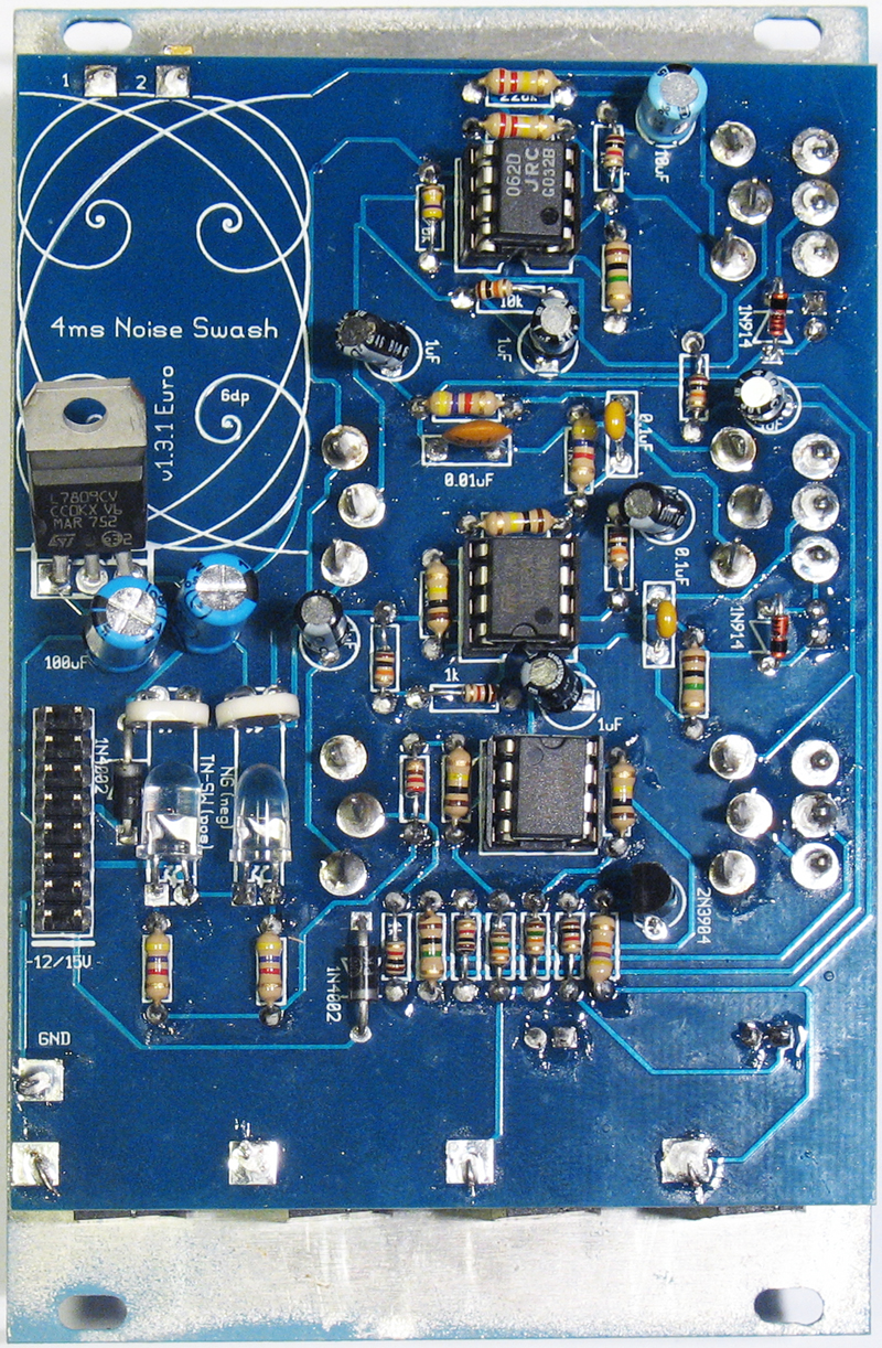
1 4ms Noise Swash Module Kit Builder's Guide for PCB v1.3.1 Eurorack format Noise Swash Module This guide is for building the 4ms Swash module in Eurorack format. The kit includes all the parts you need. Download hi-res PDF version at Tools/supplies Needed: Soldering iron and solder Flush snips Needlenose pliers Wrenches for tightening panel nuts Small flat-head screwdriver for knobs Masking tape or electrical tape Get comfortable, get all your tools together, take a deep breath... and enjoy!

2 Step 1: Resistors Insert and solder the resistors. After soldering, snip the leads nearly flush to the PCB (you'll be snipping the leads flush on all the components after soldering). Save some of the lead snippings for later steps. The Swash has 27 resistors: 1M x 3 (brown black green) 470k x 1 (yellow violet yellow) 220k x 2 (red red yellow) 100k x 4 (brown black yellow) 10k x 4 (brown black orange) 4k7 x 4 (yellow violet red) 1k x 5 (brown black red) 220 x 1 (red red brown) 47k x 1 (yellow purple orange) 15k x 2 (brown green orange) Step 2: Diodes and transistor Insert and solder the four diodes and one transistor. The diodes have an orientation such that the end marked with a black or white band points in the same direction as the arrow on the PCB. The transistor also is orientated such that its curved and straight edges match the outline on the PCB 1N4002 diode (black) x 2 1N914 diode (red/glass) x 2 2N3904 transistor x 1
. B.")
3 Step 3: IC Sockets, Header pins, and Voltage regulator A. Insert and solder the three 8-pin IC sockets. The notch in the sockets points towards the notch drawn in white on the PCB (one points up, two point down). B. Insert and solder the Voltage Regulator (7809), matching the large metal tab of the package to the marks drawn on the PCB. C. Insert and solder the 16-pin power connector (header pins). Step 4: Capacitors Insert and solder the 12 capacitors. The 1uF, 10uF, and 100uF capacitors have an orientation such that the long lead goes in the square hole, and the short lead (marked by a black or white stripe on the body of the cap) goes in the round hole. Capacitors 0.01uF ( 103 ) x 1 0.1uF ( 104 ) x 2 1uF x 6 10uF x 1 100uF x 2

4 Step 5: LED/CdS cells Insert the two large (5mm) LEDs into the PCB. The short lead of the LED is the negative and it goes in the round hole. Also, if you look down the barrel of the LED, one edge is flattened, which indicates the negative side. Insert the photo cells into their spots on the PCB. Bend over the LEDs and the photocells 90 degrees so that they point at each other (see photo). Solder all four components. Step 6: Prepare for mounting A. Break off the side tabs on the 4 jacks. B. Mount the 4 jacks and the 10-turn pot to the panel with the orientations as shown. Tighten the nuts down finger tight. You may need to nudge them slightly in a later step. C. Strip the entire 4" piece of wire. Starting at the Mood jack, use it to connect the ground tabs of the 4 jacks. Leave a 1" or longer tail off the OUT jack (see close-up photo).
. See photo previous page. B. Prepare the pots Remove the nut and both washers from the pots.")
5 Step 7: Mounting A. Prepare the switches Remove the top nut and one washers from the flip switches. Cover the metal portion of the switch body with masking tape (or any insulator). This keeps the pots from shorting out to the switches. Insert the switches into the PCB (do not solder yet). See photo previous page. B. Prepare the pots Remove the nut and both washers from the pots. Then break off the tab on the top of the pot as shown in the photo. Insert the pots into the PCB (do not solder yet) See photo previous page. C. LEDs Insert the LEDs with the long lead going into the square hole. (do not solder yet) D. Put the panel on: Keeping the PCB held in one hand, lower the panel (with the jacks attached) onto the pots/switches so the holes line up with the pots and switches. Wiggle things around as you shimmy it down so that the threads of the controls push through the panel. C. Put the nuts on: When all the controls are lined up, put a washer and nut over each pot and switch and tighten them down finger-tight (the washer under the switch nut is optional). Verify that the LEDs are still in place and check to make sure all the controls are roughly vertical. Now tighten the 8 nuts down with a wrench, making sure the pot or switch doesn't rotate while you tighten. D. Check for contact: Flip the board over so you can see the gap between the PCB and the bottom of the pots. Verify that the PCB is in full contact with the bottom of each jack, and the tips of the switches just barely stick out through the PCB. The PCB may be slightly skewed (not parallel) to the panel, this is OK.

6 Step 8: Soldering the jacks and controls. A. Solder the jacks Attach each jack to the PCB by running a small piece of snipped resistor lead or wire through the hole in the PCB and the hole in the jack tab. You may need to nudge each jack a bit to get the holes to line up. Bend this lead/wire over into a "U" shape so that it doesn't fall out. Solder each one from the top and bottom sides. Snip off the excess wire. B. Run the jack ground wire Thread the tail end of the ground wire from step 6 through the pad marked GND. Solder and snip off excess wire. C. Solder the switches Solder the switch leads, pushing the PCB down lightly so that the leads stick out a tiny bit. Next solder all the pot leads. D. Solder the LEDs Push each LED head down so it sits in the hole in the panel. Splay the leads slightly so it stays in place while you solder it. Snip the excess lead off when done. E. Solder the 10-turn pot Wire the 10-turn pot by soldering one piece of lead/wire from the hole marked "2" to the tab on the pot directly below. Solder another piece of wire from the hold marked "1" to the middle tab on the pot. (see photo) F. Install the knobs Flip the unit over and tighten all the nuts very tightly. Attach the knobs with a small flat-head screwdriver.
7
8
step 1 Unpack the lunchbox And check whether you have got all the components~ If you have questions please contact us at: info@unitunlikely.
 step 1 Unpack the lunchbox And check whether you have got all the components~ If you have questions please contact us at: info@unitunlikely.com This part is called the PCB (printed circuit board). All
BUILDING INSTRUCTIONS
 etap2hw 38 mm I2C to LCD Interface BUILDING INSTRUCTIONS October 2013 P. Verbruggen Rev 1.01 15-Oct-13 Page 1 Table of Contents Chapter 1 General Information 1.1 ESD Precautions 1.2 Further Supplies 1.3
MGB Chrome Bumper Conversion
 MGB Chrome Bumper Conversion Installation Instructions For 1974 1/2-1980 MGB This kit requires cutting, welding, and painting. Professional installation recommended. Note: Every MGB body is slightly different
WHO ANSWERED FIRST? FIND OUT WITH THIS QUIZ BUZZER KIT
 WHO ANSWERED FIRST? FIND OUT WITH THIS QUIZ BUZZER KIT BUILD INSTRUCTIONS Before you put any components in the board or pick up the soldering iron, just take a look at the Printed Circuit Board (PCB).
Assembly and User Guide
 1 Amp Adjustable Electronic Load 30V Max, 1 Amp, 20 Watts Powered by: 9V Battery Assembly and User Guide Pico Load is a convenient constant current load for testing batteries and power supplies. The digital
Martin County Amateur Radio Association. Nightfire Kits 1 LED Torch Kit 270016. Contents. Description
 Nightfire Kits 1 LED Torch Kit 270016 1 Contents Nightfire Kits LED Torch Kit 270016... 1 Description... 1 Safety and Assembly of the kit... 6 Required and Useful Tools... 7 Assembly... 8 Checkout and
Cumbria Designs T-1. SSB/CW Filter kit (4.9152MHz) User Manual
 User Manual") Cumbria Designs T-1 SSB/CW Filter kit (4.9152MHz) User Manual CONTENTS 1 INTRODUCTION 2 2 CIRCUIT DESCRIPTION 2 3 ASSEMBLY 2 4 TESTING 4 The Steading Stainton PENRITH Cumbria CA11 0ES UK 1 Introduction
Cumbria Designs T-1 SSB/CW Filter kit (4.9152MHz) User Manual CONTENTS 1 INTRODUCTION 2 2 CIRCUIT DESCRIPTION 2 3 ASSEMBLY 2 4 TESTING 4 The Steading Stainton PENRITH Cumbria CA11 0ES UK 1 Introduction
AXE114S BINARY CLOCK. revolution Revolution Education Ltd. Email: info@rev-ed.co.uk Web: www.rev-ed.co.uk Version 1.1 12/09/08 AXE114.PMD.
 AXE114S BINARY CLOCK Features: The PICAXE binary clock kit tells the time by lighting up blue LEDs in a binary pattern. This is a useful tool for teaching students binary code or simply just confusing/
Modifying the Yaesu FT-847 External 22.625 MHz Reference Input
 Modifying the Yaesu FT-847 External 22.625 MHz Reference Input David Smith VK3HZ Introduction This document describes the modification of an FT-847 to allow an external 22.625 MHz Reference oscillator
Electronics and Soldering Notes
 Electronics and Soldering Notes The Tools You ll Need While there are literally one hundred tools for soldering, testing, and fixing electronic circuits, you only need a few to make robot. These tools
TEACHING RESOURCES SCHEMES OF WORK DEVELOPING A SPECIFICATION COMPONENT FACTSHEETS HOW TO SOLDER GUIDE GET IN TUNE WITH THIS FM RADIO KIT. Version 2.
 TEACHING RESOURCES SCHEMES OF WORK DEVELOPING A SPECIFICATION COMPONENT FACTSHEETS HOW TO SOLDER GUIDE GET IN TUNE WITH THIS FM RADIO KIT Version 2.0 Index of Sheets TEACHING RESOURCES Index of Sheets
Analog control unit for mobile robots
 Analog control unit for mobile robots Soldering kit for experimentation For Fischertechnik robots and others Most diverse functions Requires no programming Patented sensor technology Summary We are pleased
IntelliChlor Flow-Temperature Switch Replacement Kit Installation Guide
 IntelliChlor Flow-Temperature Switch Replacement Kit Installation Guide Technical Support Sanford, North Carolina (8 A.M. to 5 P.M.) Moorpark, California (8 A.M. to 5 P.M.) Phone: (800) 831-7133 Fax: (800)
Assembly Instructions: Shortwave Radio Kit
 Assembly Instructions: Shortwave Radio Kit MTM Scientific, Inc P.O. Box 522 Clinton, MI 49236 U.S.A Introduction Fig 1: The assembled Shortwave Radio Kit The SHORTWAVE RADIO KIT (#SWRAD) from MTM Scientific
RS232/DB9 An RS232 to TTL Level Converter
 RS232/DB9 An RS232 to TTL Level Converter The RS232/DB9 is designed to convert TTL level signals into RS232 level signals. This cable allows you to connect a TTL level device, such as the serial port on
AstroSystems Digital Setting Circles for Zhumell, GSO, Apertura and Astro-Tech
 AstroSystems Digital Setting Circles for Zhumell, GSO, Apertura and Astro-Tech Components 1 Sky Commander Digital Setting Circle Computer 2 Encoders 10,000 step 1 Sky Commander Digital Setting Circle Manual
ECEN 1400, Introduction to Analog and Digital Electronics
 ECEN 1400, Introduction to Analog and Digital Electronics Lab 4: Power supply 1 INTRODUCTION This lab will span two lab periods. In this lab, you will create the power supply that transforms the AC wall
Total solder points: 205 Difficulty level: beginner 1 2 3 4 5 advanced UNIVERSAL BATTERY CHARGER / DISCHARGER K7300 ILLUSTRATED ASSEMBLY MANUAL
 Total solder points: 205 Difficulty level: beginner 1 2 3 4 5 advanced UNIVERSAL BATTERY CHARGER / DISCHARGER K7300 Automatic (dis)charging of both NiCd and NiMH batteries. ILLUSTRATED ASSEMBLY MANUAL
200W DISCRETE POWER AMPLIFIER K8060
 H8060IP-1 200W DISCRETE POWER AMPLIFIER K8060 Ideal for active speaker system or subwoofer, guitar amp, home theatre systems, instrument amp, etc. Features & Specifications Specifications: Excellent value
Joule Thief 3.0 Kit. June 2012, Rev 1 1 http://www.easternvoltageresearch.com Joule Thief 3.0
 Kit Instruction Manual Eastern Voltage Research, LLC June 2012, Rev 1 1 http://www.easternvoltageresearch.com HIGH BRIGHTNESS LED THIS KIT USES A 1W CREE, HIGH BRIGHTNESS LED. DO NOT STARE AT THIS (OR
Trillium 40 Axis Spring Tensioner Wire Replacement Instructions
 Trillium 40 Axis Spring Tensioner Wire Replacement Instructions 1 Overview The objective is to replace the broken axis spring tensioner wire. This requires the following tasks: 1. Remove the seismometer
Build Your Own Solar Car Teach build learn renewable Energy! Page 1 of 1
 Solar Car Teach build learn renewable Energy! Page 1 of 1 Background Not only is the sun a source of heat and light, it s a source of electricity too! Solar cells, also called photovoltaic cells, are used
Table of Contents. www.hunterfan.com. What to Expect with. Preparation. Tools Needed. Wiring. Hanging the Fan. Blades. Motor Housing.
 www.hunterfan.com Table of Contents What to Expect with Your Installation 30 inches Hanging the Fan Wiring 8 Maintenance, Operation & Cleaning Light Kit 13??? 14 1 9 Troubleshooting 11 5 Blades Motor Housing
Time needed: ~3h for lid replacement only. Add 1h for operation harness in lid and ~2h more for installing drive unit and cable harness in trunk.
 DIY for replacing trunk lid and/or retrofitting electrical operation of trunk lid. This document is meant to be a support and give advice on the procedure but I will take no responsibility for any damage
Document number RS-PRD-00130 Revision 05 Date 20/10/2009 Page 1/30
 Date 20/10/2009 Page 1/30 1. Purpose This document describes the field replacement of the footscan plate cable for these models: 2m hi-end plate SN 11/5/xxx 2m pro plate SN 7/5/xxx 0.5m 2003 hi-end plate
Connecting the Channel A
 20 Edge Lighting. All Rights Reserved. Installation Instructions for Cirrus Channel Suspension T, Tubular Lens w/2sq or 2RD Canopy IMPORTANT INFORMATION - This product is suitable for indoor locations.
BMD16N-SD. version 1.2
 BMD16NSD version 1.2 Feedback decoder with 16 contacts with integrated current detection for the S88bus Compatible with a.o. Märklin Digital, Uhlenbrock Intellibox, Fleischmann TwinCenter and LDT HSI88
DET Practical Electronics (Intermediate 1)
") DET Practical Electronics (Intermediate 1) 731 August 2000 HIGHER STILL DET Practical Electronics (Intermediate 1) Support Materials CONTENTS Section 1 Learning about Resistors Section 2 Learning about
DET Practical Electronics (Intermediate 1) 731 August 2000 HIGHER STILL DET Practical Electronics (Intermediate 1) Support Materials CONTENTS Section 1 Learning about Resistors Section 2 Learning about
AUTOMATIC CALL RECORDER JAMECO PART NO. 2163735
 AUTOMATIC CALL RECORDER JAMECO PART NO. 2163735 Experience Level: Intermediate Time Required: 1-2 Hours This project automatically records phone calls. The program, along with the adapter records each
Micrio WS1 Replacement Wind Speed Sensor and WC1 Replacement Wind Compass Sensor for Raymarine ST50 and ST60 Wind Instruments. Rev 4.
 Micrio WS1 Replacement Wind Speed Sensor and WC1 Replacement Wind Compass Sensor for Raymarine ST50 and ST60 Wind Instruments. Rev 4.1 The Micrio WS1 Wind Speed Sensor and WC1 Compass Sensor are direct
Total solder points: 57 Difficulty level: beginner 1 2 3 4 5 advanced 3 TO 30VDC / 3A POWER SUPPLY K7203 ILLUSTRATED ASSEMBLY MANUAL H7203IP-1
 Total solder points: 57 Difficulty level: beginner 1 2 3 4 5 advanced 3 TO 30VDC / 3A POWER SUPPLY K7203 A power supply for all our kits, based on a stabilised DC voltage of 30V. ILLUSTRATED ASSEMBLY MANUAL
MGA Alternator Conversion
 MGA Alternator Conversion Installation Instructions For 1955 to 1962 MGA PART # 130-078 and #130-088 440 Rutherford St. P.O. Box 847 Goleta, CA 93117 1-800-667-7872 FAX 805-692-2525 www.mossmotors.com
A&A CORVETTE PERFORMANCE C6 BOOST & FUEL GAUGE INSTALLATION INSTRUCTIONS
 A&A CORVETTE PERFORMANCE C6 BOOST & FUEL GAUGE INSTALLATION INSTRUCTIONS 1. Check your gauges before you take them out of the packaging to make sure they are at 0 (zero) psi for both boost and fuel pressure.
The RSGB Centenary Receiver Project Construction Manual
 The RSGB Centenary Receiver Project Construction Manual Page 1 of 12 Introduction This project is intended for those new to radio construction. It is a fairly simple receiver for the 14MHz (20m) amateur
Total solder points: 129 Difficulty level: beginner 1 2 3 4 5 advanced LIQUID LEVEL CONTROLLER K2639 ILLUSTRATED ASSEMBLY MANUAL H2639IP-1
 Total solder points: 129 Difficulty level: beginner 1 2 3 4 5 advanced LIQUID LEVEL CONTROLLER K2639 Forgotten to turn off the tap, leaking washing machines,... Prevention is better than cure. So use this
Kit 106. 50 Watt Audio Amplifier
 Kit 106 50 Watt Audio Amplifier T his kit is based on an amazing IC amplifier module from ST Electronics, the TDA7294 It is intended for use as a high quality audio class AB amplifier in hi-fi applications
K6002 TEMPERATURE CONTROLLER. Specifications
 Total solder points: 169 + 99 + 67 Difficulty level: beginner 1 2 3 4 5 advanced TEMPERATURE CONTROLLER K6002 Unlike a normal thermostat, this kit has two outputs, one for "high" alarm and one for "low"
Owners & Installation Manual for the Sheridan, Mountainair, Pine Valley and Old Forge Ceiling Fan Family
 Owners & Installation Manual for the Sheridan, Mountainair, Pine Valley and Old Forge Ceiling Fan Family Part of the Kiva Lighting Family Custom Lighting and Fans Since 1992 1312 12th St NW Albuquerque,
400W MONO/STEREO AMPLIFIER
 400W MONO/STEREO AMPLIFIER Universal, robust and compact are the words to describe this amplifier. Total solder points: 264 Difficulty level: beginner 1 2 3 4 5 advanced K4005B ILLUSTRATED ASSEMBLY MANUAL
Total solder points: 167 Difficulty level: beginner 1 2 3 4 5 advanced DMX CONTROLLED RELAY K8072 ILLUSTRATED ASSEMBLY MANUAL
 Total solder points: 167 Difficulty level: beginner 1 2 3 4 5 advanced DMX CONTROLLED RELAY K8072 Control a relay by means of the wellknown DMX512 protocol. ILLUSTRATED ASSEMBLY MANUAL H8072IP-1 Features
K8025 VIDEO PATTERN GENERATOR. Check the picture quality of your monitor or TV, ideal for adjustment or troubleshooting.
 K8025 ILLUSTRATED ASSEMBLY MANUAL H8025IP 1 VIDEO PATTERN GENERATOR Check the picture quality of your monitor or TV, ideal for adjustment or troubleshooting. Forum Participate our Velleman Projects Forum
ilan Ethernet Box for 9100 Installation Manual
 ilan Ethernet Box for 9100 Installation Manual 07103-00154 March 11, 2014 Corporate Headquarters: 21405 B Street Long Beach, MS 39560 Phone: (800) 259-6672 Fax: (228) 868-9445 Copyright Notice 2014 Triton.
POCKET AUDIO GENERATOR K8065
 POCKET AUDIO GENERATOR K8065 Great little gadget for service repair, testing, education, etc... ILLUSTRATED ASSEMBLY MANUAL H8065IP-1 VELLEMAN NV Legen Heirweg 33 9890 Gavere Belgium Europe www.velleman.be
GLOLAB Universal Telephone Hold
 GLOLAB Universal Telephone Hold 1 UNIVERSAL HOLD CIRCUIT If you have touch tone telephone service, you can now put a call on hold from any phone in the house, even from cordless phones and phones without
Soldering is easy. here's how to do it. Andie Nordgren (Comics adaptation) Jeff Keyzer. by: Mitch Altman (soldering wisdom) (Layout and editing)
 Jeff Keyzer. by: Mitch Altman (soldering wisdom) (Layout and editing)") Soldering is easy here's how to do it by: Mitch Altman (soldering wisdom) Andie Nordgren (Comics adaptation) Jeff Keyzer (Layout and editing) Download this comic book and share it with your friends! Distribute
Soldering is easy here's how to do it by: Mitch Altman (soldering wisdom) Andie Nordgren (Comics adaptation) Jeff Keyzer (Layout and editing) Download this comic book and share it with your friends! Distribute
Build a Junior Solar Sprint Model Car Kit Materials: 1 PITSCO Ray Catcher Sprint Kit or Solar Made Junior Solar Sprint Kit 1 White Sheet of Plastic
 Build a Junior Solar Sprint Model Car Kit Materials: 1 PITSCO Ray Catcher Sprint Kit or Solar Made Junior Solar Sprint Kit 1 White Sheet of Plastic Coated Paper 2 Balsa Sheets (10-1/2 x4 x3/16 ) 2 Alligator
FTC 2015-2016 DIY Mountain Build Guide
 FTC 2015-2016 DIY Mountain Build Guide Assembly Instructions Check out the DIY2015-2016 Prints and BoM for individual part details. Release 1.0 9/10/15 Page 1 This guide and Bill of Materials are for constructing
VOLUME AND TONE CONTROL - PREAMPLIFIER K8084
 H8084IP-1 VOLUME AND TONE CONTROL - PREAMPLIFIER K8084 When using one of our amplifiers (big or small), you always need a volume control and preferably also a tone control Features & specifications When
Electric Field Mapping Lab 3. Precautions
 HB 09-25-07 Electric Field Mapping Lab 3 1 Electric Field Mapping Lab 3 Equipment mapping board, U-probe, resistive boards, templates, dc voltmeter (431B), 4 long leads, 16 V dc for wall strip Reading
The $25 Son of a cheap timer This is not suitable for a beginner. You must have soldering skills in order to build this kit.
 The $25 Son of a cheap timer This is not suitable for a beginner. You must have soldering skills in order to build this kit. Micro Wizard has been manufacturing Pinewood Derby timers for over 10 years.
SPRITE and BIGFOOT DESKTOP CNC MACHINE KIT ASSEMBLY INSTRUCTIONS
 SPRITE and BIGFOOT DESKTOP CNC MACHINE KIT ASSEMBLY INSTRUCTIONS README FIRST: Thank you for purchasing your MyDIYCNC Desktop CNC Machine Kit. We hope this versatile and innovative machine brings you many
KEYPAD LOCK RETROFIT KIT
 KEYPAD LOCK RETROFIT KIT INSTRUCTIONS FOR ASSEMBLY IMPORTANT READ & SAVE THESE INSTRUCTIONS Tools Required for Assembly 5/32 hex (Allen) wrench #2 Phillips screwdriver Isopropyl alcohol or alcohol wipes
Adafruit Proto Shield for Arduino
 Adafruit Proto Shield for Arduino Created by lady ada Last updated on 2016-08-04 11:06:30 PM UTC Guide Contents Guide Contents Overview Make it! Lets go! Preparation Prep Tools Parts list Parts List Optional
RESISTANCE SUBSTITUTION BOX
 RESISTANCE SUBSTITUTION BOX MODEL RS-400 / K-37 Assembly and Instruction Manual TM Elenco Electronics, Inc. Copyright 1990 Elenco TM Electronics, Inc. Revised 2003 REV-G 753RS400 The Resistance Substitution
HG600/HG800. Hydro-Power Unit. Installation and Operation Guide
 HG600/HG800 Hydro-Power Unit Installation and Operation Guide Copyright 04 HydroSpin, All rights reserved. The data contained in this document is proprietary to HydroSpin. It is disclosed to the receiving
DIY QUAD. Build Manual V.A 2014
 DIY QUAD Build Manual V.A 2014 1 Contents Thanks for purchasing a DIY Quad! These instructions will show you how to assemble a Quad using the Pixhawk autopilot system and ArduCopter/APM:Copter firmware.
GUITAR PREAMPLIFIER WITH HEADPHONE OUTPUT K4102
 H4102IP-1 GUITAR PREAMPLIFIER WITH HEADPHONE OUTPUT K4102 Practice the guitar without disturbing others. Features & Specifications Features: An electric guitar cannot be connected to just any amplifier
The Radio-Kits Digital SWR meter kit Construction and user manual
 The Radio-Kits Digital SWR meter kit Construction and user manual Author - Steve Drury G6ALU List of contents Section Page no. 1. Features and specifications 2 2. Introduction 2. Construction 4. General
GTI VR6 Front Wheel Bearing DIY http://www.gtishrine.com
 GTI VR6 Front Wheel Bearing DIY http://www.gtishrine.com This procedure covers replacing the front wheel bearings. Tools and Parts required: Wheel Bearing Puller w/ ABS adapter. Available for rent from
K8068 BUS DIMMER FOR HOME MODULAR LIGHT SYSTEM ILLUSTRATED ASSEMBLY MANUAL H8068IP-1
 Total solder points: 74 Difficulty level: beginner 1 2 3 4 5 advanced BUS DIMMER FOR HOME MODULAR LIGHT SYSTEM K8068 PLUG - IN module for use with home modular lights system K8006. For electronic transformers!
BMW X5 Tail Lamp Assembly Repair. By Myles H. Kitchen M.H. KITCHEN & ASSOCIATES www.auto-electronic.com Email: MHKitchen@aol.com
 BMW X5 Tail Lamp Assembly Repair By Myles H. Kitchen M.H. KITCHEN & ASSOCIATES www.auto-electronic.com Email: MHKitchen@aol.com INTRODUCTION A common problem experienced by BMW X5 owners is a Check Rear
Total solder points: 115 Difficulty level: beginner 1 2 3 4 5 advanced 4 CHANNEL RUNNING LIGHT K8032 ILLUSTRATED ASSEMBLY MANUAL
 Total solder points: 115 Difficulty level: beginner 1 2 3 4 5 advanced 4 CHANNEL RUNNING LIGHT K8032 Ideal for creating disco light effects, light speed adjustable. Suited for inductive loads. ILLUSTRATED
http://waterheatertimer.org/troubleshoot-rheem-tankless-water-heater.html
 http://waterheatertimer.org/troubleshoot-rheem-tankless-water-heater.html TECHNICAL SERVICE DEPARTMENT Removal, Cleaning, & Reinstallation of the Burner Assembly For models 74 & GT199 Required tools -
7-SEGMENT DIGITAL CLOCK
 57mm 7-SEGMENT DIGITAL CLOCK Large 57mm clock & temperature display with extra unique feature Total solder points: 263 Difficulty level: beginner 1 2 3 4 5 advanced K8089 ILLUSTRATED ASSEMBLY MANUAL H8089IP-1
K128. USB PICmicro Programmer. DIY Electronics (HK) Ltd PO Box 88458, Sham Shui Po, Hong Kong. http://www.kitsrus.com mailto: peter@kitsrus.
 Ltd PO Box 88458, Sham Shui Po, Hong Kong. http://www.kitsrus.com mailto: peter@kitsrus.") K128 USB PICmicro Programmer DIY Electronics (HK) Ltd PO Box 88458, Sham Shui Po, Hong Kong http://www.kitsrus.com mailto: peter@kitsrus.com Last Modified March 31 2003 Board Construction The board is
K128 USB PICmicro Programmer DIY Electronics (HK) Ltd PO Box 88458, Sham Shui Po, Hong Kong http://www.kitsrus.com mailto: peter@kitsrus.com Last Modified March 31 2003 Board Construction The board is
GT3B Hack Kit Install Instructions Written By Austin Hutchison
 GT3B Hack Kit Install Instructions Written By Austin Hutchison Step 1: Remove 4 screws located on top of the radio. 1 Step 2: There are small plastic latches that also hold the top in place. The easiest
Navico-Northstar 2kW JRC Radar Package, Scanner Cable Removal and Replacement
 Navico-Northstar 2kW JRC Radar Package, Scanner Cable Removal and Replacement This work instruction describes the methods and means for which to remove and reinstall optional scanner cable configurations
TEECES DOME LIGHTING SYSTEMS
 This lighting system was designed by John V (Teeces) to be a simple, customizable, expandable and affordable solution for dome lighting. An Arduino micro-controller is used to tell LED driver chips which
HP 36-Port InfiniBand Switch Cable Management Kit Installation Guide
 HP 36-Port InfiniBand Switch Cable Management Kit Installation Guide HP Part Number: 574412-doc Published: May 2009 Copyright 2009 Hewlett-Packard Development Company, L.P. The information contained herein
Anderson Powerpoles. Powerpole Assembly Instructions for SCOUT, NAVIGATOR AND RANGER ROV s
 Anderson Powerpoles Powerpole Assembly Instructions for SCOUT, NAVIGATOR AND RANGER ROV s Anderson Powerpoles Power Connections NEW in 2016!!! ELEC-010E: Power supply connections will be Red/Black Anderson
The Xtal Set Society Newsletter
 The Xtal Set Society Newsletter In this issue (#67) July 1, 2002!This is an exerpt from our July 2002 issue The Quaker Oats Box Crystal Radio Set If we put this set on the NET, would it create Oatmeal
QSI Auto-Focus Mounting Bracket
 QSI Auto-Focus Mounting Bracket The camera mounting bracket makes extensive use of sliding dovetails. The dovetail joint gets immense strength from a trapezoidal pin trapped in a slot. The internal flats
Overnight Sensations Speaker Kit
 Overnight Sensations Speaker Kit Thank you for purchasing the Overnight Sensation cabinet kit. This speaker kit was precision cut using CNC machinery for the best possible fit and finish. With a little
430 Power/Electronics Replacement
 Replacing the main board WARNING Before proceeding, turn off the main power switch and unplug the power cord. Caution Make sure you are properly grounded with an ESD strap before continuing. The main printed
Post Mount Light Installation*
 Post Mount Light Installation* *For the general installation of most Post Mount Spotlights, many vehicles may need slight modifications to these instructions. You will need the following tools: High torque
!Operation:!1. Connect an external power source to J1 (+ and - IN terminals). The
. The") The CB500 Electronic Circuit Breaker is an resettable circuit breaker (fuse) that disconnects power when the trip setting is exceeded. There are 4 trip settings that can easily be changed and set during
The CB500 Electronic Circuit Breaker is an resettable circuit breaker (fuse) that disconnects power when the trip setting is exceeded. There are 4 trip settings that can easily be changed and set during
35mm Twin-Lens Reflex Camera
 How to assemble and use the supplement 5mm Twin- Reflex Camera Assembly time: Approx. one hour Assembled Product and Part Names Sports viewfinder hood Tripod socket Parts in the Kit Front Bottom Black
Arduino Lesson 0. Getting Started
 Arduino Lesson 0. Getting Started Created by Simon Monk Last updated on 204-05-22 2:5:0 PM EDT Guide Contents Guide Contents Overview Parts Part Qty Breadboard Installing Arduino (Windows) Installing Arduino
Building A Computer: A Beginners Guide
 Building A Computer: A Beginners Guide Mr. Marty Brandl The following was written to help an individual setup a Pentium 133 system using an ASUS P/I- P55T2P4 motherboard. The tutorial includes the installation
Guidelines for Earthquake Bracing Residential Water Heaters
 Guidelines for Earthquake Bracing Residential Water Heaters Department of General Services Division of the State Architect In accordance with the Health and Safety Code Section 19215, the Division of the
I Click on a link tab to jump to that page. Cover Page
 & nstall Publication, Duplication, or Retransmission Of This Document Not Expressly Authorized n Writing By The nstall Doctor s Prohibited. Protected By U.S. Copyright Laws. 1997,1998,1999,2000. Factory
1969 DODGE CORONET Two panel Sequential LED Taillight kit installation guide
 1969 DODGE CORONET Two panel Sequential LED Taillight kit installation guide Kit Contents: 2 LED panels 4 rubber grommets 1 power wire with t-tap 1 driver side LED harness, 24 1 passenger side LED harness,
GENUINE PARTS INSTALLATION INSTRUCTIONS
 GENUINE PARTS INSTALLATION INSTRUCTIONS 1. DESCRIPTION: Auto-Dimming Mirror Kit with Compass and HomeLink 2. APPLICATION: Titan 3. PART NUMBER: 999L1 WS000 4. KIT CONTENTS: Item Qty Description Service
Wiper Motor Marinco 2.5. Installation Instructions
 Wiper Motor Marinco 2.5 Installation Instructions Wiper Motor Marinco-2.5 The Marinco 2.5 Wiper Motor Offers the Following Features: Fully sealed base and housing which allows installation in outdoor wet
Things you need to assemble the tube actuator. Left to right. are small piece of masking tape, super glue,pen knife and small
 Things you need to assemble the tube actuator. Left to right are small piece of masking tape, super glue,pen knife and small crosspoint screwdriver. You will also need a few drops of light oil. Begin by
ARDUINO SEVERINO SERIAL SINGLE SIDED VERSION 3 S3v3 (REVISION 2) USER MANUAL
 USER MANUAL") ARDUINO SEVERINO SERIAL SINGLE SIDED VERSION 3 S3v3 (REVISION 2) USER MANUAL X1: DE-9 serial connector Used to connect computer (or other devices) using RS-232 standard. Needs a serial cable, with at least
ARDUINO SEVERINO SERIAL SINGLE SIDED VERSION 3 S3v3 (REVISION 2) USER MANUAL X1: DE-9 serial connector Used to connect computer (or other devices) using RS-232 standard. Needs a serial cable, with at least
Gripper Kit for the Boe-Bot Robot (#28202)
") 599 Menlo Drive, Suite 100 Rocklin, California 95765, USA Office: (916) 624-8333 Fax: (916) 624-8003 General: info@parallax.com Technical: support@parallax.com Web Site: www.parallax.com Educational: www.stampsinclass.com
599 Menlo Drive, Suite 100 Rocklin, California 95765, USA Office: (916) 624-8333 Fax: (916) 624-8003 General: info@parallax.com Technical: support@parallax.com Web Site: www.parallax.com Educational: www.stampsinclass.com
MTH SD70ACe DCC Ready Soundtraxx AT-1000 EMD 710 Sound Decoder Install Revised June 1, 2011
 303 447-9251 Fax: 303 447-1406 Sales@UlrichModels.com Introduction MTH SD70ACe DCC Ready Soundtraxx AT-1000 EMD 710 Sound Decoder Install Revised June 1, 2011 The MTH DCC Ready SD70ACe has very little
Cell Phone Charging Purse
 Cell Phone Charging Purse Created by Becky Stern Last updated on 2015-02-20 01:00:16 PM EST Guide Contents Guide Contents Overview Prepare USB and Power Supply Create a Charging Shelf Install Coil in Bag
THE ELECTRONIC DICE. a technology project for secondary education. Name: Class:
 THE ELECTRONIC DICE a technology project for secondary education Name: Class: Many parties were involved in making this lesson / project available for schools: This technology project was originally developed
The new Velleman Projects catalogue is now available. Download your copy here: www.vellemanprojects.eu
 The new Velleman Projects catalogue is now available. Download your copy here: www.vellemanprojects.eu Modifications and typographical errors reserved - Velleman nv. H8098 IP 2 (rev.1.0) Velleman NV, Legen
DIY Pocket LED Gamer - Tiny Tetris!
 DIY Pocket LED Gamer - Tiny Tetris! Created by Jianan Li Last updated on 2014-12-11 11:00:38 AM EST Guide Contents Guide Contents Overview Menu Brightness Adjust Tetris Snake Paint Parts & Tools Parts
DUAL ELECTRONIC DICE K3400
 DUAL ELECTRONIC DICE K3400 Cheating is no longer possible! ILLUSTRATED ASSEMBLY MANUAL H3400IP-1 VELLEMAN NV Legen Heirweg 33 9890 Gavere Belgium Europe www.velleman.be www.velleman-kit.com Features &
Solstice/Sky Water Pump Replacement
 Solstice/Sky Water Pump Replacement The water pump on the Solstice/Sky is starting to need replacement on some vehicles. This guide will help in replacing the water pump while the engine is still in the
FIXTURE INSTALLATION GUIDE Model T21T (Low Voltage Pendant Set 120V)
") FIXTURE INSTALLATION GUIDE Model T21T (Low Voltage Pendant Set 120V) 21T, Rev.4 6-13 IMPORTANT: Before proceeding, retrieve the GLASS SHADE INSTALLATION GUIDE, which is included with the pendant cord set
FIXTURE INSTALLATION GUIDE Model T21T (Low Voltage Pendant Set 120V) 21T, Rev.4 6-13 IMPORTANT: Before proceeding, retrieve the GLASS SHADE INSTALLATION GUIDE, which is included with the pendant cord set
Tutorials Drawing a 555 timer circuit
 Step 1 of 10: Introduction This tutorial shows you how to make an electronic circuit using Livewire and PCB Wizard 3. You should follow this tutorial to learn the basic skills you will need to use Livewire
Projector90 Xenon Headlight Installation Guide
 Projector90 Xenon Headlight Installation Guide Written exclusively for Umnitza s Projector90 Product This step-by-step guide is designed to be used in together with other available documentation including
TOYOTA Tundra 2007 - BACK-UP CAMERA SYSTEM Preparation
 Preparation Part Number(s): PT233-34070, PT923-35070-11, PT923-35070-43 NOTE: Part number of this accessory may not be the same as part number shown. Back Up Monitor Kit Contents PT923-35070-11 / PT923-35070-43