VOLUME AND TONE CONTROL - PREAMPLIFIER K8084
|
|
|
- Jewel Kelly
- 8 years ago
- Views:
Transcription
1 H8084IP-1 VOLUME AND TONE CONTROL - PREAMPLIFIER K8084 When using one of our amplifiers (big or small), you always need a volume control and preferably also a tone control

2 Features & specifications When using one of our amplifiers (big or small), you always need a volume control and preferably also a tone control. This kit comes complete with all input / output connections and potentiometers. Furthermore it is possible to amplify or attenuate the input signal. FEATURES: stereo volume control stereo Baxandall bass and treble control bass and treble potentiometers with centre click customizable attenuation or amplification complete with knobs SPECIFICATIONS: supply voltage: 2 x 12VAC / 100mA frequency response: 3Hz - 500kHz (-3dB) standard amplification: x1 signal to noise ratio: 98dB harmonic distortion: < 0.005% (@Hz) maximum output: 5V RMS tone control: + and 20Hz + and 15kHz Input impedance: 50k ohms PCB dimensions: 105 x 70mm / 4,1 x 2,75" modifications reserved 2
 standard amplification: x1 signal to noise ratio: 98dB harmonic distortion: < 0.")
3 Assembly hints 1. Assembly (Skipping this can lead to troubles! ) Ok, so we have your attention. These hints will help you to make this project successful. Read them carefully. 1.1 Make sure you have the right tools: A good quality soldering iron (25-40W) with a small tip. Wipe it often on a wet sponge or cloth, to keep it clean; then apply solder to the tip, to give it a wet look. This is called thinning and will protect the tip, and enables you to make good connections. When solder rolls off the tip, it needs cleaning. Thin raisin-core solder. Do not use any flux or grease. A diagonal cutter to trim excess wires. To avoid injury when cutting excess leads, hold the lead so they cannot fly towards the eyes. Needle nose pliers, for bending leads, or to hold components in place. Small blade and Phillips screwdrivers. A basic range is fine. For some projects, a basic multi-meter is required, or might be handy Assembly Hints : Make sure the skill level matches your experience, to avoid disappointments. Follow the instructions carefully. Read and understand the entire step before you perform each operation. Perform the assembly in the correct order as stated in this manual Position all parts on the PCB (Printed Circuit Board) as shown on the drawings. Values on the circuit diagram are subject to changes. Values in this assembly guide are correct* Use the check-boxes to mark your progress. Please read the included information on safety and customer service * Typographical inaccuracies excluded. Always look for possible last minute manual updates, indicated as NOTE on a separate leaflet. 3

4 Assembly hints 1.3 Soldering Hints : 1- Mount the component against the PCB surface and carefully solder the leads 2- Make sure the solder joints are cone-shaped and shiny 3- Trim excess leads as close as possible to the solder joint REMOVE THEM FROM THE TAPE ONE AT A TIME! DO NOT BLINDLY FOLLOW THE ORDER OF THE COMPONENTS ONTO THE TAPE. ALWAYS CHECK THEIR VALUE ON THE PARTS LIST! 4

5 1. Zenerdiodes. Watch the polarity! CATHODE D1 : 1N4007 D2 : 1N4007 D3 : 1N4007 D4 : 1N Resistors ZD1 : 9V1 ZD2 : 9V1 ZD Diodes. Watch the polarity! R... CATHODE R1 : ( B) R2 : 100K ( B) D... Hint for R2 and R4: To weaken the input (divide) E.g. to connect the input with an amplifier output. Choose an inferior value for R2 and R4. The dividing factor = (R1/R2) + 1 E.g. a value of 100Ω for RD (R2 and R4) will divide the input by 11. R3 : ( B) R4 : 100K ( B) R5 : 10 ( B) R6 : 10 ( B) R7 : ( B) R8 : ( B) R9 : 3K3 ( B) R10 : ( B) R11 : ( B) R12 : 10 ( B) R13 : 3K3 ( B) R14 : 3K3 ( B) R15 : 10K ( B) R16 : 10K ( B) R17 : 10K ( B) R18 : 10K ( B) R19 : 10K ( B) R20 : 10K ( B) Hint for R21 to R24 Modify the resistances marked RF and RA to increase the input sensitivity (more amplification). The formula is: amplification = (RF/RA) + 1 Construction E.g. to double the amplification because the input of the connecting device is too weak, mount 100K for RF (R22 and R23). R21 : 100K ( B) R22 : ( B) R23 : ( B) R24 : 100K ( B) 5
 R13 : 3K3 (3-3 - 2 - B) R14 : 3K3 (3-3 - 2 - B) R15 : 10K (1-0 - 3 - B) R16 : 10K (1-0 - 3 - B) R17 : 10K (1-0 - 3 - B) R18 : 10K (1-0 - 3 - B) R19 : 10K (1-0 - 3 - B) R20 : 10K (1-0 -")
6 Construction 4. IC sockets, Watch the position of the notch! IC1 : 8p IC2 : 8p 5. Capacitors. c... C1 : 15pF (15) C2 : 15pF (15) C3 : 100pF (101) C4 : 100pF (101) C5 : 4,7nF (472) C6 : 4,7nF (472) C7 : 4,7nF (472) C8 : 4,7nF (472) C9 : 47nF (473) C10 : 47nF (473) 6 C... C11 : 47nF (473) C12 : 47nF (473) C13 : 47nF (473) C14 : 47nF (473) C15 : 47nF (473) C16 : 47nF (473) C17 : 1µF / 63V C18 : 1µF / 63V 6. LED. Watch the polarity! CATHODE COLOR= LD... LD1 : 5mm Red "Power" 7. Transistors T1 : BC547 T2 : BC Terminal block SK1 : 3p C19 : 47µF C20 : 47µF C21 : 220µF C22 : 220µF AC input 9. Electrolytic capacitors C...

7 Construction 10. Dual RCA Jacks SK2 : input SK3 : output 12. Test Connect a 2 x 12V / min. 100mA transformer with power connector SK1 (e.g. our C). This is a 2 x 12V 3-wire transformer, 1 wire is the common 0 and generally of another colour. A transformer without connecting wires will be marked Potentiometers RV1 100mA 12V RV1 : A 50K (Volume) RV2 : B 50K (Bass) RV3 : B 50K (Treble) 0V 12V 7

8 Test Connect the mains voltage to the transformer; mount a 100mAT security fuse in series with the transformer. Use a high-quality power cord and plug for the connection to the mains. When the transformer is live, the LED will light. Disconnect from mains. Mount the ICs into the socket (mind the position of the notch) Reconnect the mains. Check if the LED lights. Connect a device with the input e.g. MP3 player, CD player. Connect the output with a power amplifier. Turn down the volume to its minimum. Switch on the power amplifier. Hint: you can also connect headphones instead of a power amplifier. You can use connections -TPR- TPL; is the ground. 8

9 Enclosure 13. Building into a enclosure To avoid hum, it is recommended to mount the K8084 and the transformer into a Metal housing. Drill the holes for the connections and the potentiometers. Hint:You can drill the holes for the knobs or the potentiometers and mount the knob afterwards. 1 hole in the print (next to RV3) is provided to connect the earthing to the housing through the metal spacers or bolts. Hint: Mount the transformer as far away as possible from the circuit to avoid humming. It is recommended to leave this circuit under voltage; disconnect the voltage only when not in use for a long time. Always switch off the power amplifier first before switching off the preamplifier. 9

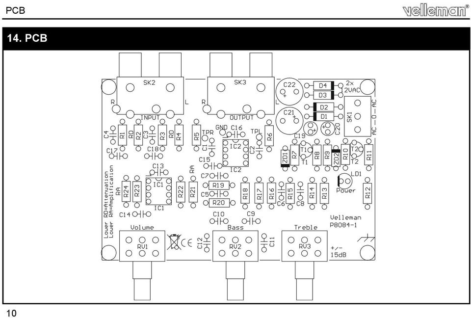
10 PCB 14. PCB 10
11 diagram 15. Schematic diagram AC 2 x 12V SK1 AC 0 D1 1N4007 D2 1N µ/25-35v C21 R7 R8 ZD1 9V1 T1 BC547 C19 +V +V Power LED R9 22K AC SCREW03 D3 1N4007 D4 1N µ/25-35v C22 R10 ZD2 9V1 R11 T2 C20 BC557 -V R12 10R -V LD1 LED5RL +V C5 50KLin RV3A C6 -V SK2A In L R3 C3 100p C18 1uF RV1A R4 50Klog 100K RD 3 2 IC1A C13 100nF 1 TL072 4n7 R14 3K3 R18 10K 4n7 C1 15p 2 3 C15 1 IC2A TL nF R5 10R SK3A Out L Lower RD for input devide R24 100K RA -V R23 RF C14 100nF R20 10K C9 47nF RV2A 50KLin C10 47nF R16 10K +V C16 100nF Amplification= (RF/RA)+1 C7 50Klin RV3B C8 4n7 4n7 SK2B In R R1 C4 100p R2 100K RD C17 1uF RV1B 50Klog IC1B TL072 C11 R13 3K3 R17 10K C12 C2 15p 6 5 IC2B TL072 7 R6 10R SK3B Out R Lower RD for input devide R22 R19 47nF 47nF R15 RF 10K RV2B 50KLin 10K R21 100K RA Amplification= (RF/RA)+1 11
+1 C7 50Klin RV3B C8 4n7 4n7 SK2B In R R1 C4 100p")
12 VELLEMAN NV Legen Heirweg 33, B-9890 GAVERE Belgium (Europe) Modifications and typographical errors reserved Velleman nv. - H8084IP (rev.3)

GUITAR PREAMPLIFIER WITH HEADPHONE OUTPUT K4102
 H4102IP-1 GUITAR PREAMPLIFIER WITH HEADPHONE OUTPUT K4102 Practice the guitar without disturbing others. Features & Specifications Features: An electric guitar cannot be connected to just any amplifier
Total solder points: 115 Difficulty level: beginner 1 2 3 4 5 advanced 4 CHANNEL RUNNING LIGHT K8032 ILLUSTRATED ASSEMBLY MANUAL
 Total solder points: 115 Difficulty level: beginner 1 2 3 4 5 advanced 4 CHANNEL RUNNING LIGHT K8032 Ideal for creating disco light effects, light speed adjustable. Suited for inductive loads. ILLUSTRATED
K2570 UNIVERSAL POWER SUPPLY 5-14DC / 1A. The easy way to power your ILLUSTRATED ASSEMBLY MANUAL
 Total solder points: 18 Difficulty level: beginner 1 2 3 4 5 advanced UNIVERSAL POWER SUPPLY 5-14DC / 1A K2570 The easy way to power your projects. ILLUSTRATED ASSEMBLY MANUAL H2570IP-1 Features & Specifications
200W DISCRETE POWER AMPLIFIER K8060
 H8060IP-1 200W DISCRETE POWER AMPLIFIER K8060 Ideal for active speaker system or subwoofer, guitar amp, home theatre systems, instrument amp, etc. Features & Specifications Specifications: Excellent value
DUAL ELECTRONIC DICE K3400
 DUAL ELECTRONIC DICE K3400 Cheating is no longer possible! ILLUSTRATED ASSEMBLY MANUAL H3400IP-1 VELLEMAN NV Legen Heirweg 33 9890 Gavere Belgium Europe www.velleman.be www.velleman-kit.com Features &
SYMMETRIC 1A POWER SUPPLY K8042
 SYMMETRIC 1A POWER SUPPLY K8042 Low cost universal symmetric power supply ILLUSTRATED ASSEMBLY MANUAL H8042IP-1 Features & Specifications Features low cost universal symmetric power supply just add a suitable
Total solder points: 18 Difficulty level: beginner 1 2 3 4 5 advanced UNIVERSAL POWER SUPPLY 5-14DC / 1A K2570 ILLUSTRATED ASSEMBLY MANUAL
 Total solder points: 18 Difficulty level: beginner 1 2 3 4 5 advanced UNIVERSAL POWER SUPPLY 5-14DC / 1A K2570 The easy way to power your projects. ILLUSTRATED ASSEMBLY MANUAL H2570IP-1 Features & Specifications
POCKET AUDIO GENERATOR K8065
 POCKET AUDIO GENERATOR K8065 Great little gadget for service repair, testing, education, etc... ILLUSTRATED ASSEMBLY MANUAL H8065IP-1 VELLEMAN NV Legen Heirweg 33 9890 Gavere Belgium Europe www.velleman.be
400W MONO/STEREO AMPLIFIER
 400W MONO/STEREO AMPLIFIER Universal, robust and compact are the words to describe this amplifier. Total solder points: 264 Difficulty level: beginner 1 2 3 4 5 advanced K4005B ILLUSTRATED ASSEMBLY MANUAL
Total solder points: 57 Difficulty level: beginner 1 2 3 4 5 advanced 3 TO 30VDC / 3A POWER SUPPLY K7203 ILLUSTRATED ASSEMBLY MANUAL H7203IP-1
 Total solder points: 57 Difficulty level: beginner 1 2 3 4 5 advanced 3 TO 30VDC / 3A POWER SUPPLY K7203 A power supply for all our kits, based on a stabilised DC voltage of 30V. ILLUSTRATED ASSEMBLY MANUAL
MAINS VOLTAGE DETECTOR K7101
 With this device wires can be very easily checked for mains voltage. H7101IP-1 MAINS VOLTAGE DETECTOR K7101 VELLEMAN NV Legen Heirweg 33 9890 Gavere Belgium Europe www.velleman.be www.velleman-kit.com
Total solder points: 67 Difficulty level: beginner 1 2 3. 4 5 advanced UNIVERSAL TEMPERATURE SENSOR K8067 ILLUSTRATED ASSEMBLY MANUAL
 Total solder points: 67 Difficulty level: beginner 1 2 3 4 5 advanced UNIVERSAL TEMPERATURE SENSOR K8067 Ideal for connection to computer interface boards (K8000, K8055, K8047,..) ILLUSTRATED ASSEMBLY
Total solder points: 147 Difficulty level: beginner 1 2 3 4 5 advanced VIDEO SIGNAL CLEANER K8036 ILLUSTRATED ASSEMBLY MANUAL
 Total solder points: 147 Difficulty level: beginner 1 2 3 4 5 advanced VIDEO SIGNAL CLEANER K8036 Digitally cleans the video signal of unwanted distortions and improves the picture quality. ILLUSTRATED
Total solder points: 205 Difficulty level: beginner 1 2 3 4 5 advanced UNIVERSAL BATTERY CHARGER / DISCHARGER K7300 ILLUSTRATED ASSEMBLY MANUAL
 Total solder points: 205 Difficulty level: beginner 1 2 3 4 5 advanced UNIVERSAL BATTERY CHARGER / DISCHARGER K7300 Automatic (dis)charging of both NiCd and NiMH batteries. ILLUSTRATED ASSEMBLY MANUAL
K4401 SOUND GENERATOR. them at the touch of a button. Specifications
 SOUND GENERATOR K4401 Sound effects, tunes, sirens... 10 of them at the touch of a button. Specifications Loudspeakers output : 8 ohm/1w Line output : 1VRms. Power supply : 8 10VDC (9v battery). Max. current
7-SEGMENT DIGITAL CLOCK
 57mm 7-SEGMENT DIGITAL CLOCK Large 57mm clock & temperature display with extra unique feature Total solder points: 263 Difficulty level: beginner 1 2 3 4 5 advanced K8089 ILLUSTRATED ASSEMBLY MANUAL H8089IP-1
Total solder points: 167 Difficulty level: beginner 1 2 3 4 5 advanced DMX CONTROLLED RELAY K8072 ILLUSTRATED ASSEMBLY MANUAL
 Total solder points: 167 Difficulty level: beginner 1 2 3 4 5 advanced DMX CONTROLLED RELAY K8072 Control a relay by means of the wellknown DMX512 protocol. ILLUSTRATED ASSEMBLY MANUAL H8072IP-1 Features
Total solder points: 129 Difficulty level: beginner 1 2 3 4 5 advanced LIQUID LEVEL CONTROLLER K2639 ILLUSTRATED ASSEMBLY MANUAL H2639IP-1
 Total solder points: 129 Difficulty level: beginner 1 2 3 4 5 advanced LIQUID LEVEL CONTROLLER K2639 Forgotten to turn off the tap, leaking washing machines,... Prevention is better than cure. So use this
15 Channel IR transmitter. Total solder points: 53 Difficulty level: beginner 1 2 3 4 5 advanced K8049 ILLUSTRATED ASSEMBLY MANUAL
 15 Channel IR transmitter Compatible with most Velleman IR receiver kits, 4 adresses allow the use of multiple receivers in one room. Total solder points: 53 Difficulty level: beginner 1 2 3 4 5 advanced
PC FUNCTION GENERATOR
 PC FUNCTION GENERATOR Create standard signal waves like e.g. sine, triangle and rectangle are available; other sine waves can be easily created with integrated software. Total solder points: 954 Difficulty
DIGITAL PC SCOPE. Total solder points: 625 Difficulty level: beginner 1 2 3 4 5 advanced K8031 ILLUSTRATED ASSEMBLY MANUAL
 DIGITAL PC SCOPE Digital storage oscilloscoop, using a computer and its monitor to display waveforms. All standard oscilloscope functions are available in the Windows program supplied. Total solder points:
K8068 BUS DIMMER FOR HOME MODULAR LIGHT SYSTEM ILLUSTRATED ASSEMBLY MANUAL H8068IP-1
 Total solder points: 74 Difficulty level: beginner 1 2 3 4 5 advanced BUS DIMMER FOR HOME MODULAR LIGHT SYSTEM K8068 PLUG - IN module for use with home modular lights system K8006. For electronic transformers!
K6002 TEMPERATURE CONTROLLER. Specifications
 Total solder points: 169 + 99 + 67 Difficulty level: beginner 1 2 3 4 5 advanced TEMPERATURE CONTROLLER K6002 Unlike a normal thermostat, this kit has two outputs, one for "high" alarm and one for "low"
Total solder points: 248 Difficulty level: beginner 1 2 3 4 5 advanced. 15 Channel infrared receiver K8050 ILLUSTRATED ASSEMBLY MANUAL
 Total solder points: 48 Difficulty level: beginner 4 5 advanced 5 Channel infrared receiver K8050 IR-Remote control transmitters allow you to control 5 opencollector contacts ILLUSTRATED ASSEMBLY MANUAL
K8025 VIDEO PATTERN GENERATOR. Check the picture quality of your monitor or TV, ideal for adjustment or troubleshooting.
 K8025 ILLUSTRATED ASSEMBLY MANUAL H8025IP 1 VIDEO PATTERN GENERATOR Check the picture quality of your monitor or TV, ideal for adjustment or troubleshooting. Forum Participate our Velleman Projects Forum
POWERBLOCK - POWER AMPLIFIER
 POWERBLOCK - POWER AMPLIFIER This amplifier is an ideal set-up for active speaker use. Total solder points: 383 Difficulty level: beginner 1 2 3 4 5 advanced K8081 ILLUSTRATED ASSEMBLY MANUAL H8081IP-1
Total solder points: 85 Difficulty level: beginner 1 2 3 4 5 advanced MULTIFUNCTION RELAY SWITCH K8015 ILLUSTRATED ASSEMBLY MANUAL H8015IP-2
 Total solder points: 85 Difficulty level: beginner 1 2 3 4 5 advanced MULTIFUNCTION RELAY SWITCH K8015 14 Different functions including timers, switching, flashing, interval, random switching,... ILLUSTRATED
The new Velleman Projects catalogue is now available. Download your copy here: www.vellemanprojects.eu
 The new Velleman Projects catalogue is now available. Download your copy here: www.vellemanprojects.eu Modifications and typographical errors reserved - Velleman nv. H8098 IP 2 (rev.1.0) Velleman NV, Legen
ELECTRONIC TRANSISTOR IGNITION FOR CARS K2543
 H2543IP 1 ELECTRONIC TRANSISTOR IGNITION FOR CARS K2543 Gives your car a better starting and smoother running. Suitbale for 12V and 6V systems. Features & Specifications Even the most sceptical one has
With the K8097 4-channel stepper motor card you can drive 4 stepper motors via USB, and monitor and assign actions if needed to 5 dry contacts
 K8097 K80977IP ILLUSTRATED LU TED ASSEMBLY SEMB MANUAL H8097IP - Channel USB stepper motor card With the K8097 -channel stepper motor card you can drive stepper motors via USB, and monitor and assign actions
100W SUBWOOFER KIT. Total solder points: 383 Difficulty level: beginner 1 2 3 4 5 advanced K8077 ILLUSTRATED ASSEMBLY MANUAL
 100W SUBWOOFER KIT Powerful bass from a small cabinet thanks to the dual speaker principle Total solder points: 383 Difficulty level: beginner 1 2 3 4 5 advanced K8077 ILLUSTRATED ASSEMBLY MANUAL H8077IP-1
Fan timer K8041. Features: Specifications :
 Total solder points: 101 Difficulty level: beginner 1 2 3 4 5 advanced Features: Fan timer K8041 Suitable for most types of ventilators Solid state switching with noise suppression Can be connected to
Kit 106. 50 Watt Audio Amplifier
 Kit 106 50 Watt Audio Amplifier T his kit is based on an amazing IC amplifier module from ST Electronics, the TDA7294 It is intended for use as a high quality audio class AB amplifier in hi-fi applications
3.5A SUPPRESSED DIMMER K8026
 Total solder points: 29 Difficulty level: beginner 1 2 3 4 5 3.5A SUPPRESSED DIMMER K8026 Dimmer for incandescent lightbulbs and collector motors Fuse protected AC power : 110-125 or 220-240VAC 50/60Hz
TRANSISTOR IGNITION K2543
 Total solder points: 38 Skill level : Beginner 1 2 3 4 5 Advanced HIGH-Q TRANSISTOR IGNITION K2543 Applications : Upgrade the existing ignition system of : Cars, motorcycles, mowers, outboards, Reduces
DUAL ELECTRONIC DICE K3400
 Total solder points: 198 Skill level : Beginner 1 2 3 4 5 Advanced DUAL ELECTRONIC DICE K3400 Features: Two independent dice Use a single or both dice at the same time Display auto shut-off saves battery
K8048 PIC PROGRAMMER AND EXPERIMENT BOARD. Specifications
 Total solder points: 274 Difficulty level: beginner 1 2 3 4 5 advanced PIC PROGRAMMER AND EXPERIMENT BOARD K8048 Suitable for programming Microchip Flash PIC TM microcontrollers. Basic programming knowledge
Dc to Pulse Width Modulator
 Total solder points: 82 Difficulty level: beginner 1 2 3 4 5 advanced Dc to Pulse Width Modulator Hardware: K8004 PWM range: 0 to 100% PWM frequency: 100 to 5000Hz adjustable Minimum PWM offset: 0 to 20%
Stereo valve power amplifier
 Stereo valve power amplifier For most of us a high power valve amplifier is unaffordable. This kit changes that, so that now everybody can enjoy that sublime "valve sound". Total solder points: 00 Difficulty
Assembly and User Guide
 1 Amp Adjustable Electronic Load 30V Max, 1 Amp, 20 Watts Powered by: 9V Battery Assembly and User Guide Pico Load is a convenient constant current load for testing batteries and power supplies. The digital
DC CONTROLLED DIMMER Manual
 Total solder points: 61 Skill level : Beginner 1 2 3 4 5 Advanced K8003 DC CONTROLLED DIMMER Manual This small but handy circuit is ideal for replacing an existing dimmer or switch, in order to be able
Total solder points: 202 Difficulty level: beginner 1 2 3 4 5 advanced. PIC programmer board K8076 ILLUSTRATED ASSEMBLY MANUAL
 Total solder points: 0 Difficulty level: beginner advanced PIC programmer board K0 This board can program a wide range of Microchip PIC microcontrollers ILLUSTRATED ASSEMBLY MANUAL H0IP- This device complies
Cumbria Designs T-1. SSB/CW Filter kit (4.9152MHz) User Manual
 User Manual") Cumbria Designs T-1 SSB/CW Filter kit (4.9152MHz) User Manual CONTENTS 1 INTRODUCTION 2 2 CIRCUIT DESCRIPTION 2 3 ASSEMBLY 2 4 TESTING 4 The Steading Stainton PENRITH Cumbria CA11 0ES UK 1 Introduction
Cumbria Designs T-1 SSB/CW Filter kit (4.9152MHz) User Manual CONTENTS 1 INTRODUCTION 2 2 CIRCUIT DESCRIPTION 2 3 ASSEMBLY 2 4 TESTING 4 The Steading Stainton PENRITH Cumbria CA11 0ES UK 1 Introduction
IMPORTANT SAFETY INSTRUCTIONS
 IMPORTANT SAFETY INSTRUCTIONS When using this electronic device, basic precautions should always be taken, including the following: 1. Read all instructions before using the product. 2. Do not use this
AUTOMATIC CALL RECORDER JAMECO PART NO. 2163735
 AUTOMATIC CALL RECORDER JAMECO PART NO. 2163735 Experience Level: Intermediate Time Required: 1-2 Hours This project automatically records phone calls. The program, along with the adapter records each
C220 PRELIMINARY TUBE PREAMPLIFIER SERVICE MANUAL. SERIAL NO. WS1001 And Above C220. Serial Number W S1001 And Above CONTENTS
 Performance Specifications... 2 Notes... 2 Rear Panel... 3 Section Location... 3 Block Diagram... 5-6 Interconnection Diagram... 7-8 Main Schematic and PCB... 9-18 C220 TUBE PREAMPLIFIER CONTENTS Display
Build A Video Switcher. Reprinted with permission from Electronics Now Magazine September 1997 issue
 Build A Video Switcher Reprinted with permission from Electronics Now Magazine September 1997 issue Copyright Gernsback Publications, Inc.,1997 BUILD A VIDEO SWITCHER FRANK MONTEGARI Watch several cameras
Assembly Instructions: Shortwave Radio Kit
 Assembly Instructions: Shortwave Radio Kit MTM Scientific, Inc P.O. Box 522 Clinton, MI 49236 U.S.A Introduction Fig 1: The assembled Shortwave Radio Kit The SHORTWAVE RADIO KIT (#SWRAD) from MTM Scientific
4 channel recorder / logger
 Total solder points: 159 Difficulty level: beginner 1 2 3 4 5 advanced 4 channel recorder / logger Hardware: USB connected and powered. Four DC coupled input channels. Input resistance 1Mohm. Maximum samples
Kit 27. 1W TDA7052 POWER AMPLIFIER
 Kit 27. 1W TDA7052 POWER AMPLIFIER This is a 1 watt mono amplifier Kit module using the TDA7052 from Philips. (Note, no suffix.) It is designed to be used as a building block in other projects where a
LOXONE 12 Channel Amplifier
 LOXONE 12 Channel Amplifier Item no.: 200110 Thank you for purchasing the Loxone Twelve Channel Amplifier. The versatility of the Amplifier makes it the perfect choice for almost every type of custom multi-room
Analog control unit for mobile robots
 Analog control unit for mobile robots Soldering kit for experimentation For Fischertechnik robots and others Most diverse functions Requires no programming Patented sensor technology Summary We are pleased
Assembly Notes. Disclaimer:
 Assembly Notes Before you start building your kit, please take time to read the manual in full at least once to enable you to fully understand the procedures and avoid any mistakes. The following notes
QUASAR ELECTRONICS KIT No. 1015 ELECTRONIC MOSQUITO REPELLER
 QUASAR ELECTRONICS KIT No. 1015 ELECTRONIC MOSQUITO REPELLER General Description This simple circuit can prove itself worth many times its value (which is very reasonable anyway) in getting rid of mosquitoes
LM1036 Dual DC Operated Tone/Volume/Balance Circuit
 LM1036 Dual DC Operated Tone/Volume/Balance Circuit General Description The LM1036 is a DC controlled tone (bass/treble), volume and balance circuit for stereo applications in car radio, TV and audio systems.
ECEN 1400, Introduction to Analog and Digital Electronics
 ECEN 1400, Introduction to Analog and Digital Electronics Lab 4: Power supply 1 INTRODUCTION This lab will span two lab periods. In this lab, you will create the power supply that transforms the AC wall
2 X 250Watt Class D Audio Amplifier Board IRS2092 User s Guide
 2 X 250Watt Class D Audio Amplifier Board IRS2092 User s Guide 2004-2013 Sure Electronics Inc. AA-AB32291_Ver1.0 2 X 250Watt Class D Audio Amplifier Board IR2092 Note: Please read this manual carefully
SUPER SNOOPER BIG EAR
 AA-1D Super Snooper Big Ear SPECIFICATIONS Operates on 5 to 9v DC Will drive a small speaker Provides up to 1 watt of audio power Distortion > 0.2% Voltage Gain up to 46 db Size: 1 x 1.95 Rainbowkits.com
Electronics. Discrete assembly of an operational amplifier as a transistor circuit. LD Physics Leaflets P4.2.1.1
 Electronics Operational Amplifier Internal design of an operational amplifier LD Physics Leaflets Discrete assembly of an operational amplifier as a transistor circuit P4.2.1.1 Objects of the experiment
Joule Thief 3.0 Kit. June 2012, Rev 1 1 http://www.easternvoltageresearch.com Joule Thief 3.0
 Kit Instruction Manual Eastern Voltage Research, LLC June 2012, Rev 1 1 http://www.easternvoltageresearch.com HIGH BRIGHTNESS LED THIS KIT USES A 1W CREE, HIGH BRIGHTNESS LED. DO NOT STARE AT THIS (OR
MODEL 2202IQ (1991-MSRP $549.00)
") F O R T H E L O V E O F M U S I C F O R T H E L O V E O F M U S I C MODEL 2202IQ (1991-MSRP $549.00) OWNER'S MANUAL AND INSTALLATION GUIDE INTRODUCTION Congratulations on your decision to purchase a LINEAR
F O R T H E L O V E O F M U S I C F O R T H E L O V E O F M U S I C MODEL 2202IQ (1991-MSRP $549.00) OWNER'S MANUAL AND INSTALLATION GUIDE INTRODUCTION Congratulations on your decision to purchase a LINEAR
phonostage RIP YOUR VINYL TO BITS, WITH A USB Design
 RIP YOUR VINYL TO BITS, WITH A USB phonostage So what do you do with that collection of LPs you have? Sure, they sound great and are fun to listen to, but let s face it, they re not exactly portable. Wouldn
The Radio-Kits Digital SWR meter kit Construction and user manual
 The Radio-Kits Digital SWR meter kit Construction and user manual Author - Steve Drury G6ALU List of contents Section Page no. 1. Features and specifications 2 2. Introduction 2. Construction 4. General
TEACHING RESOURCES SCHEMES OF WORK DEVELOPING A SPECIFICATION COMPONENT FACTSHEETS HOW TO SOLDER GUIDE GET IN TUNE WITH THIS FM RADIO KIT. Version 2.
 TEACHING RESOURCES SCHEMES OF WORK DEVELOPING A SPECIFICATION COMPONENT FACTSHEETS HOW TO SOLDER GUIDE GET IN TUNE WITH THIS FM RADIO KIT Version 2.0 Index of Sheets TEACHING RESOURCES Index of Sheets
AutoRanging Digital MultiMeter
 Owner's Manual AutoRanging Digital MultiMeter Model No. 82139 CAUTION: Read, understand and follow Safety Rules and Operating Instructions in this manual before using this product. Safety Operation Maintenance
The RSGB Centenary Receiver Project Construction Manual
 The RSGB Centenary Receiver Project Construction Manual Page 1 of 12 Introduction This project is intended for those new to radio construction. It is a fairly simple receiver for the 14MHz (20m) amateur
Users Guide for the Non-Inverted LM3886 Kit
 Users Guide for the Non-Inverted LM3886 Kit Chipamp.com 1 (14) Users Guide for the Non-Inverted LM3886 Kit 1 INTRODUCTION... 2 1.1 TERMINOLOGY USED IN THIS DOCUMENT... 2 1.2 AMPLIFIER BOARD SCHEMATIC...
1218-75 Watt Audiophile Audio Amplifier
 Description Quasar kit No.1218 is part of a new line of constructions which combined form a full stereo system. The line consists of the following KITS Quasar kit No.1214 6 inputs stereo selector Quasar
DDS VFO CONSTRUCTION MANUAL. DDS VFO Construction Manual Issue 1 Page 1
 DDS VFO CONSTRUCTION MANUAL DDS VFO Construction Manual Issue 1 Page 1 Important Please read before starting assembly STATIC PRECAUTION The DDS VFO kit contains the following components which can be damaged
unit:mm 3022A-DIP12F 0.5 0.81 2.54
 Ordering number:enn1718b Monolithic Linear IC LA4550 2-Channel AF Power Amplifier for Radio, Tape Recorder Use Features Low quiescent current. On-chip 2 channels permitting use in stereo and bridge amplifier
step 1 Unpack the lunchbox And check whether you have got all the components~ If you have questions please contact us at: info@unitunlikely.
 step 1 Unpack the lunchbox And check whether you have got all the components~ If you have questions please contact us at: info@unitunlikely.com This part is called the PCB (printed circuit board). All
Operation Manual for Users
 Operation Manual for Users Model No.: FLTAMFMRCD!!!!!!!!!! ATTENTION!!!!!!!!!! THE RESET BUTTON MUST BE PRESSED TO ENSURE PROPER OPERATION. SEE INSTRUCTION MANUAL Table of Contents Table of Contents ---------------------------------------------------------------------------------------------
Knight Audio Technologies Ltd. Deacy - Style Amplifier Kit Build Instructions
 Knight Audio Technologies Ltd Deacy - Style Amplifier Kit Build Instructions Introduction Firstly, thank you for purchasing this amplifier kit. We have designed this amplifier based on the Mullard 1960
Electronics and Soldering Notes
 Electronics and Soldering Notes The Tools You ll Need While there are literally one hundred tools for soldering, testing, and fixing electronic circuits, you only need a few to make robot. These tools
DATA SHEET. TDA8560Q 2 40 W/2 Ω stereo BTL car radio power amplifier with diagnostic facility INTEGRATED CIRCUITS. 1996 Jan 08
 INTEGRATED CIRCUITS DATA SHEET power amplifier with diagnostic facility Supersedes data of March 1994 File under Integrated Circuits, IC01 1996 Jan 08 FEATURES Requires very few external components High
TELEPHONE LINE ANALYZER KIT
 TELEPHONE LINE ANALYZER KIT MODEL TT-400K Assembly and Instruction Manual Elenco Electronics, Inc. Copyright 1994 Elenco Electronics, Inc. Revised 2001 REV-C 753253 INTRODUCTION Are you planning to install
DATA SHEET. TDA1518BQ 24 W BTL or 2 x 12 watt stereo car radio power amplifier INTEGRATED CIRCUITS
 INTEGRATED CIRCUITS DATA SHEET File under Integrated Circuits, IC01 July 1994 GENERAL DESCRIPTION The is an integrated class-b output amplifier in a 13-lead single-in-line (SIL) plastic power package.
!Operation:!1. Connect an external power source to J1 (+ and - IN terminals). The
. The") The CB500 Electronic Circuit Breaker is an resettable circuit breaker (fuse) that disconnects power when the trip setting is exceeded. There are 4 trip settings that can easily be changed and set during
The CB500 Electronic Circuit Breaker is an resettable circuit breaker (fuse) that disconnects power when the trip setting is exceeded. There are 4 trip settings that can easily be changed and set during
6 X 100Watt Class-D Audio Amplifier Board- TDA7498 User s Guide
 6 X 100Watt Class-D Audio Amplifier Board- TDA7498 User s Guide 2004-2012 Sure Electronics Inc. AA-AB34181_Ver1.0 6 X 100Watt Class-D Audio Amplifier Board TDA7498 To keep the product in a best working
Build a Voltage and Current Peak Detector
 ax You Can DIY! Build a Voltage and Current Peak Detector Here is a simple portable device that can help answer the question about peak voltage and peak current requirements and whether or not your power
Functioning. Layout Diagram. Technical Data. Connection Diagram. 2.4.3. Fixing the Battery Clip. 2.4.4. Inserting the Panel for the Slide Switch
 Sales Germany and other EU Countries Naturschutzzentrum Westlicher Hegau Erwin-Dietrich-Str. 3 D-78244 Gottmadingen Phone: 07731/977 103 Fax: 07731/977 104 e-mail: nsz.hegau@bund.net SSF - Bat Detector
GLOLAB Two Wire Stepper Motor Positioner
 Introduction A simple and inexpensive way to remotely rotate a display or object is with a positioner that uses a stepper motor to rotate it. The motor is driven by a circuit mounted near the motor and
Active Speaker System LX523 AUDAC PROFESSIONAL AUDIO EQUIPMENT. Active Speaker System with remote input LX523. User Manual & Installation Guide
 Active Speaker System LX523 AUDAC PROFESSIONAL AUDIO EQUIPMENT Active Speaker System with remote input LX523 User Manual & Installation Guide AUDAC PROFESSIONAL AUDIO EQUIPMENT User Manual & Installation
unit : mm With heat sink (see Pd Ta characteristics)
") Ordering number: EN1321E Monolithic Linear IC LA4261 3.5 W 2-Channel AF Power Amplifier for Home Stereos and Music Centers Features. Minimum number of external parts required (No input capacitor, bootstrap
Ordering number: EN1321E Monolithic Linear IC LA4261 3.5 W 2-Channel AF Power Amplifier for Home Stereos and Music Centers Features. Minimum number of external parts required (No input capacitor, bootstrap
3 Slot Payphone Controller
 5A2 3 Slot Payphone Controller The 3 Slot Payphone -- Part of American History Building a Coin Relay Controller Version S1BX Instruction Manual and Safety Precautions It is very important that for your
1 All safety instructions, warnings and operating instructions must be read first.
 ONYX USER MANUAL 2 Dateq ONYX Manual Safety instructions EN Safety instructions 1 All safety instructions, warnings and operating instructions must be read first. 2 All warnings on the equipment must be
TOA 900 SERIES II MIXER POWER AMPLIFIER
 Operating Instructions TOA 900 SERIES II MIXER POWER AMPLIFIER A-903MK2 A-906MK2 A-912MK2 TO REDUCE THE RISK OF ELECTRICAL SHOCK, DO NOT REMOVE COVER. NO USER SERVICEABLE PARTS INSIDE. REFER SERVICING
User's Guide. True RMS Industrial Multimeter
 User's Guide 97650 True RMS Industrial Multimeter Ω C ã F ã 10A V µ 10A V ã ã ma A Introduction This meter measures AC/DC Voltage, AC/DC Current, Resistance, Capacitance, Frequency (electrical & electronic),
K8055 Specifications:
 Total solder points: 159 Difficulty level: beginner 1 2 3 4 5 advanced USB Experiment interface board K8055 Specifications: 5 Digital inputs (0= ground, 1= open). On board test buttons provided. 2 Analog
GLOLAB Universal Telephone Hold
 GLOLAB Universal Telephone Hold 1 UNIVERSAL HOLD CIRCUIT If you have touch tone telephone service, you can now put a call on hold from any phone in the house, even from cordless phones and phones without
LIGHT COMPUTER K5201
 Total solder points: 240 Skill level : Beginner 1 2 3 4 5 Advanced LIGHT COMPUTER K5201 Features: Sixteen different patterns and 7 outputs provide a unique light show Easy pattern selection with rotary
INSTRUCTION MANUAL PLEASE READ ALL THE INSTRUCTIONS COMPLETELY BEFORE USE AND SAVE THIS MANUAL FOR FUTURE REFERENCE
 INSTRUCTION MANUAL PLEASE READ ALL THE INSTRUCTIONS COMPLETELY BEFORE USE Ver. 2.0 AND SAVE THIS MANUAL FOR FUTURE REFERENCE Table of Contents Unpacking... 3 About the CCRadio-EP... 4 Quick Start Guide...
Contents. Safety Warnings... 1
 Contents Safety Warnings... 1 Unpacking the GQ600... 1 Introduction... 2 GQ600 Filter Characteristics... 2 1/3 Octave Centre Frequencies... 4 Front Panel Functions... 5 Rear Panel Functions... 6 Specifications...
LM386 Low Voltage Audio Power Amplifier
 Low Voltage Audio Power Amplifier General Description The LM386 is a power amplifier designed for use in low voltage consumer applications. The gain is internally set to 20 to keep external part count
DET Practical Electronics (Intermediate 1)
") DET Practical Electronics (Intermediate 1) 731 August 2000 HIGHER STILL DET Practical Electronics (Intermediate 1) Support Materials CONTENTS Section 1 Learning about Resistors Section 2 Learning about
DET Practical Electronics (Intermediate 1) 731 August 2000 HIGHER STILL DET Practical Electronics (Intermediate 1) Support Materials CONTENTS Section 1 Learning about Resistors Section 2 Learning about
************* OWNER'S MANUAL BAMF800/2 BAMF1250/2 BAMF1800/2 BAMF2200/2 BAMF2600/2 BAMF1200/4 BAMF1600/4 BAMF2000/1D BAMF4000/1D BAMF5500/1D
 ************* OWNER'S MANUAL BAMF800/2 BAMF1250/2 BAMF1800/2 BAMF2200/2 BAMF2600/2 BAMF1200/4 BAMF1600/4 BAMF2000/1D BAMF4000/1D BAMF5500/1D INTRODUCTION Power Acoustik amplifiers provide high-performance
OWNER'S MANUAL HIGH PERFORMANCE AMPLIFIERS
 OWNER'S MANUAL HIGH PERFORMANCE AMPLIFIERS B2 has through years of dedication introduced our line of Ref 0.5 & Anno amplifiers. The B2 line up are made to fullfil our philosophy for amplifiers; A variety
Bose Model 1801/1800 Power Amplifier
 SUPPLEMENT Bose Model 1801/1800 Power Amplifier Q4, part number 102428 and Q5, part number 102429 are no longer available with the lead length needed for soldering to the PCB. Use the part numbers listed
Modifying the Yaesu FT-847 External 22.625 MHz Reference Input
 Modifying the Yaesu FT-847 External 22.625 MHz Reference Input David Smith VK3HZ Introduction This document describes the modification of an FT-847 to allow an external 22.625 MHz Reference oscillator
K8022. Passive Preamp with RF remote control
 Total solder points: 220+ 65 Difficulty level: beginner 1 2 3 4 5 advanced Passive Preamp with RF remote control Two stereo line level RCA inputs One stereo RCA output to power amp Motor controlled volume