GLOLAB Universal Telephone Hold
|
|
|
- Osborn McBride
- 7 years ago
- Views:
Transcription
1 GLOLAB Universal Telephone Hold 1 UNIVERSAL HOLD CIRCUIT If you have touch tone telephone service, you can now put a call on hold from any phone in the house, even from cordless phones and phones without a hold button by plugging this device into any telephone jack, anywhere in the house. Just one of these UNIVERSAL HOLD circuits adds the call hold feature to every phone that has a keypad with a # (pound) key. To put a call on hold, you press the # key and hang the phone up. The # key function remains activated for five seconds after the key is pressed and released so you can hang up phones that have a keypad in the handset. WHAT IT DOES The UNIVERSAL HOLD circuit detects the dual tone, multi frequency (DTMF) tone that is generated when the # key is pressed and then activates a circuit that partially loads the telephone line so that the central office thinks a phone is still off hook even after it is hung up. When any phone is again picked up, the hold function is canceled. HOW IT WORKS Figure 1 shows the schematic diagram of the UNIVERSAL HOLD circuit. The telephone line is connected to the hold components through bridge rectifier BR so the input is not polarity sensitive and the input lines may be connected either way. BR always connects the positive side of the line to zener diode D2 and the negative side of the line to IC2. If L1 is positive, current flows into the circuit through bridge diode A and back out through diode D into L2. If L2 is positive, current flows in through diode C and out through diode B into L1. The telephone line also connects to tone decoder IC4 through C4 and T1. Optoisolator IC1 contains a silicon controlled rectifier (SCR) having a characteristic that makes it continue to conduct current, or latch on, once turned on by current flowing through an optically coupled LED within the IC. The SCR conduction continues even after the LED current is removed, providing enough anode current is available to sustain it. When the SCR anode voltage is removed and conduction stops, it will not resume when voltage is re-applied until again triggered by LED current. This characteristic makes the SCR optoisolator ideal for a line hold application. When all phones are hung up (on-hook) the voltage across the telephone line is about 48 volts. When a phone is picked up (off-hook) it places a load on the line and a current of about 20 milliamps flows through the phone which causes the line voltage to drop to about 3 to 8 volts, depending on the telephone unit. Current also flows through circuits in the central office, indicating that the phone has been picked up. A call is put on hold when all phones are hung up and the SCR in IC1 is triggered on by circuits driving its LED (we ll tell you more about this later). When The SCR conducts, current flows through BR, D2, D1, IC1, IC2 and back through BR, placing a load on the line that keeps the central office circuits active. A 15 volt drop across D2, a 2 volt drop across D1, a 1.5 volt drop across the LED in IC2 and about a 1.5 volt drop across the diodes in BR results in the normal 48 volt open circuit line voltage across L1, L2 being clamped to about 20 volts which allows line current to flow but is a higher voltage than when a telephone loads the line. Now when a phone is picked up and the line voltage drops to about 8 volts or less, there is no longer enough voltage to produce conduction through D2, D1 IC1, IC2 and BR and the hold function is canceled. LED D1 is provided to indicate that a call is on hold. The telephone line also connects through C4 and transformer T1 to capacitor C8 which couples the DTMF signal to the input of IC4, a Motorola MC or Harris CD22204 dual tone, multi frequency tone decoder integrated circuit used to detect the # key tone. The 3.57 Mhz crystal XTAL

2 GLOLAB Universal Telephone Hold generates a clock required by the decoder. Zener diode D6 clamps its input to prevent damage from transients. The decoder has four outputs that produce a hexadecimal code corresponding to the tones it 2 receives when a key is pressed as shown in table 1. When these outputs are further decoded, the 1 or 0 status of all four outputs usually must be considered to get a unique hexadecimal number for each DTMF tone. Notice, however, that a 1 occurs simultaneously in both the pins 13 and 14 outputs only when the # key is pressed. This makes using the outputs easier since only two hexadecimal bits must be considered to decode the # key. The binary decoding is done by a logical AND circuit consisting of two diodes, D4 and D5 whose cathode terminals must both be at an up level or logical 1 for their anodes, which are connected together, to be pulled up by R5. This up level discharges C1 through R4 into the positive supply. When the # key is released the DTMF signal stops, pins 13 and 14 go down again and a down level pulse is produced by time constant C1, R4 at the pin 2 trigger input of timer IC3. Since the IC3 trigger input must receive a negative transition to start a timing cycle, the cycle does not start until the # key is released. When the timing cycle starts, IC3 output pin 3 goes up for five seconds and drives current through R3 into the LED within IC1 which places its SCR in a potentially conducting state where it needs only to have sufficient voltage applied to its anode terminal to make it heavily conduct and latch on, a condition that occurs when the phone is hung up. The five second output from IC3 keeps IC1 LED current flowing long enough to hang up the phone and have the required anode voltage applied to maintain conduction. The time duration is controlled by R7 and C7 and may be altered by changing the value of R7. IC2 is an optoisolator with a transistor output. After the # key is pressed and the phone is hung up, telephone line current flowing through the led in IC2 turns its transistor on which resets timer IC3 and terminates its timing cycle. This reset function removes current from the LED in IC1 and allows a hold to be canceled immediately after initiating it without having to wait for the five second cycle to complete. The transistor within IC2 also performs a power-on reset by having its base coupled through C5 to the positive supply. When power is turned off C5 discharges through D3. Power is supplied by a 12 volt DC wall transformer and by IC5, a 78L05 5 volt regulator, and is filtered by C2 and C3. The power supply, DTMF decoder and timing circuits are isolated from the telephone line by the optoisolators and transformer T1. TESTING Connect the hold circuit to the telephone line and plug the wall transformer into an AC outlet. Pick a phone up, press the # key and hang it up within five seconds. D1 should light. Pick a phone up and D1 should go out. Press the # key, wait about eight seconds and hang the phone up. D1 should not light. OPERATION The five second timing cycle that starts after the # key is released gives ample time to hang up a phone with a keypad on the handset. If the keypad is on the telephone base the # key can be pressed while the phone is being hung up. If the # key is pressed for reasons other than to place a call on hold, such as to signal the end of a number entry after using a fax back service, the timing cycle will end after five seconds and will probably not be active when the phone is hung up, but to be sure that the line is not on hold after using the # key just pick the phone up and hang up again.

3

4
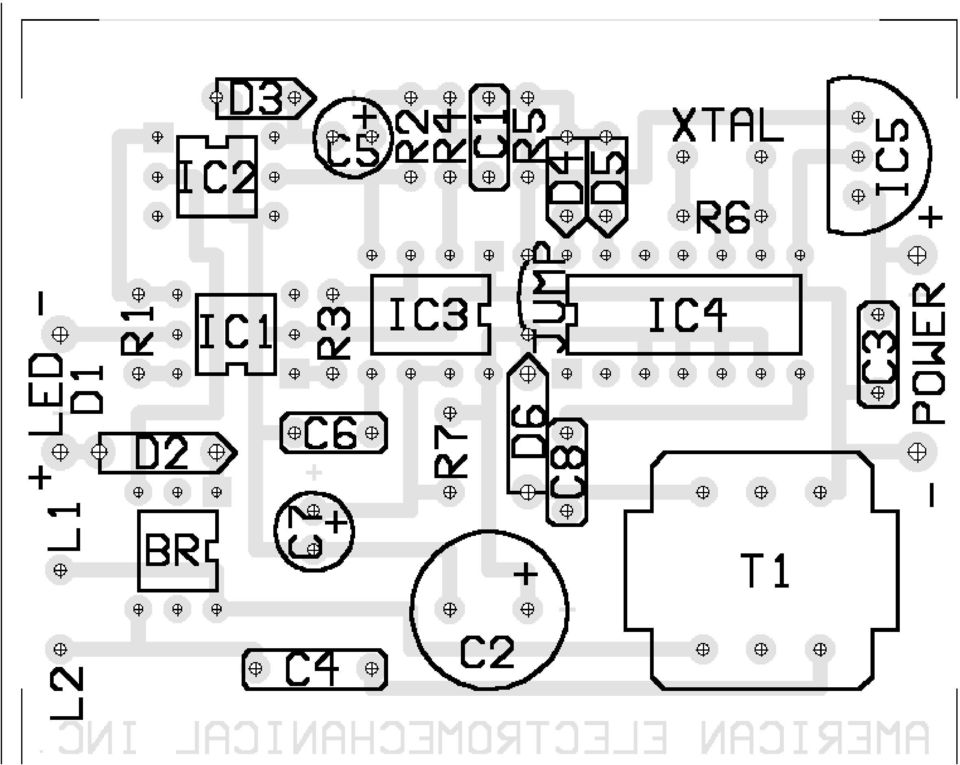
5 HEX DATA OUT CODE D8 D4 D2 D1 KEY IC PIN 13 IC PIN 14 IC PIN 1 IC PIN * # TABLE 1 BOARD IS HELD IN PLACE BY BOTTOM COVER ASSEMBLED UNIT TOP VIEW OF BOARD SIDE VIEW OF BOARD note LED mounted on right side

6 UNIVERSAL HOLD PARTS LIST R1, R4-56K 1/8 watt 5 % Digi-Key R2, R5-10K 1/8 watt 5% Digi-key R K 1/8 watt 5% Digi-Key R6, R7-1 MEG 1/8 watt 5% Digi-Key C1, C3 -.1 MFD 50 volt metalized film Digi-Key P4525 C MFD 16 volt electrolytic Digi-Key P6231 C4.1 MFD 250 volt polyester Digi-Key EF2104 C5-1 MFD 50 volt electrolytic Digi-Key P6260 C6, C MFD 50 volt metalized film Digi-Key P4513 C7-4.7 MFD 35 volt electrolytic Digi-Key P6247 D1 - light emitting diode Digi-Key LT1083 D2-1N volt 1 watt zener diode Jameco D3, D4, D5-1N914 silicon diode D6-1N volt 1 watt zener diode BR - DF04 1 AMP 400 volt DIP bridge rectifier IC1 - H11C1 SCR optoisolator Jameco IC2-4N28 transistor optoisolator Jameco IC3-555 timer IC4 - MC or CD22204 DTMF decoder or Circuit Specialists IC5-78L05 voltage regulator XTAL MHZ crystal Hosfelt T1-600 OHM primary, 600 OHM secondary transformer Jameco IC sockets - 3 six pin, 1 eight pin, 1 fourteen pin Digi-Key XFMR - 12 volt DC 100 MA wall transformer Hosfelt foot telephone wire with RJ11 plug plastic box - 2 X 3 X 1 Jameco two 4" cable ties Digi-Key printed circuit board American Electromechanical

7 UNIVERSAL HOLD ASSEMBLY INSTRUCTIONS 1. Insert and solder a bare jumper wire in the holes between IC3 and IC4 as shown in figure 2. A piece of lead from a resistor or capacitor may be used as a jumper. 2. Bend the resistor leads close to the resistor body. Insert and solder all resistors. 3. Bend diode D3, D4 and D5 leads close to the diode body. Insert and solder D3, D4 and D5 with the cathode band in the direction shown in figure Bend D2 and D6 leads. These leads are heavy and should be bent carefully if glass diodes are supplied. Insert and solder D2 and D6 with the cathode band in the direction shown in figure Insert and solder all.1 mfd and.01 mfd capacitors. 6. Insert and solder each IC socket with its alignment notch facing as shown in figure Insert and solder crystal XTAL. 8. Insert and solder voltage regulator 78L05 with its flat side facing XTAL. 9. Insert and solder electrolytic capacitors C2, C5 and C7 with their long positive leads connected to + as shown in figure 2. A + symbol is also marked on the PC board to indicate polarity. 10. Insert and solder transformer T1. Both the primary and secondary of T1 are 600 ohms so it may be connected in either direction. 11. Insert and solder LED D1 with its long positive lead connected to + as shown in figure 2. Leave the leads long and bend them in an S shape as shown in figure 3 to adjust the height of the LED so it fits through the hole in the box. 12. Insert and solder the wall transformer leads. The positive lead has a white tracer stripe and should be connected to the positive terminal as shown in figure 2. A + symbol is also marked on the board to indicate polarity. 13. Strip about ¼ inch of insulation from the red and green wires in the telephone cable. Tin the wires to make insertion easier. Insert and solder these wires in either direction since the circuit is not polarity sensitive. The telephone cable has 4 wires but only the red and green are used. 14. Place a cable tie around the telephone cable and another around the power cable. Adjust their position to leave sufficient slack in the cables to prevent strain on the PC board. Pull the ties very tight so they cannot slide on the wires and cut the tails off. 15. Plug each IC into its socket with the pin 1 indicator in the same direction as the socket notch. 16. Place the PC board in the box with the cable ties inside and the LED going through the hole. Screw the cover in place.

Glolab Talking Phone Dial Monitor
 Introduction The detects the tones generated when numbers are dialed on your touch tone telephone and speaks the numbers that were dialed. This verifies that you dialed the correct number and is especially
GLOLAB Two Wire Stepper Motor Positioner
 Introduction A simple and inexpensive way to remotely rotate a display or object is with a positioner that uses a stepper motor to rotate it. The motor is driven by a circuit mounted near the motor and
Build A Video Switcher. Reprinted with permission from Electronics Now Magazine September 1997 issue
 Build A Video Switcher Reprinted with permission from Electronics Now Magazine September 1997 issue Copyright Gernsback Publications, Inc.,1997 BUILD A VIDEO SWITCHER FRANK MONTEGARI Watch several cameras
Objectives: Part 1: Build a simple power supply. CS99S Laboratory 1
 CS99S Laboratory 1 Objectives: 1. Become familiar with the breadboard 2. Build a logic power supply 3. Use switches to make 1s and 0s 4. Use LEDs to observe 1s and 0s 5. Make a simple oscillator 6. Use
ECEN 1400, Introduction to Analog and Digital Electronics
 ECEN 1400, Introduction to Analog and Digital Electronics Lab 4: Power supply 1 INTRODUCTION This lab will span two lab periods. In this lab, you will create the power supply that transforms the AC wall
3 Slot Payphone Controller
 5A2 3 Slot Payphone Controller The 3 Slot Payphone -- Part of American History Building a Coin Relay Controller Version S1BX Instruction Manual and Safety Precautions It is very important that for your
Kit 106. 50 Watt Audio Amplifier
 Kit 106 50 Watt Audio Amplifier T his kit is based on an amazing IC amplifier module from ST Electronics, the TDA7294 It is intended for use as a high quality audio class AB amplifier in hi-fi applications
PolyBot Board. User's Guide V1.11 9/20/08
 PolyBot Board User's Guide V1.11 9/20/08 PolyBot Board v1.1 16 pin LCD connector 4-pin SPI port (can be used as digital I/O) 10 Analog inputs +5V GND GND JP_PWR 3-pin logic power jumper (short top 2 pins
WHO ANSWERED FIRST? FIND OUT WITH THIS QUIZ BUZZER KIT
 WHO ANSWERED FIRST? FIND OUT WITH THIS QUIZ BUZZER KIT BUILD INSTRUCTIONS Before you put any components in the board or pick up the soldering iron, just take a look at the Printed Circuit Board (PCB).
Joule Thief 3.0 Kit. June 2012, Rev 1 1 http://www.easternvoltageresearch.com Joule Thief 3.0
 Kit Instruction Manual Eastern Voltage Research, LLC June 2012, Rev 1 1 http://www.easternvoltageresearch.com HIGH BRIGHTNESS LED THIS KIT USES A 1W CREE, HIGH BRIGHTNESS LED. DO NOT STARE AT THIS (OR
Electronics and Soldering Notes
 Electronics and Soldering Notes The Tools You ll Need While there are literally one hundred tools for soldering, testing, and fixing electronic circuits, you only need a few to make robot. These tools
POWER SUPPLY MODEL XP-15. Instruction Manual ELENCO
 POWER SUPPLY MODEL XP-15 Instruction Manual ELENCO Copyright 2013 by Elenco Electronics, Inc. REV-A 753020 All rights reserved. No part of this book shall be reproduced by any means; electronic, photocopying,
Assembly and User Guide
 1 Amp Adjustable Electronic Load 30V Max, 1 Amp, 20 Watts Powered by: 9V Battery Assembly and User Guide Pico Load is a convenient constant current load for testing batteries and power supplies. The digital
DIRECTION SENSING INFRARED MOTION DETECTOR MANUAL
 DIRECTION SENSING INFRARED MOTION DETECTOR MANUAL GLDIR MOTION DETECTOR GLOLAB CORPORATION Glolab does not offer a kit of parts for this project. We sell the PIR325 pyroelectric infrared sensor and FL65
THE MclNTOSH MC 2100 SOLID STATE STEREO POWER AMPLIFIER
 THE MclNTOSH MC 2100 SOLID STATE STEREO POWER AMPLIFIER Price $1.25 Your MC 2100 stereo amplifier will give you many years of pleasant and satisfactory performance. If you have any questions concerning
Martin County Amateur Radio Association. Nightfire Kits 1 LED Torch Kit 270016. Contents. Description
 Nightfire Kits 1 LED Torch Kit 270016 1 Contents Nightfire Kits LED Torch Kit 270016... 1 Description... 1 Safety and Assembly of the kit... 6 Required and Useful Tools... 7 Assembly... 8 Checkout and
TELEPHONE LINE ANALYZER KIT
 TELEPHONE LINE ANALYZER KIT MODEL TT-400K Assembly and Instruction Manual Elenco Electronics, Inc. Copyright 1994 Elenco Electronics, Inc. Revised 2001 REV-C 753253 INTRODUCTION Are you planning to install
Type SA-1 Generator Differential Relay
 ABB Automation Inc. Substation Automation and Protection Division Coral Springs, FL 33065 Instruction Leaflet 41-348.11C Effective: November 1999 Supersedes I.L. 41-348.11B, Dated August 1986 ( ) Denotes
Optical Sensor Interface for AFX Digital LED Timer/Counter by George Warner, Jan. 2003 warnergt@ptd.net
 Optical Sensor Interface for AFX Digital LED Timer/Counter by George Warner, Jan. 200 warnergt@ptd.net Abstract This paper presents a design for an optical sensor interface to an AFX Digital LED Timer/Counter.
Odyssey of the Mind Technology Fair. Simple Electronics
 Simple Electronics 1. Terms volts, amps, ohms, watts, positive, negative, AC, DC 2. Matching voltages a. Series vs. parallel 3. Battery capacity 4. Simple electronic circuit light bulb 5. Chose the right
INFRARED MOTION DETECTOR MANUAL
 INFRARED MOTION DETECTOR MANUAL GLMDA MOTION DETECTOR KIT GLMDA MOTION DETECTOR MODULE GLOLAB CORPORATION Thank you for buying our GLMDA Motion Detector kit or Module. The goal of Glolab is to produce
TEECES DOME LIGHTING SYSTEMS
 This lighting system was designed by John V (Teeces) to be a simple, customizable, expandable and affordable solution for dome lighting. An Arduino micro-controller is used to tell LED driver chips which
!Operation:!1. Connect an external power source to J1 (+ and - IN terminals). The
. The") The CB500 Electronic Circuit Breaker is an resettable circuit breaker (fuse) that disconnects power when the trip setting is exceeded. There are 4 trip settings that can easily be changed and set during
The CB500 Electronic Circuit Breaker is an resettable circuit breaker (fuse) that disconnects power when the trip setting is exceeded. There are 4 trip settings that can easily be changed and set during
BMD16N-SD. version 1.2
 BMD16NSD version 1.2 Feedback decoder with 16 contacts with integrated current detection for the S88bus Compatible with a.o. Märklin Digital, Uhlenbrock Intellibox, Fleischmann TwinCenter and LDT HSI88
ARDUINO SEVERINO SERIAL SINGLE SIDED VERSION 3 S3v3 (REVISION 2) USER MANUAL
 USER MANUAL") ARDUINO SEVERINO SERIAL SINGLE SIDED VERSION 3 S3v3 (REVISION 2) USER MANUAL X1: DE-9 serial connector Used to connect computer (or other devices) using RS-232 standard. Needs a serial cable, with at least
ARDUINO SEVERINO SERIAL SINGLE SIDED VERSION 3 S3v3 (REVISION 2) USER MANUAL X1: DE-9 serial connector Used to connect computer (or other devices) using RS-232 standard. Needs a serial cable, with at least
7-SEGMENT DIGITAL CLOCK
 57mm 7-SEGMENT DIGITAL CLOCK Large 57mm clock & temperature display with extra unique feature Total solder points: 263 Difficulty level: beginner 1 2 3 4 5 advanced K8089 ILLUSTRATED ASSEMBLY MANUAL H8089IP-1
Design Project: Power inverter
 Design Project: Power inverter This worksheet and all related files are licensed under the Creative Commons Attribution License, version 1.0. To view a copy of this license, visit http://creativecommons.org/licenses/by/1.0/,
step 1 Unpack the lunchbox And check whether you have got all the components~ If you have questions please contact us at: info@unitunlikely.
 step 1 Unpack the lunchbox And check whether you have got all the components~ If you have questions please contact us at: info@unitunlikely.com This part is called the PCB (printed circuit board). All
Total solder points: 147 Difficulty level: beginner 1 2 3 4 5 advanced VIDEO SIGNAL CLEANER K8036 ILLUSTRATED ASSEMBLY MANUAL
 Total solder points: 147 Difficulty level: beginner 1 2 3 4 5 advanced VIDEO SIGNAL CLEANER K8036 Digitally cleans the video signal of unwanted distortions and improves the picture quality. ILLUSTRATED
WD7S PRODUCTIONS HIGH VOLTAGE POWER SUPPLY BOARD HV-2
 HIGH VOLTAGE POWER SUPPLY BOARD WARNING WARNING WARNING THIS POWER SUPPLY USES LETHAL VOLTAGES THIS IS NOT A BEGINNERS PROJECT!! IF YOU HAVE NEVER WORKED WITH HIGH VOLTAGE BEFORE, SEEK ANOTHER S ADVICE
Modifying the Yaesu FT-847 External 22.625 MHz Reference Input
 Modifying the Yaesu FT-847 External 22.625 MHz Reference Input David Smith VK3HZ Introduction This document describes the modification of an FT-847 to allow an external 22.625 MHz Reference oscillator
C220 PRELIMINARY TUBE PREAMPLIFIER SERVICE MANUAL. SERIAL NO. WS1001 And Above C220. Serial Number W S1001 And Above CONTENTS
 Performance Specifications... 2 Notes... 2 Rear Panel... 3 Section Location... 3 Block Diagram... 5-6 Interconnection Diagram... 7-8 Main Schematic and PCB... 9-18 C220 TUBE PREAMPLIFIER CONTENTS Display
3-Digit Counter and Display
 ECE 2B Winter 2007 Lab #7 7 3-Digit Counter and Display This final lab brings together much of what we have done in our lab experiments this quarter to construct a simple tachometer circuit for measuring
CHAPTER 11: Flip Flops
 CHAPTER 11: Flip Flops In this chapter, you will be building the part of the circuit that controls the command sequencing. The required circuit must operate the counter and the memory chip. When the teach
170 WATkR ZT PO ROX 1971. RINGHAMTON NY 11902 607-721-9574
 170 WATkR ZT PO ROX 1971. RINGHAMTON NY 11902 607-721-9574 The PS-15C is a well filtered regulated 12-14 volt power supply capable of handlin up to 15 amps. It is designed for con~munications equipment
The $25 Son of a cheap timer This is not suitable for a beginner. You must have soldering skills in order to build this kit.
 The $25 Son of a cheap timer This is not suitable for a beginner. You must have soldering skills in order to build this kit. Micro Wizard has been manufacturing Pinewood Derby timers for over 10 years.
Routinely DIYers opt to make themselves a passive preamp - just an input selector and a volume control.
 The First Watt B1 Buffer Preamp Nelson Pass, June 2008 Side A So here we are in the New Millennium, and thanks to Tom Holman and THX we ve got lots of gain in our electronics. More gain than some of us
AUTOMATIC CALL RECORDER JAMECO PART NO. 2163735
 AUTOMATIC CALL RECORDER JAMECO PART NO. 2163735 Experience Level: Intermediate Time Required: 1-2 Hours This project automatically records phone calls. The program, along with the adapter records each
Experiment 2 Diode Applications: Rectifiers
 ECE 3550 - Practicum Fall 2007 Experiment 2 Diode Applications: Rectifiers Objectives 1. To investigate the characteristics of half-wave and full-wave rectifier circuits. 2. To recognize the usefulness
How to connect to a Class II router using a mobile-phone data cable specifically for Solwise & Safecom routers
 USB to router s serial port How to connect to a Class II router using a mobile-phone data cable specifically for Solwise & Safecom routers by Neo at RouterTech.Org Introduction Routers based on the AR7RD/AR7WRD
Cumbria Designs T-1. SSB/CW Filter kit (4.9152MHz) User Manual
 User Manual") Cumbria Designs T-1 SSB/CW Filter kit (4.9152MHz) User Manual CONTENTS 1 INTRODUCTION 2 2 CIRCUIT DESCRIPTION 2 3 ASSEMBLY 2 4 TESTING 4 The Steading Stainton PENRITH Cumbria CA11 0ES UK 1 Introduction
Cumbria Designs T-1 SSB/CW Filter kit (4.9152MHz) User Manual CONTENTS 1 INTRODUCTION 2 2 CIRCUIT DESCRIPTION 2 3 ASSEMBLY 2 4 TESTING 4 The Steading Stainton PENRITH Cumbria CA11 0ES UK 1 Introduction
POCKET AUDIO GENERATOR K8065
 POCKET AUDIO GENERATOR K8065 Great little gadget for service repair, testing, education, etc... ILLUSTRATED ASSEMBLY MANUAL H8065IP-1 VELLEMAN NV Legen Heirweg 33 9890 Gavere Belgium Europe www.velleman.be
Switch board datasheet EB007-00-1
 Switch board datasheet EB007-00-1 Contents 1. About this document... 2 2. General information... 3 3. Board layout... 4 4. Testing this product... 5 5. Circuit description... 6 Appendix 1 Circuit diagram
POINTS POSITION INDICATOR PPI4
 POINTS POSITION INDICATOR PPI4 Advanced PPI with Adjustable Brightness & Simplified Wiring Monitors the brief positive operating voltage across points motors when they are switched Lights a corresponding
Assembly Instructions: Shortwave Radio Kit
 Assembly Instructions: Shortwave Radio Kit MTM Scientific, Inc P.O. Box 522 Clinton, MI 49236 U.S.A Introduction Fig 1: The assembled Shortwave Radio Kit The SHORTWAVE RADIO KIT (#SWRAD) from MTM Scientific
The components. E3: Digital electronics. Goals:
 E3: Digital electronics Goals: Basic understanding of logic circuits. Become familiar with the most common digital components and their use. Equipment: 1 st. LED bridge 1 st. 7-segment display. 2 st. IC
Whale 3. User Manual and Installation Guide. DC Servo drive. Contents. 1. Safety, policy and warranty. 1.1. Safety notes. 1.2. Policy. 1.3. Warranty.
 Whale 3 DC Servo drive User Manual and Installation Guide Contents 1. Safety, policy and warranty. 1.1. Safety notes. 1.2. Policy. 1.3. Warranty. 2. Electric specifications. 2.1.Operation ranges. 3. Connections
BURGLAR ALARM KIT MODEL K-23. Assembly and Instruction Manual ELENCO
 BURGLAR ALARM KIT MODEL K-23 Assembly and Instruction Manual ELENCO Copyright 2013, 1989 ELENCO Electronics, Inc. Revised 2011 REV-Q 753223 No part of this book shall be reproduced by any means; electronic,
Ocean Controls RC Servo Motor Controller
 Ocean Controls RC Servo Motor Controller RC Servo Motors: RC Servo motors are used in radio-controlled model cars and planes, robotics, special effects, test equipment and industrial automation. At the
Total solder points: 205 Difficulty level: beginner 1 2 3 4 5 advanced UNIVERSAL BATTERY CHARGER / DISCHARGER K7300 ILLUSTRATED ASSEMBLY MANUAL
 Total solder points: 205 Difficulty level: beginner 1 2 3 4 5 advanced UNIVERSAL BATTERY CHARGER / DISCHARGER K7300 Automatic (dis)charging of both NiCd and NiMH batteries. ILLUSTRATED ASSEMBLY MANUAL
Unit/Standard Number. High School Graduation Years 2010, 2011 and 2012
 1 Secondary Task List 100 SAFETY 101 Demonstrate an understanding of State and School safety regulations. 102 Practice safety techniques for electronics work. 103 Demonstrate an understanding of proper
Total solder points: 167 Difficulty level: beginner 1 2 3 4 5 advanced DMX CONTROLLED RELAY K8072 ILLUSTRATED ASSEMBLY MANUAL
 Total solder points: 167 Difficulty level: beginner 1 2 3 4 5 advanced DMX CONTROLLED RELAY K8072 Control a relay by means of the wellknown DMX512 protocol. ILLUSTRATED ASSEMBLY MANUAL H8072IP-1 Features
Total solder points: 129 Difficulty level: beginner 1 2 3 4 5 advanced LIQUID LEVEL CONTROLLER K2639 ILLUSTRATED ASSEMBLY MANUAL H2639IP-1
 Total solder points: 129 Difficulty level: beginner 1 2 3 4 5 advanced LIQUID LEVEL CONTROLLER K2639 Forgotten to turn off the tap, leaking washing machines,... Prevention is better than cure. So use this
ANADOLU UNIVERSITY DEPARTMENT OF ELECTRICAL AND ELECTRONICS ENGINEERING
 ANADOLU UNIVERSITY DEPARTMENT OF ELECTRICAL AND ELECTRONICS ENGINEERING EEM 102 INTRODUCTION TO ELECTRICAL ENGINEERING EXPERIMENT 9: DIODES AND DC POWER SUPPLY OBJECTIVE: To observe how a diode functions
Department of Electrical and Computer Engineering LED DISPLAY PROJECT
 Department of Electrical and Computer Engineering By Betty Lise Anderson LED DISPLAY PROJECT Description This document describes a hands- on project in which students design and build an LED display to
Building the HVPS High Voltage Power Supply
 Introduction Building the HVPS High Voltage Power Supply Voltages higher than the LVPS provides kilovolts are needed in later experiments to get strong electric fields and to generate microwaves. The high-voltage
DIY KIT 140. Telephone Switcher MK2
 This device connects to the telephone line and can be used to remotely control up to 4 relay outputs using a DTMF (tone dialing) telephone. A number of user settings are available to improve the useability
K128. USB PICmicro Programmer. DIY Electronics (HK) Ltd PO Box 88458, Sham Shui Po, Hong Kong. http://www.kitsrus.com mailto: peter@kitsrus.
 Ltd PO Box 88458, Sham Shui Po, Hong Kong. http://www.kitsrus.com mailto: peter@kitsrus.") K128 USB PICmicro Programmer DIY Electronics (HK) Ltd PO Box 88458, Sham Shui Po, Hong Kong http://www.kitsrus.com mailto: peter@kitsrus.com Last Modified March 31 2003 Board Construction The board is
K128 USB PICmicro Programmer DIY Electronics (HK) Ltd PO Box 88458, Sham Shui Po, Hong Kong http://www.kitsrus.com mailto: peter@kitsrus.com Last Modified March 31 2003 Board Construction The board is
Automatic Phone-Out Home Monitoring Systems
 Automatic Phone-Out Home Monitoring Systems Power Outage and Freeze Alarm Model Number: THP202 Power Outage, Freeze and Flood Alarm Product Description Model Number: THP201 These monitoring systems are
DIGITAL PC SCOPE. Total solder points: 625 Difficulty level: beginner 1 2 3 4 5 advanced K8031 ILLUSTRATED ASSEMBLY MANUAL
 DIGITAL PC SCOPE Digital storage oscilloscoop, using a computer and its monitor to display waveforms. All standard oscilloscope functions are available in the Windows program supplied. Total solder points:
MARS-ALE Application Note. RS-232 Computer Control Interface for LDG Electronics DTS-4/DTS-6 Desktop Coaxial Switches. Version 1.
 MARS-ALE Application Note RS-232 Computer Control Interface for LDG Electronics DTS-4/DTS-6 Desktop Coaxial Switches Version 1.02 08 April 2006 POC for this document is AAR2EY/NJ U.S. Army MARS aar2ey@usarmymars.us
Building the AMP Amplifier
 Building the AMP Amplifier Introduction For about 80 years it has been possible to amplify voltage differences and to increase the associated power, first with vacuum tubes using electrons from a hot filament;
Analog Sound From A Digital Delay
 Analog Sound From A Digital Delay The PT-80 Digital Delay By Scott Swartz Copyright 2002, All Rights Reserved Introduction This article will describe a digital delay pedal that is designed to capture the
Shunt lock function 3066
 Version: January 2004 Contents Alarm System Activation unit Deactivation unit Digital locking cylinder or Smart Relay 1.0 Method of Operation 4 1.1 General 4 1.2 Turning the Alarm System On 4 1.3 Turning
BUILDING INSTRUCTIONS
 etap2hw 38 mm I2C to LCD Interface BUILDING INSTRUCTIONS October 2013 P. Verbruggen Rev 1.01 15-Oct-13 Page 1 Table of Contents Chapter 1 General Information 1.1 ESD Precautions 1.2 Further Supplies 1.3
LS-1 Series Tungsten Halogen Light Sources Installation and Operation Instructions
 LS-1 Series Tungsten Halogen Light Sources Installation and Operation Instructions Description The LS-1 Series of tungsten halogen light sources are versatile, white-light lamps optimized for use in the
Capacitive Touch Sensor Project:
 NOTE: This project does not include a complete parts list. In particular, the IC described here does not come in a dual-inline-package (DIP), and so a gull-wing package has to be soldered to an adaptor
Tutorial. replace them with cell-phone operated module. The advantages of a cell-phone operated bot are:-
 Tutorial Overview: The basic aim of the project is to find an alternative to the usual RF circuits that are seen so frequently and replace them with cell-phone operated module. The advantages of a cell-phone
MIDECO 64-outputs MIDI note decoder USER MANUAL. Roman Sowa 2012
 MIDECO 64-outputs MIDI note decoder USER MANUAL Roman Sowa 2012 www.midi-hardware.com 1.Overview Thank you for choosing MIDECO as your new MIDI-to-digital converter. This short manual will guide you through
Nixie Clock Universal Kit V1.08. Assembly and Operation. Software Version 6.3 Revision 11. 11. 2012
 Nixie Clock Universal Kit V1.08 Assembly and Operation Software Version 6.3 Revision 11. 11. 2012 This document is copyrighted. No parts of this documentation may be used commercially. Nixie Clock Kit
TOA INTERCOM SYSTEM. TOA Corporation OPERATING INSTRUCTIONS
 OPERATING INSTRUCTIONS TOA INTERCOM SYSTEM INTERCOM STATION HF-250M Please follow the instructions in this manual to obtain the optimum results from this unit. We also recommend you to keep this manual
Decimal Number (base 10) Binary Number (base 2)
 Binary Number (base 2)") LECTURE 5. BINARY COUNTER Before starting with counters there is some vital information that needs to be understood. The most important is the fact that since the outputs of a digital chip can only be
LECTURE 5. BINARY COUNTER Before starting with counters there is some vital information that needs to be understood. The most important is the fact that since the outputs of a digital chip can only be
400W MONO/STEREO AMPLIFIER
 400W MONO/STEREO AMPLIFIER Universal, robust and compact are the words to describe this amplifier. Total solder points: 264 Difficulty level: beginner 1 2 3 4 5 advanced K4005B ILLUSTRATED ASSEMBLY MANUAL
13. Diode Rectifiers, Filters, and Power Supplies
 1 13. Diode Rectifiers, Filters, and Power Supplies Introduction A power supply takes Alternating Current or A.C. power from your electric utility (Con Edison) and converts the A.C. electrical current
= V peak 2 = 0.707V peak
 BASIC ELECTRONICS - RECTIFICATION AND FILTERING PURPOSE Suppose that you wanted to build a simple DC electronic power supply, which operated off of an AC input (e.g., something you might plug into a standard
Redesigned by Laurier Gendron (Aug 2006 ) Download this project in PDF. Horn circuit. Train Circuitry
 Download this project in PDF. Horn circuit. Train Circuitry") Redesigned by Laurier Gendron (Aug 2006 ) Download this project in PDF Train Circuitry Horn circuit New Design After many comments by interested hobbyists not being able to obtain parts like the LM566
Redesigned by Laurier Gendron (Aug 2006 ) Download this project in PDF Train Circuitry Horn circuit New Design After many comments by interested hobbyists not being able to obtain parts like the LM566
SYSTEM 4C. C R H Electronics Design
 SYSTEM 4C C R H Electronics Design SYSTEM 4C All in one modular 4 axis CNC drive board By C R Harding Specifications Main PCB & Input PCB Available with up to 4 Axis X, Y, Z, A outputs. Independent 25
A Versatile Audio Amplifier
 A Versatile Audio Amplifier...built around the TBA 810 Integrated Circuit You can build a versatile audio amplifier for your workbench or for any other of your audio projects...with the TBA 810 IC (Integrated
How To Power A Power Control On An Ip40 (Ipl) With A Power Supply (Iplug) With An Ip20 Controller (Iphones) With Power Control (Power Control) With No Antenna) With The Ip20 (Power)
 With A Power Supply (Iplug) With An Ip20 Controller (Iphones) With Power Control (Power Control) With No Antenna) With The Ip20 (Power)") MODEL NUMBER: ISC910-1-0-GB-XX ISC911-5-0-GB-XX IXP20 CONTROLLER SPECIFICATIONS Working Environment Plastic Housing... Power ImproX IXP20 Controller INSTALLATION MANUAL Designed to work in an indoor (dry)
MODEL NUMBER: ISC910-1-0-GB-XX ISC911-5-0-GB-XX IXP20 CONTROLLER SPECIFICATIONS Working Environment Plastic Housing... Power ImproX IXP20 Controller INSTALLATION MANUAL Designed to work in an indoor (dry)
Tutorials Drawing a 555 timer circuit
 Step 1 of 10: Introduction This tutorial shows you how to make an electronic circuit using Livewire and PCB Wizard 3. You should follow this tutorial to learn the basic skills you will need to use Livewire
VOLUME AND TONE CONTROL - PREAMPLIFIER K8084
 H8084IP-1 VOLUME AND TONE CONTROL - PREAMPLIFIER K8084 When using one of our amplifiers (big or small), you always need a volume control and preferably also a tone control Features & specifications When
M68EVB908QL4 Development Board for Motorola MC68HC908QL4
 M68EVB908QL4 Development Board for Motorola MC68HC908QL4! Axiom Manufacturing 2813 Industrial Lane Garland, TX 75041 Email: Sales@axman.com Web: http://www.axman.com! CONTENTS CAUTIONARY NOTES...3 TERMINOLOGY...3
AC Direct Off-Line Power Supplies
 AC Direct Off-Line Power Supplies r Introduction Many DC power supplies found in electronic systems, including those in this Tech School, rectify the 120 volts available at an electric outlet. The initial
Secure Keypads for access control
 torm Secure Keypads for access control Strike Master Read this manual carefully before attempting to install, program or operate the STORM AXS Strike Master Keypad. After installation the Command Summary
Electronic Rotary Table Divider V2.1 Construction
 Electronic Rotary Table Divider V2.1 Construction 2006,2013 Steve Ward (steve@worldofward.com) Legal: All documents, code, schematics, firmware etc are offered as an aid to the experienced constructor
AXE114S BINARY CLOCK. revolution Revolution Education Ltd. Email: info@rev-ed.co.uk Web: www.rev-ed.co.uk Version 1.1 12/09/08 AXE114.PMD.
 AXE114S BINARY CLOCK Features: The PICAXE binary clock kit tells the time by lighting up blue LEDs in a binary pattern. This is a useful tool for teaching students binary code or simply just confusing/
User Manual. Instructions for installing the Sure Stitch on the Next Generation Quilting Frame. Parts Included:
 User Manual Instructions for installing the Sure Stitch on the Next Generation Quilting Frame. Parts Included: 1: Display Console 1: Control Box 2: Encoder (Wires attached) (Not Shown) 1: 5v Power Supply
Using and Wiring Light Emitting Diodes (LEDs) for Model Railroads
 for Model Railroads") Using and Wiring Light Emitting Diodes (LEDs) for Model Railroads LEDs have many useful applications in Model railroading, including: Locomotive headlights Rear-end warning lights for cabooses and passenger
Using and Wiring Light Emitting Diodes (LEDs) for Model Railroads LEDs have many useful applications in Model railroading, including: Locomotive headlights Rear-end warning lights for cabooses and passenger
Combi B Alarm box. Mounting instructions
 Combi B Alarm box Mounting instructions EN Mounting instructions Alarm box Combi B VdS, G113064, G113065, G113066 Table of Contents 1 Description... 3 2 System overview... 3 3 Structure... 3 3.1 Power
RS232/DB9 An RS232 to TTL Level Converter
 RS232/DB9 An RS232 to TTL Level Converter The RS232/DB9 is designed to convert TTL level signals into RS232 level signals. This cable allows you to connect a TTL level device, such as the serial port on
Expat Audio Uber Power Supply... 2 Introduction... 2 Revision Control & Edits... 2 The Schematic... 3 Calculating the value of R1,R2 and R3...
 Expat Audio Uber Power Supply... 2 Introduction... 2 Revision Control & Edits... 2 The Schematic... 3 Calculating the value of R1,R2 and R3... 4 Assembling the board... 5 Connecting in your system... 7
INDEX. Trademarks All name and product s trademarks mentioned below are the property of their respective companies.
 USB2.0 EASY IDE ADAPTER INDEX Trademarks ---------------------------------------------------------------------------- Introduction ---------------------------------------------------------------------------
SUPER SNOOPER BIG EAR
 AA-1D Super Snooper Big Ear SPECIFICATIONS Operates on 5 to 9v DC Will drive a small speaker Provides up to 1 watt of audio power Distortion > 0.2% Voltage Gain up to 46 db Size: 1 x 1.95 Rainbowkits.com
Total solder points: 115 Difficulty level: beginner 1 2 3 4 5 advanced 4 CHANNEL RUNNING LIGHT K8032 ILLUSTRATED ASSEMBLY MANUAL
 Total solder points: 115 Difficulty level: beginner 1 2 3 4 5 advanced 4 CHANNEL RUNNING LIGHT K8032 Ideal for creating disco light effects, light speed adjustable. Suited for inductive loads. ILLUSTRATED
PICNet 1. PICNet 1 PIC18 Network & SD/MMC Development Board. Features. Applications. Description
 Features PICNet 1 PIC18 Network & SD/MMC Development Board IC Sockets for 28 or 40-pin Microchip PIC18F Microcontrollers IC Socket for 8-pin serial EEPROM Multiple MCU Oscillator sources Full 10BaseT IEEE
INTERFACING WITH THE TELEPHONE NETWORK USING THE MPC-2
 INTERFACING WITH THE TELEPHONE NETWORK USING THE MPC-2 HAZARDOUS VOLTAGE DISCLAIMER Hooking up projects to your telephone lines can involve potentially harmful or dangerous Voltages that can injure or
UM-X Field display for continous level sensors
 Technical Documentation Field display for continous level sensors 10/2007 Edition: 1 Item No.: 207120 FAFNIR GmbH Bahrenfelder Str. 19 D-22765 Hamburg Telephone: +49 (0)40-39 82 07-0 Fax: +49 (0)40-3 90
BUILD YOUR OWN RC SWITCH (Issue 3)
") PART ONE SINGLE ELECTRONIC RC SWITCH Fancy switching the lights using your radio, then here is a circuit you may consider building. It only uses one IC and seven other components for a single switch and
PART ONE SINGLE ELECTRONIC RC SWITCH Fancy switching the lights using your radio, then here is a circuit you may consider building. It only uses one IC and seven other components for a single switch and