K8025 VIDEO PATTERN GENERATOR. Check the picture quality of your monitor or TV, ideal for adjustment or troubleshooting.
|
|
|
- Brent Riley
- 7 years ago
- Views:
Transcription
1 K8025 ILLUSTRATED ASSEMBLY MANUAL H8025IP 1 VIDEO PATTERN GENERATOR Check the picture quality of your monitor or TV, ideal for adjustment or troubleshooting.

2 Forum Participate our Velleman Projects Forum Subscribing our newsletter?, visit

3 Features pocket video generator and fixed audio sine wave black and white + gray scale video patterns check the picture quality of your monitor or TV use for picture adjustment or troubleshooting video selections: ɶɶ PAL or NTSC ɶɶ interlaced or progressive (non-interlaced) ɶɶ 12 different patterns included: purity patterns (black, white, gray), grayscale (staircase), square grids, 100% contrast half screens ɶ ɶ 4/3 and 16/9 patterns Specifications supply: 3V, CR2032 battery (not included) consumption: 12mA (grid signal@75ohm) audio output: 1kHz sine wave / 0.7Vrms (10k load) video output: 75 ohm load (staircase signal) auto power off: 10 minutes
 consumption: 12mA (grid signal@75ohm) audio output: 1kHz sine wave / 0.7Vrms (10k load) video output: 0.")
4 Leds and how to use them Leds feature a specific voltage drop, depending on type and colour. Check the datasheet for exact voltage drop and rated current! Never connect leds in parallel How to Calculate the series resistor: Example: operate a red led (1.7V) on a 9Vdc source. Required led current for full brightness: 5mA (this can be found in the datasheet of the led) Supply voltage (V) - led voltage (V) = series resistance (ohms) required current (A) 9V - 1.7V = 1460 ohm 0.005A Required resistor power handling= voltage over resistor x current passed trough resistor (9V - 1.7V) x 0.005A = 0.036W closest value : use a 1k5 resistor a standard 1/4W resistor will do the job open collector outputs An open collector output can be compared to a switch which switches to ground when operated LEDs in series: Example: 3 x red led (1.7V) on 9V battery Required led current for full brightness: 5mA (this can be found in the datasheet of the led) Example: How to switch an LED by means of an open collector output Supply voltage (V) - (number of leds x led voltage (V)) = series resistance (ohms) required current (A) 9V - (3 x1.7v) = 780 ohm 0.005A use an 820 ohm resistor
 x 0.005A = 0.")
5 DO NOT BLINDLY FOLLOW THE ORDER OF THE COMPONENTS ONTO THE TAPE. ALWAYS CHECK THEIR VALUE ON THE PARTS LIST! - 5 -

6 assembly hints 1. Assembly (Skipping this can lead to troubles! ) Ok, so we have your attention. These hints will help you to make this project successful. Read them carefully. 1.1 Make sure you have the right tools: A good quality soldering iron (25-40W) with a small tip. Wipe it often on a wet sponge or cloth, to keep it clean; then apply solder to the tip, to give it a wet look. This is called thinning and will protect the tip, and enables you to make good connections. When solder rolls off the tip, it needs cleaning. Thin raisin-core solder. Do not use any flux or grease. A diagonal cutter to trim excess wires. To avoid injury when cutting excess leads, hold the lead so they cannot fly towards the eyes. Needle nose pliers, for bending leads, or to hold components in place. Small blade and Phillips screwdrivers. A basic range is fine. )) For some projects, a basic multi-meter is required, or might be handy 1.2 Assembly Hints : Make sure the skill level matches your experience, to avoid disappointments. Follow the instructions carefully. Read and understand the entire step before you perform each operation. Perform the assembly in the correct order as stated in this manual Position all parts on the PCB (Printed Circuit Board) as shown on the drawings. Values on the circuit diagram are subject to changes, the values in this assembly guide are correct* Use the check-boxes to mark your progress. Please read the included information on safety and customer service * Typographical inaccuracies excluded. Always look for possible last minute manual updates, indicated as NOTE on a separate leaflet. 1.3 Soldering Hints : 1. Mount the component against the PCB surface and carefully solder the leads Make sure the solder joints are cone-shaped and shiny 3. Trim excess leads as close as possible to the solder joint - 6 -

7 Construction 1 Resistors 4 Ceramic Capacitor 8 Electrolytic capacitor R... R1... R3 : 68K ( B) R4... R7 : 680 ( B) R8 : 330 ( B) R9, R10 : 180 ( B) R11 : 560 ( B) R12 : 1K ( B) R13 : 120 ( B) 2 3 CATHODE IC-socket IC1 : 14p Diode (Check polarity!) D... Watch the position of the notch! Switch C1, C2 : 27pF (27) C3 : 1nF (102) C4,C5 : 220nF (224) SW1 : power on/off Battery holder E1 E1 : 3V (# part. CR2032) Push button SW2 : Pattern 9 C... Quartz crystal X... Watch the polarity! C6, C7 : 10µF X1 : 4MHz 10 Push button SW... Mount & solder on solderside! D1: 1N4007 SW3 : int / prog - 7 -
 C3 : 1nF (102) C4,C5 : 220nF (224) SW1 : power on/off Battery holder E1 E1 : 3V (# part. CR2032) Push button SW2 : Pattern 9 C.")
8 Construction 11 LEDs COLOR= Watch the polarity! CATHODE LD... LD1 : Interlace LD2 : NTSC LD3 : PAL Tip: For easy mounting at the correct height 1. Mount the LEDs on the PCB 2. place the PCB with the leds on the front panel on flat surface. 3. Solder the connections

9 Construction 12 RCA plug male cable 13 IC (GND) Watch the position of the notch! Solder the signal wires of the RCA cable (1,2 &3) to the pcb. Solder the shielding cable of the RCA cable together en solder to the GND on the PCB IC1: VK8025 (programmed PIC16F1825-I/P) 14 CAP Mount the black cap on the push button 1 Video 2, 3 Audio
 14 CAP Mount the black cap on the push")
10 Construction 14 Assembly +/- 4mm 1. First make an opening of +/- 4mm heigh in the upper part of the housing. The RCA will run trough. (fig.1.0) 2. Then remove a part of the lip in the lower part of the housing. (fig.2.0) 3. Drill a Ø 10mm hole in the housing according to figure 3.0 if you want to let push button SW2 come trough (fig.3.0) +/- 6mm +/- 11mm fig /- 10mm Do not use the enclosed red button! 4. Insert 1x CR2032 battery into the battery holder. Mind the polarity! 5. Mount all parts and close the housing by means of the enclosed screws. Beware: do not forget to feed the RCA cable trough the hole in the houding. fig Now stick the enclosed stickers to the housing; fig /- 11mm

11 Use 15 Use Select pattern: Select between 12 different patterns. Setup: Select between interlaced or progressive video. Keep the button pressed to select between PAL and NTSC. On/Off power switch Interlaced video: This technique uses two fields to create a frame. One field contains all the odd lines in the image, the other contains all the even lines of the image. Only CRT displays and plasma displays are capable of displaying interlaced signals. Progressive video: is a way of displaying, storing, or transmitting moving images in which all the lines of each frame are drawn in sequence. Progressive scan is used for most computer monitors, all LCD computer monitors, and most HDTVs. PAL: Phase Alternating Line is an analogue television colour encoding system. It refer to the 625-line/50 Hz (576i) television system in general. NTSC: National Television System Committee, is the analog television. offers very slightly smoother motion than PAL. NTSC receivers have a tint control to perform colour correction manually. If this is not adjusted correctly, the colours may be faulty. The PAL standard automatically cancels hue errors by phase reversal, so a tint control is unnecessary

12 Patterns Patterns: PAL, NTSC : 4/3 square grid * 100% contrast half screens ** PAL, NTSC : 16/9 square grid * Purity patterns ( black, grey, white) Grayscale (staircase) ** * available also in grey and white pattern ** reverse pattern selectable

13 PCB
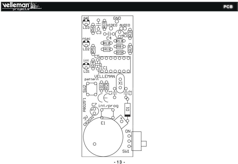
14 pF C1 27pF C2 220n C5 LD1 4MHz X1 10µF C6 1N4007 D1 220n C4 1n C3 RA5/T1CKI/T1OSI/OSC1/CLKIN 2 RA3/MCLR/Vpp/T1G/SS 4 RC5/MDCIN2/RX/DT/CCP1/P1A 5 RC4/MDOUT/TX/CK/P1B/SRNQ/C2OUT 6 RC3/AN7/MDMIN/SS/P1C/C12IN3-/CPS7 7 RA4/AN3/T1G/SDO/CLKR/T1OSO/CLKOUT/OSC2/CPS3 3 CPS0/CIN+/DACOUT/TX/CK/ICSPDAT/ICDDAT/AN0/RA0 13 CPS1/C12IN0-/VREF/SRI/RX/DT/ICSPCLK/AN1/RA1 12 CPS2/T0CKI/INT/C1OUT/SQR/FLT0/AN2/RA2 11 CPS6/C12IN2-/P1D/SDO/MDCIN1/AN6/RC2 8 CPS5/C12IN1-/SDA/SDI/AN5/RC1 9 CPS4/C2IN+/SCL/SCK/AN4/RC0 10 VDD VSS 14 PIC16LF1823-I/P or 1825 IC1 68K R1 680 R4 680 R7 68K R3 180 R10 1K R R R9 330 R8 Prog/Interlaced Patern GND LD3 680 R6 LD2 680 R5 68K R2 LITHIUM CELL 3V CR2032 E1 VID GND AUD PAL Interlaced NTSC ON SW1 120 R13 SW2 SW3 10uF C7 Diagram

15 Velleman NV Legen Heirweg Gavere (België)

16 The new Velleman Projects catalogue is now available. Download your copy here: Modifications and typographical errors reserved - Velleman nv. H8025 IP Velleman NV, Legen Heirweg Gavere.

POCKET AUDIO GENERATOR K8065
 POCKET AUDIO GENERATOR K8065 Great little gadget for service repair, testing, education, etc... ILLUSTRATED ASSEMBLY MANUAL H8065IP-1 VELLEMAN NV Legen Heirweg 33 9890 Gavere Belgium Europe www.velleman.be
MAINS VOLTAGE DETECTOR K7101
 With this device wires can be very easily checked for mains voltage. H7101IP-1 MAINS VOLTAGE DETECTOR K7101 VELLEMAN NV Legen Heirweg 33 9890 Gavere Belgium Europe www.velleman.be www.velleman-kit.com
DUAL ELECTRONIC DICE K3400
 DUAL ELECTRONIC DICE K3400 Cheating is no longer possible! ILLUSTRATED ASSEMBLY MANUAL H3400IP-1 VELLEMAN NV Legen Heirweg 33 9890 Gavere Belgium Europe www.velleman.be www.velleman-kit.com Features &
Total solder points: 147 Difficulty level: beginner 1 2 3 4 5 advanced VIDEO SIGNAL CLEANER K8036 ILLUSTRATED ASSEMBLY MANUAL
 Total solder points: 147 Difficulty level: beginner 1 2 3 4 5 advanced VIDEO SIGNAL CLEANER K8036 Digitally cleans the video signal of unwanted distortions and improves the picture quality. ILLUSTRATED
SYMMETRIC 1A POWER SUPPLY K8042
 SYMMETRIC 1A POWER SUPPLY K8042 Low cost universal symmetric power supply ILLUSTRATED ASSEMBLY MANUAL H8042IP-1 Features & Specifications Features low cost universal symmetric power supply just add a suitable
Total solder points: 115 Difficulty level: beginner 1 2 3 4 5 advanced 4 CHANNEL RUNNING LIGHT K8032 ILLUSTRATED ASSEMBLY MANUAL
 Total solder points: 115 Difficulty level: beginner 1 2 3 4 5 advanced 4 CHANNEL RUNNING LIGHT K8032 Ideal for creating disco light effects, light speed adjustable. Suited for inductive loads. ILLUSTRATED
GUITAR PREAMPLIFIER WITH HEADPHONE OUTPUT K4102
 H4102IP-1 GUITAR PREAMPLIFIER WITH HEADPHONE OUTPUT K4102 Practice the guitar without disturbing others. Features & Specifications Features: An electric guitar cannot be connected to just any amplifier
The new Velleman Projects catalogue is now available. Download your copy here: www.vellemanprojects.eu
 The new Velleman Projects catalogue is now available. Download your copy here: www.vellemanprojects.eu Modifications and typographical errors reserved - Velleman nv. H8098 IP 2 (rev.1.0) Velleman NV, Legen
Total solder points: 18 Difficulty level: beginner 1 2 3 4 5 advanced UNIVERSAL POWER SUPPLY 5-14DC / 1A K2570 ILLUSTRATED ASSEMBLY MANUAL
 Total solder points: 18 Difficulty level: beginner 1 2 3 4 5 advanced UNIVERSAL POWER SUPPLY 5-14DC / 1A K2570 The easy way to power your projects. ILLUSTRATED ASSEMBLY MANUAL H2570IP-1 Features & Specifications
K2570 UNIVERSAL POWER SUPPLY 5-14DC / 1A. The easy way to power your ILLUSTRATED ASSEMBLY MANUAL
 Total solder points: 18 Difficulty level: beginner 1 2 3 4 5 advanced UNIVERSAL POWER SUPPLY 5-14DC / 1A K2570 The easy way to power your projects. ILLUSTRATED ASSEMBLY MANUAL H2570IP-1 Features & Specifications
K4401 SOUND GENERATOR. them at the touch of a button. Specifications
 SOUND GENERATOR K4401 Sound effects, tunes, sirens... 10 of them at the touch of a button. Specifications Loudspeakers output : 8 ohm/1w Line output : 1VRms. Power supply : 8 10VDC (9v battery). Max. current
Total solder points: 248 Difficulty level: beginner 1 2 3 4 5 advanced. 15 Channel infrared receiver K8050 ILLUSTRATED ASSEMBLY MANUAL
 Total solder points: 48 Difficulty level: beginner 4 5 advanced 5 Channel infrared receiver K8050 IR-Remote control transmitters allow you to control 5 opencollector contacts ILLUSTRATED ASSEMBLY MANUAL
Total solder points: 205 Difficulty level: beginner 1 2 3 4 5 advanced UNIVERSAL BATTERY CHARGER / DISCHARGER K7300 ILLUSTRATED ASSEMBLY MANUAL
 Total solder points: 205 Difficulty level: beginner 1 2 3 4 5 advanced UNIVERSAL BATTERY CHARGER / DISCHARGER K7300 Automatic (dis)charging of both NiCd and NiMH batteries. ILLUSTRATED ASSEMBLY MANUAL
Total solder points: 167 Difficulty level: beginner 1 2 3 4 5 advanced DMX CONTROLLED RELAY K8072 ILLUSTRATED ASSEMBLY MANUAL
 Total solder points: 167 Difficulty level: beginner 1 2 3 4 5 advanced DMX CONTROLLED RELAY K8072 Control a relay by means of the wellknown DMX512 protocol. ILLUSTRATED ASSEMBLY MANUAL H8072IP-1 Features
7-SEGMENT DIGITAL CLOCK
 57mm 7-SEGMENT DIGITAL CLOCK Large 57mm clock & temperature display with extra unique feature Total solder points: 263 Difficulty level: beginner 1 2 3 4 5 advanced K8089 ILLUSTRATED ASSEMBLY MANUAL H8089IP-1
15 Channel IR transmitter. Total solder points: 53 Difficulty level: beginner 1 2 3 4 5 advanced K8049 ILLUSTRATED ASSEMBLY MANUAL
 15 Channel IR transmitter Compatible with most Velleman IR receiver kits, 4 adresses allow the use of multiple receivers in one room. Total solder points: 53 Difficulty level: beginner 1 2 3 4 5 advanced
Total solder points: 57 Difficulty level: beginner 1 2 3 4 5 advanced 3 TO 30VDC / 3A POWER SUPPLY K7203 ILLUSTRATED ASSEMBLY MANUAL H7203IP-1
 Total solder points: 57 Difficulty level: beginner 1 2 3 4 5 advanced 3 TO 30VDC / 3A POWER SUPPLY K7203 A power supply for all our kits, based on a stabilised DC voltage of 30V. ILLUSTRATED ASSEMBLY MANUAL
VOLUME AND TONE CONTROL - PREAMPLIFIER K8084
 H8084IP-1 VOLUME AND TONE CONTROL - PREAMPLIFIER K8084 When using one of our amplifiers (big or small), you always need a volume control and preferably also a tone control Features & specifications When
Total solder points: 67 Difficulty level: beginner 1 2 3. 4 5 advanced UNIVERSAL TEMPERATURE SENSOR K8067 ILLUSTRATED ASSEMBLY MANUAL
 Total solder points: 67 Difficulty level: beginner 1 2 3 4 5 advanced UNIVERSAL TEMPERATURE SENSOR K8067 Ideal for connection to computer interface boards (K8000, K8055, K8047,..) ILLUSTRATED ASSEMBLY
400W MONO/STEREO AMPLIFIER
 400W MONO/STEREO AMPLIFIER Universal, robust and compact are the words to describe this amplifier. Total solder points: 264 Difficulty level: beginner 1 2 3 4 5 advanced K4005B ILLUSTRATED ASSEMBLY MANUAL
K6002 TEMPERATURE CONTROLLER. Specifications
 Total solder points: 169 + 99 + 67 Difficulty level: beginner 1 2 3 4 5 advanced TEMPERATURE CONTROLLER K6002 Unlike a normal thermostat, this kit has two outputs, one for "high" alarm and one for "low"
Total solder points: 129 Difficulty level: beginner 1 2 3 4 5 advanced LIQUID LEVEL CONTROLLER K2639 ILLUSTRATED ASSEMBLY MANUAL H2639IP-1
 Total solder points: 129 Difficulty level: beginner 1 2 3 4 5 advanced LIQUID LEVEL CONTROLLER K2639 Forgotten to turn off the tap, leaking washing machines,... Prevention is better than cure. So use this
200W DISCRETE POWER AMPLIFIER K8060
 H8060IP-1 200W DISCRETE POWER AMPLIFIER K8060 Ideal for active speaker system or subwoofer, guitar amp, home theatre systems, instrument amp, etc. Features & Specifications Specifications: Excellent value
With the K8097 4-channel stepper motor card you can drive 4 stepper motors via USB, and monitor and assign actions if needed to 5 dry contacts
 K8097 K80977IP ILLUSTRATED LU TED ASSEMBLY SEMB MANUAL H8097IP - Channel USB stepper motor card With the K8097 -channel stepper motor card you can drive stepper motors via USB, and monitor and assign actions
PC FUNCTION GENERATOR
 PC FUNCTION GENERATOR Create standard signal waves like e.g. sine, triangle and rectangle are available; other sine waves can be easily created with integrated software. Total solder points: 954 Difficulty
Total solder points: 85 Difficulty level: beginner 1 2 3 4 5 advanced MULTIFUNCTION RELAY SWITCH K8015 ILLUSTRATED ASSEMBLY MANUAL H8015IP-2
 Total solder points: 85 Difficulty level: beginner 1 2 3 4 5 advanced MULTIFUNCTION RELAY SWITCH K8015 14 Different functions including timers, switching, flashing, interval, random switching,... ILLUSTRATED
ELECTRONIC TRANSISTOR IGNITION FOR CARS K2543
 H2543IP 1 ELECTRONIC TRANSISTOR IGNITION FOR CARS K2543 Gives your car a better starting and smoother running. Suitbale for 12V and 6V systems. Features & Specifications Even the most sceptical one has
K8068 BUS DIMMER FOR HOME MODULAR LIGHT SYSTEM ILLUSTRATED ASSEMBLY MANUAL H8068IP-1
 Total solder points: 74 Difficulty level: beginner 1 2 3 4 5 advanced BUS DIMMER FOR HOME MODULAR LIGHT SYSTEM K8068 PLUG - IN module for use with home modular lights system K8006. For electronic transformers!
DIGITAL PC SCOPE. Total solder points: 625 Difficulty level: beginner 1 2 3 4 5 advanced K8031 ILLUSTRATED ASSEMBLY MANUAL
 DIGITAL PC SCOPE Digital storage oscilloscoop, using a computer and its monitor to display waveforms. All standard oscilloscope functions are available in the Windows program supplied. Total solder points:
POWERBLOCK - POWER AMPLIFIER
 POWERBLOCK - POWER AMPLIFIER This amplifier is an ideal set-up for active speaker use. Total solder points: 383 Difficulty level: beginner 1 2 3 4 5 advanced K8081 ILLUSTRATED ASSEMBLY MANUAL H8081IP-1
DUAL ELECTRONIC DICE K3400
 Total solder points: 198 Skill level : Beginner 1 2 3 4 5 Advanced DUAL ELECTRONIC DICE K3400 Features: Two independent dice Use a single or both dice at the same time Display auto shut-off saves battery
100W SUBWOOFER KIT. Total solder points: 383 Difficulty level: beginner 1 2 3 4 5 advanced K8077 ILLUSTRATED ASSEMBLY MANUAL
 100W SUBWOOFER KIT Powerful bass from a small cabinet thanks to the dual speaker principle Total solder points: 383 Difficulty level: beginner 1 2 3 4 5 advanced K8077 ILLUSTRATED ASSEMBLY MANUAL H8077IP-1
Dc to Pulse Width Modulator
 Total solder points: 82 Difficulty level: beginner 1 2 3 4 5 advanced Dc to Pulse Width Modulator Hardware: K8004 PWM range: 0 to 100% PWM frequency: 100 to 5000Hz adjustable Minimum PWM offset: 0 to 20%
Assembly and User Guide
 1 Amp Adjustable Electronic Load 30V Max, 1 Amp, 20 Watts Powered by: 9V Battery Assembly and User Guide Pico Load is a convenient constant current load for testing batteries and power supplies. The digital
K8048 PIC PROGRAMMER AND EXPERIMENT BOARD. Specifications
 Total solder points: 274 Difficulty level: beginner 1 2 3 4 5 advanced PIC PROGRAMMER AND EXPERIMENT BOARD K8048 Suitable for programming Microchip Flash PIC TM microcontrollers. Basic programming knowledge
TRANSISTOR IGNITION K2543
 Total solder points: 38 Skill level : Beginner 1 2 3 4 5 Advanced HIGH-Q TRANSISTOR IGNITION K2543 Applications : Upgrade the existing ignition system of : Cars, motorcycles, mowers, outboards, Reduces
4 channel recorder / logger
 Total solder points: 159 Difficulty level: beginner 1 2 3 4 5 advanced 4 channel recorder / logger Hardware: USB connected and powered. Four DC coupled input channels. Input resistance 1Mohm. Maximum samples
DC CONTROLLED DIMMER Manual
 Total solder points: 61 Skill level : Beginner 1 2 3 4 5 Advanced K8003 DC CONTROLLED DIMMER Manual This small but handy circuit is ideal for replacing an existing dimmer or switch, in order to be able
3.5A SUPPRESSED DIMMER K8026
 Total solder points: 29 Difficulty level: beginner 1 2 3 4 5 3.5A SUPPRESSED DIMMER K8026 Dimmer for incandescent lightbulbs and collector motors Fuse protected AC power : 110-125 or 220-240VAC 50/60Hz
Fan timer K8041. Features: Specifications :
 Total solder points: 101 Difficulty level: beginner 1 2 3 4 5 advanced Features: Fan timer K8041 Suitable for most types of ventilators Solid state switching with noise suppression Can be connected to
AXE114S BINARY CLOCK. revolution Revolution Education Ltd. Email: info@rev-ed.co.uk Web: www.rev-ed.co.uk Version 1.1 12/09/08 AXE114.PMD.
 AXE114S BINARY CLOCK Features: The PICAXE binary clock kit tells the time by lighting up blue LEDs in a binary pattern. This is a useful tool for teaching students binary code or simply just confusing/
Stereo valve power amplifier
 Stereo valve power amplifier For most of us a high power valve amplifier is unaffordable. This kit changes that, so that now everybody can enjoy that sublime "valve sound". Total solder points: 00 Difficulty
Joule Thief 3.0 Kit. June 2012, Rev 1 1 http://www.easternvoltageresearch.com Joule Thief 3.0
 Kit Instruction Manual Eastern Voltage Research, LLC June 2012, Rev 1 1 http://www.easternvoltageresearch.com HIGH BRIGHTNESS LED THIS KIT USES A 1W CREE, HIGH BRIGHTNESS LED. DO NOT STARE AT THIS (OR
Electronics and Soldering Notes
 Electronics and Soldering Notes The Tools You ll Need While there are literally one hundred tools for soldering, testing, and fixing electronic circuits, you only need a few to make robot. These tools
DET Practical Electronics (Intermediate 1)
") DET Practical Electronics (Intermediate 1) 731 August 2000 HIGHER STILL DET Practical Electronics (Intermediate 1) Support Materials CONTENTS Section 1 Learning about Resistors Section 2 Learning about
DET Practical Electronics (Intermediate 1) 731 August 2000 HIGHER STILL DET Practical Electronics (Intermediate 1) Support Materials CONTENTS Section 1 Learning about Resistors Section 2 Learning about
Total solder points: 202 Difficulty level: beginner 1 2 3 4 5 advanced. PIC programmer board K8076 ILLUSTRATED ASSEMBLY MANUAL
 Total solder points: 0 Difficulty level: beginner advanced PIC programmer board K0 This board can program a wide range of Microchip PIC microcontrollers ILLUSTRATED ASSEMBLY MANUAL H0IP- This device complies
!Operation:!1. Connect an external power source to J1 (+ and - IN terminals). The
. The") The CB500 Electronic Circuit Breaker is an resettable circuit breaker (fuse) that disconnects power when the trip setting is exceeded. There are 4 trip settings that can easily be changed and set during
The CB500 Electronic Circuit Breaker is an resettable circuit breaker (fuse) that disconnects power when the trip setting is exceeded. There are 4 trip settings that can easily be changed and set during
Modifying the Yaesu FT-847 External 22.625 MHz Reference Input
 Modifying the Yaesu FT-847 External 22.625 MHz Reference Input David Smith VK3HZ Introduction This document describes the modification of an FT-847 to allow an external 22.625 MHz Reference oscillator
The Radio-Kits Digital SWR meter kit Construction and user manual
 The Radio-Kits Digital SWR meter kit Construction and user manual Author - Steve Drury G6ALU List of contents Section Page no. 1. Features and specifications 2 2. Introduction 2. Construction 4. General
ECEN 1400, Introduction to Analog and Digital Electronics
 ECEN 1400, Introduction to Analog and Digital Electronics Lab 4: Power supply 1 INTRODUCTION This lab will span two lab periods. In this lab, you will create the power supply that transforms the AC wall
e-4 AWT07MLED 7 Q TFT LCD MONITOR (LED Backlighted) USER MANUAL
 USER MANUAL") Thank you for purchasing our product. Please read this User s Manual before using the product. Change without Notice AWT07MLED 7 Q TFT LCD MONITOR (LED Backlighted) USER MANUAL e-4 SAFETY PRECAUTIONS Federal
Thank you for purchasing our product. Please read this User s Manual before using the product. Change without Notice AWT07MLED 7 Q TFT LCD MONITOR (LED Backlighted) USER MANUAL e-4 SAFETY PRECAUTIONS Federal
RS232/DB9 An RS232 to TTL Level Converter
 RS232/DB9 An RS232 to TTL Level Converter The RS232/DB9 is designed to convert TTL level signals into RS232 level signals. This cable allows you to connect a TTL level device, such as the serial port on
Mirror Mount Video Monitor/Recorder with Front and Rear View Night Cameras PLCMDVR5
 Mirror Mount Video Monitor/Recorder with Front and Rear View Night Cameras PLCMDVR5 www.pyleaudio.com Instruction Manual Installation and Connection: 1. Please disconnect your car battery. 2. In the contents
AutoRanging Digital MultiMeter
 Owner's Manual AutoRanging Digital MultiMeter Model No. 82139 CAUTION: Read, understand and follow Safety Rules and Operating Instructions in this manual before using this product. Safety Operation Maintenance
AUTOMATIC CALL RECORDER JAMECO PART NO. 2163735
 AUTOMATIC CALL RECORDER JAMECO PART NO. 2163735 Experience Level: Intermediate Time Required: 1-2 Hours This project automatically records phone calls. The program, along with the adapter records each
DDS VFO CONSTRUCTION MANUAL. DDS VFO Construction Manual Issue 1 Page 1
 DDS VFO CONSTRUCTION MANUAL DDS VFO Construction Manual Issue 1 Page 1 Important Please read before starting assembly STATIC PRECAUTION The DDS VFO kit contains the following components which can be damaged
Kit 106. 50 Watt Audio Amplifier
 Kit 106 50 Watt Audio Amplifier T his kit is based on an amazing IC amplifier module from ST Electronics, the TDA7294 It is intended for use as a high quality audio class AB amplifier in hi-fi applications
QUASAR ELECTRONICS KIT No. 1015 ELECTRONIC MOSQUITO REPELLER
 QUASAR ELECTRONICS KIT No. 1015 ELECTRONIC MOSQUITO REPELLER General Description This simple circuit can prove itself worth many times its value (which is very reasonable anyway) in getting rid of mosquitoes
Martin County Amateur Radio Association. Nightfire Kits 1 LED Torch Kit 270016. Contents. Description
 Nightfire Kits 1 LED Torch Kit 270016 1 Contents Nightfire Kits LED Torch Kit 270016... 1 Description... 1 Safety and Assembly of the kit... 6 Required and Useful Tools... 7 Assembly... 8 Checkout and
Cumbria Designs T-1. SSB/CW Filter kit (4.9152MHz) User Manual
 User Manual") Cumbria Designs T-1 SSB/CW Filter kit (4.9152MHz) User Manual CONTENTS 1 INTRODUCTION 2 2 CIRCUIT DESCRIPTION 2 3 ASSEMBLY 2 4 TESTING 4 The Steading Stainton PENRITH Cumbria CA11 0ES UK 1 Introduction
Cumbria Designs T-1 SSB/CW Filter kit (4.9152MHz) User Manual CONTENTS 1 INTRODUCTION 2 2 CIRCUIT DESCRIPTION 2 3 ASSEMBLY 2 4 TESTING 4 The Steading Stainton PENRITH Cumbria CA11 0ES UK 1 Introduction
Review of. 4x IOcards (PCBs) Manufactured by Opencockpits
 Manufactured by Opencockpits") Review of 4x IOcards (PCBs) Manufactured by Opencockpits Intro We all know flight simulation hardware as yokes, pedals, throttle quadrant, various complete P&P modules etc. which certainly helps in creating
Review of 4x IOcards (PCBs) Manufactured by Opencockpits Intro We all know flight simulation hardware as yokes, pedals, throttle quadrant, various complete P&P modules etc. which certainly helps in creating
WHO ANSWERED FIRST? FIND OUT WITH THIS QUIZ BUZZER KIT
 WHO ANSWERED FIRST? FIND OUT WITH THIS QUIZ BUZZER KIT BUILD INSTRUCTIONS Before you put any components in the board or pick up the soldering iron, just take a look at the Printed Circuit Board (PCB).
A Versatile Audio Amplifier
 A Versatile Audio Amplifier...built around the TBA 810 Integrated Circuit You can build a versatile audio amplifier for your workbench or for any other of your audio projects...with the TBA 810 IC (Integrated
POINTS POSITION INDICATOR PPI4
 POINTS POSITION INDICATOR PPI4 Advanced PPI with Adjustable Brightness & Simplified Wiring Monitors the brief positive operating voltage across points motors when they are switched Lights a corresponding
1218-75 Watt Audiophile Audio Amplifier
 Description Quasar kit No.1218 is part of a new line of constructions which combined form a full stereo system. The line consists of the following KITS Quasar kit No.1214 6 inputs stereo selector Quasar
Auto-ranging Digital Multimeter 52-0052-2 INSTRUCTION MANUAL
 Auto-ranging Digital Multimeter 52-0052-2 INSTRUCTION MANUAL WARNING: READ AND UNDERSTAND THIS MANUAL BEFORE USING YOUR MULTIMETER. FAILURE TO UNDERSTAND AND COMPLY WITH WARNINGS AND OPERATING INSTRUCTIONS
Assembly Notes. Disclaimer:
 Assembly Notes Before you start building your kit, please take time to read the manual in full at least once to enable you to fully understand the procedures and avoid any mistakes. The following notes
Prepared by: Paul Lee ON Semiconductor http://onsemi.com
 Introduction to Analog Video Prepared by: Paul Lee ON Semiconductor APPLICATION NOTE Introduction Eventually all video signals being broadcasted or transmitted will be digital, but until then analog video
SYSTEM 4C. C R H Electronics Design
 SYSTEM 4C C R H Electronics Design SYSTEM 4C All in one modular 4 axis CNC drive board By C R Harding Specifications Main PCB & Input PCB Available with up to 4 Axis X, Y, Z, A outputs. Independent 25
Build A Video Switcher. Reprinted with permission from Electronics Now Magazine September 1997 issue
 Build A Video Switcher Reprinted with permission from Electronics Now Magazine September 1997 issue Copyright Gernsback Publications, Inc.,1997 BUILD A VIDEO SWITCHER FRANK MONTEGARI Watch several cameras
Kit 27. 1W TDA7052 POWER AMPLIFIER
 Kit 27. 1W TDA7052 POWER AMPLIFIER This is a 1 watt mono amplifier Kit module using the TDA7052 from Philips. (Note, no suffix.) It is designed to be used as a building block in other projects where a
K8055 Specifications:
 Total solder points: 159 Difficulty level: beginner 1 2 3 4 5 advanced USB Experiment interface board K8055 Specifications: 5 Digital inputs (0= ground, 1= open). On board test buttons provided. 2 Analog
TEACHING RESOURCES SCHEMES OF WORK DEVELOPING A SPECIFICATION COMPONENT FACTSHEETS HOW TO SOLDER GUIDE GET IN TUNE WITH THIS FM RADIO KIT. Version 2.
 TEACHING RESOURCES SCHEMES OF WORK DEVELOPING A SPECIFICATION COMPONENT FACTSHEETS HOW TO SOLDER GUIDE GET IN TUNE WITH THIS FM RADIO KIT Version 2.0 Index of Sheets TEACHING RESOURCES Index of Sheets
SECURITY CAMERA INSTRUCTION MANUAL ENGLISH VERSION 1.0 LBC5451. www.lorextechnology.com
 SECURITY CAMERA INSTRUCTION MANUAL ENGLISH VERSION 1.0 LBC5451 www.lorextechnology.com Contents 1x Camera and mounting stand 1x Power adapter 1x Mounting kit 1x Allen key 1x Screw cap 1x 60 ft. (18m)
Electronics. Discrete assembly of an operational amplifier as a transistor circuit. LD Physics Leaflets P4.2.1.1
 Electronics Operational Amplifier Internal design of an operational amplifier LD Physics Leaflets Discrete assembly of an operational amplifier as a transistor circuit P4.2.1.1 Objects of the experiment
The RSGB Centenary Receiver Project Construction Manual
 The RSGB Centenary Receiver Project Construction Manual Page 1 of 12 Introduction This project is intended for those new to radio construction. It is a fairly simple receiver for the 14MHz (20m) amateur
Modular I/O System Analog and Digital Interface Modules
 OPERATING INSTRUCTIONS Modular I/O System Analog and Digital Interface Modules Installation Operation Maintenance Document Information Document ID Title: Operating Instructions Modular I/O System Part
COLOR TFT LCD MONITOR. User Manual
 COLOR TFT LCD MONITOR User Manual GENERAL INFORMATION Thank you for choosing our TFT LCD(liquid crystal display) monitor. This product employs integrate circuits, low power consumption, and no radiation
LAB 1 TECHNICAL DOC 3 IN ONE LAB DEVICE. Velleman Legen Heirweg 33 9890 Gavere Belgium
 LAB 1 TECHNICAL DOC 3 IN ONE LAB DEVICE Velleman Legen Heirweg 33 9890 Gavere Belgium SPECIFICATIONS DIGITAL MULTIMETER 3 1/2 backlit LCD Automatic polarity indication DC voltage 200mV to 600V in 5 steps
ARDUINO SEVERINO SERIAL SINGLE SIDED VERSION 3 S3v3 (REVISION 2) USER MANUAL
 USER MANUAL") ARDUINO SEVERINO SERIAL SINGLE SIDED VERSION 3 S3v3 (REVISION 2) USER MANUAL X1: DE-9 serial connector Used to connect computer (or other devices) using RS-232 standard. Needs a serial cable, with at least
ARDUINO SEVERINO SERIAL SINGLE SIDED VERSION 3 S3v3 (REVISION 2) USER MANUAL X1: DE-9 serial connector Used to connect computer (or other devices) using RS-232 standard. Needs a serial cable, with at least
The basic set up for your K2 to run PSK31 By Glenn Maclean WA7SPY
 The basic set up for your K2 to run PSK31 By Glenn Maclean WA7SPY I am by no means an expert on PSK31. This article is intended to help someone get on PSK31 with a K2. These are the things I did to get
Permanent Magnet Motor Kit, Magnetic Reed Type. (SKY-ReedMotorKit) Instructions
 Instructions") Permanent Magnet Motor Kit, Magnetic Reed Type (SKY-ReedMotorKit) Instructions This kit contains powerful permanent magnets. Exercise caution when handling them as they can pull on iron tools and snap
Permanent Magnet Motor Kit, Magnetic Reed Type (SKY-ReedMotorKit) Instructions This kit contains powerful permanent magnets. Exercise caution when handling them as they can pull on iron tools and snap
Rutland 913 Windcharger Fault Finding Guide
 Rutland 913 Windcharger Fault Finding Guide Document No. SM-133 Issue A LOW VOLTAGE CHARGE CURRENT? TE 4 REGULATOR TE 5 REG RETURN REG TO MANUFACTURER CHARGE CURRENT INTERMITTENT CHARGE CURRENT SUFFICIENT
WARNING! REQUIRED TOOLS & SUPPLIES: HIGH VOLTAGE
 INSTRUCTIONS Product: GEM Electric Motorcars Models: All Subject: Instructions for installing Stereo Accessory Estimated Completion Time:.75 Hours Parts: See Page # 7 REQUIRED TOOLS & SUPPLIES: (1) 3/8
LIGHT COMPUTER K5201
 Total solder points: 240 Skill level : Beginner 1 2 3 4 5 Advanced LIGHT COMPUTER K5201 Features: Sixteen different patterns and 7 outputs provide a unique light show Easy pattern selection with rotary
Userʼs Manual. 7 Color LCD TV & Monitor V7000
 Userʼs Manual 7 Color LCD TV & Monitor V7000 Dear Customers Thank you for purchasing the ikan V7000 7 LCD TFT Monitor. This product employs new integrate circuitry, and a high quality TFT LCD panel. It
Xenon HID Lighting System
 Automotive Safety Systems User Installation Manual Preface Specifications Thank you for purchasing NOVABLUE Xenon H.I.D. (High Intensity Discharge) vehicle lighting systems. Before installing this product,
User's Guide. True RMS Industrial Multimeter
 User's Guide 97650 True RMS Industrial Multimeter Ω C ã F ã 10A V µ 10A V ã ã ma A Introduction This meter measures AC/DC Voltage, AC/DC Current, Resistance, Capacitance, Frequency (electrical & electronic),
GLOLAB Universal Telephone Hold
 GLOLAB Universal Telephone Hold 1 UNIVERSAL HOLD CIRCUIT If you have touch tone telephone service, you can now put a call on hold from any phone in the house, even from cordless phones and phones without
DS1307 Real Time Clock Breakout Board Kit
 DS1307 Real Time Clock Breakout Board Kit Created by Tyler Cooper Last updated on 2015-10-15 11:00:14 AM EDT Guide Contents Guide Contents Overview What is an RTC? Parts List Assembly Arduino Library Wiring
BMD16N-SD. version 1.2
 BMD16NSD version 1.2 Feedback decoder with 16 contacts with integrated current detection for the S88bus Compatible with a.o. Märklin Digital, Uhlenbrock Intellibox, Fleischmann TwinCenter and LDT HSI88
HDMI/DVI to VGA/Component & Audio Break out Converter
 HDMI/DVI to VGA/Component & Audio Break out Converter User Manual (HCV VA) All information is subject to change without notice. All names & trademarks are property of their respective owners. Rev.1002
SPECIFICATIONS. Recommended Battery sizes (Maintenance) AUTOMOTIVE 150 650CCA 150 750CCA MARINE 200 700MCA 200 850MCA DEEP CYCLE 17 55Ah 17 80Ah
 AUTOMOTIVE 150 650CCA 150 750CCA MARINE 200 700MCA 200 850MCA DEEP CYCLE 17 55Ah 17 80Ah") WARNING Read the operating instructions before use. Lead Acid Batteries can be dangerous. Ensure no sparks or flames are present when working near batteries. Eye protection should be used. Make sure the
WARNING Read the operating instructions before use. Lead Acid Batteries can be dangerous. Ensure no sparks or flames are present when working near batteries. Eye protection should be used. Make sure the
Nixie Clock Universal Kit V1.08. Assembly and Operation. Software Version 6.3 Revision 11. 11. 2012
 Nixie Clock Universal Kit V1.08 Assembly and Operation Software Version 6.3 Revision 11. 11. 2012 This document is copyrighted. No parts of this documentation may be used commercially. Nixie Clock Kit
step 1 Unpack the lunchbox And check whether you have got all the components~ If you have questions please contact us at: info@unitunlikely.
 step 1 Unpack the lunchbox And check whether you have got all the components~ If you have questions please contact us at: info@unitunlikely.com This part is called the PCB (printed circuit board). All
HP4000EX Hardware Manual
 INFORMATION TO USER CAUTION RISK OF ELECTRIC SHOCK, DO NOT OPEN! CAUTION: TO REDUCE THE RISK OF ELECTRIC SHOCK, DO NOT REMOVE COVER (OR BACK). NO USER SERVICEABLE PARTS INSIDE. REFER SERVICING TO QUALIFIED
GSM HOME SECURITY SYSTEM
 Cell /Mobile phone home security system GSM HOME SECURITY SYSTEM Model : GSM-120 TABLE OF CONTENTS 1. FEATURES... 1 2. APPLICATION... 2 3. SPECIFICATIONS... 3 4. FRONT PANEL & LAYOUT DESCRIPTION...6 5.
Controlling a Dot Matrix LED Display with a Microcontroller
 Controlling a Dot Matrix LED Display with a Microcontroller By Matt Stabile and programming will be explained in general terms as well to allow for adaptation to any comparable microcontroller or LED matrix.
The $25 Son of a cheap timer This is not suitable for a beginner. You must have soldering skills in order to build this kit.
 The $25 Son of a cheap timer This is not suitable for a beginner. You must have soldering skills in order to build this kit. Micro Wizard has been manufacturing Pinewood Derby timers for over 10 years.
Build a Voltage and Current Peak Detector
 ax You Can DIY! Build a Voltage and Current Peak Detector Here is a simple portable device that can help answer the question about peak voltage and peak current requirements and whether or not your power