|
|
|
- Francine Underwood
- 8 years ago
- Views:
Transcription
1 TECHNICAL SERVICE DEPARTMENT Removal, Cleaning, & Reinstallation of the Burner Assembly For models 74 & GT199 Required tools - #2 Phillips screwdriver (At least 8 long and magnetic) - Needle nose pliers - Air compressor (If this is not available then a can of air like you would use to clean a computer keyboard). Warning! During this procedure you may encounter some sharp edges. Please be careful. Wearing gloves may protect against injury. NOTE: Read these entire instructions before starting this procedure. A. Initial Disassembly 1) Turn off Remote 2) Disconnect electrical power 3) Turn off gas supply 4) Turn off water supply 5) Remove front door (4 screws). 6) Remove screw(s) holding PCB ( 1 to 3 screws depending on model). Allow PCB to hang by wires. Fig.1

2 B. Burner Plate Cover 1) On the burner plate cover, remove the two retaining clips and screws from the manifold supply tubes. (Screws 19 thru 23) See Figure 1. 2) At the gas valve, remove the three retaining clips and screws from each of the gas manifold tubes. Note the brass colored tube has a special clip; the silver colored tubes have a different clip. See Figure 2. Note: Each manifold tube has a rubber o-ring on each end to seal the tube. Ensure these are not lost or damaged. If o-rings are not on the end of the tube then verify they are in manifold fuel rail and gas valve (No need to move them just do not lose them). 3) Remove the two screws that hold the igniter mounting plate. (Screws 17 & 18) Allow to hang. 4) Remove the two screws that hold the door switch. (Screws 10 & 11) Allow to hang. 5) Remove the remaining 14 screws on the burner cover plate. Do not forget to re-connect the green and yellow striped ground wire when reassembling cover plate. (Screw 8) 6) Pull off burner cover. Note: The burner cover has a gasket. The gasket will tear a little and this is OK. Do not scrap off or apply any type of sealant. During reassembly just straighten gasket and reinstall the cover. Fig.2 C. Burner Assembly 1) Pull black rubber grommets outward. (The grommets can also be white) See Figure 3. Note positioning of the four black grommets. 2) Remove the three screws on the bottom back wall of the burner assembly. See Figure 4. Fig. 3
.")
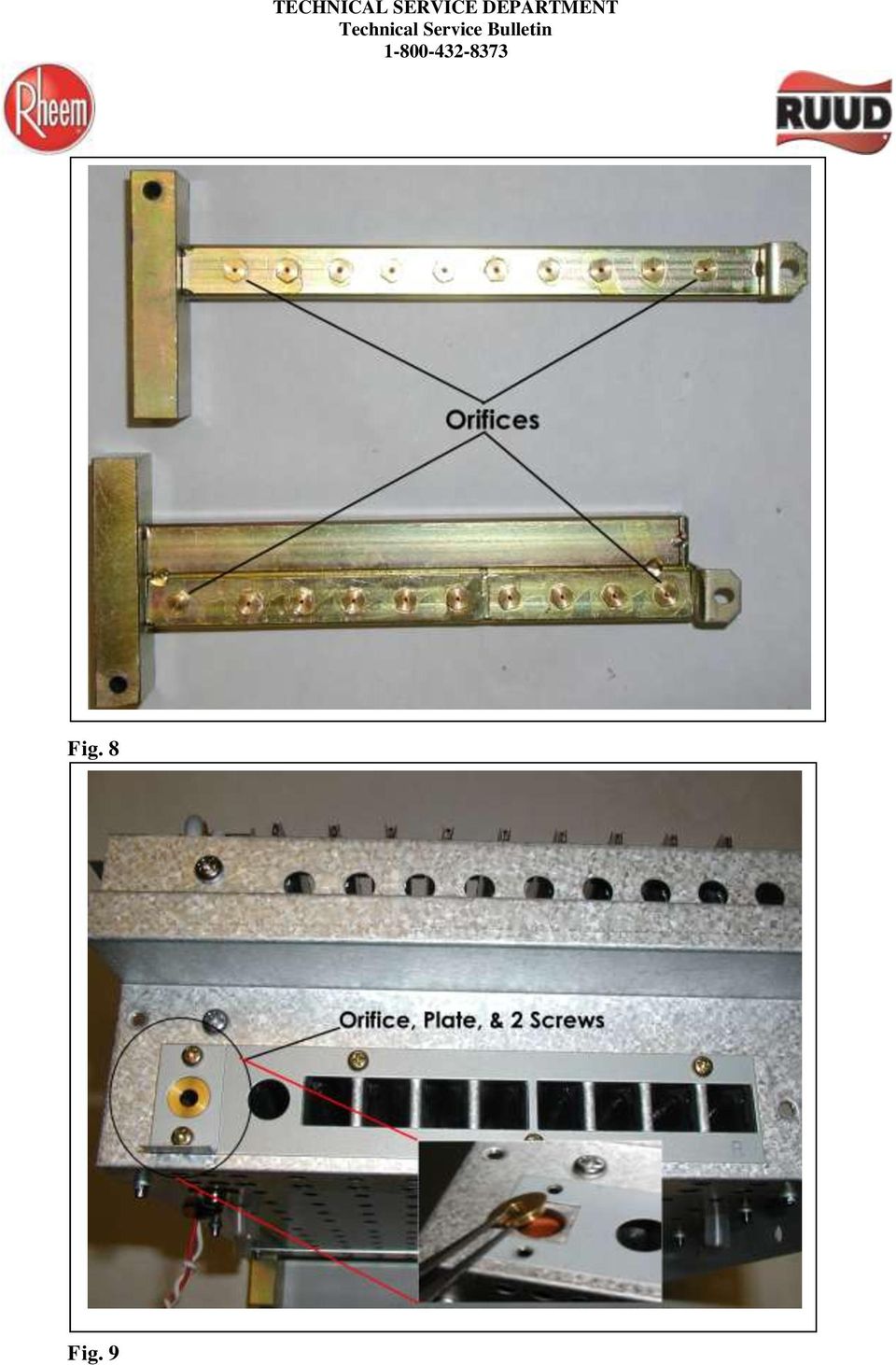
3 3) Slowly but firmly pull straight out on both sides of the burner assembly to slide it out of the chassis. Note: Be careful as the Flame Rods can get caught by the top of the burner opening. This could damage or bend the flame rods. See Figure 5. 4) Disconnect all igniter wires and flame probe wires (This can be done at the PCB or burner assembly). Note the position of each wire. 5) Disconnect ODS Molex on PCB at connector Q (Red & White twisted wires). 6) Remove manifold fuel rails on both sides of the burner. Two screws on each rail. 7) Inspect the burner rail, closely inspect all orifices for any debris or clogging. Clean with compressed air by blowing back through the nozzle. A small needle or fine wire can be used to help clear the openings. Do not enlarge the openings. 8) On the right side of burner toward the front, remove the small rectangle plate and brass orifice. Note position in which these items are installed. See figure 9. 9) Inspect the igniters and flame rods for damage. Using steel wool, emery cloth, or fine sandpaper (no less than 100 grit), clean the ends of the igniter/flame rods (5 in all). Take care not to damage the ceramic base. 10) Using compressed air blow back down through all burner ribbons. Fig. 4 Fig. 5
 Inspect the burner rail, closely inspect all orifices for any debris or clogging. Clean with compressed air by blowing back through the nozzle.")
4 Fig. 6 Fig. 7

5 Fig. 8 Fig. 9
6 D. ODS Removal 1) On the bottom you will find a screw with a washer, remove this screw and washer. See Figure 10. 2) Locate the ODS wire harness, Red and White wire that is twisted together. From the bottom of the burner assembly push the orange grommet with the red and white wires into the burner and out of the hole. Carefully pull the wires up through the hole and pass the white Molex connector through the hole. See Figure 10. 3) Locate the burner shield plate, remove the screw holding the plate from the top of the burner, next remove the screw holding the plate from the side of the ODS assembly, remove the plate. See Figure 11. 4) Locate the ODS mounting screw, remove the screw securing the ODS to the burner, the wire harness may have to be moved slightly out of the way. Do not excessively bend the grey wires connecting to the ODS sensor, damage could occur. See Figure 11. 5) With a slight twisting motion, slide the ODS out from the mounting location away from the side of the burner assembly. Fig. 10
 Locate the burner shield plate, remove the screw holding the plate from the top of the burner, next remove the screw holding the plate from the side of the ODS assembly, remove the plate.")
7 Fig. 11 E. ODS Examination & Disassembly 1) Examine the opening to the ODS for any debris that might be clogging the intake port. 2) Locate the ODS case screw, and carefully remove this screw. Note: it is a stainless steel screw and can be easily dropped. It is also very tight. Place ODS Assembly down on a hard surface to remove the screw. See Figure 12. 3) Slowly twist the upper section of the ODS while holding the brass base, slide the section off the base, this must be done straight up. Note: the ceramic element is loose inside the ODS and could fall out or be damaged if the section is not removed straight. 4) Remove the ceramic element and inspect the holes for any blockage or buildup, clean with compressed air. Fig. 13 See Figure 13. 5) Remove the brass ring and set aside. Do Not Remove any other components such as the thermocouple and wires. 6) Inspect the base for any debris, and use compressed air to clean.

8 Fig. 12 F. ODS Reassembly 1) Set the Brass ring back into the brass base. 2) Set the ceramic element into the brass ring, this has to be set straight in, otherwise damage could occur. 3) Now, slowly slip the upper section down over the ceramic element and brass base, this has to be done straight on, otherwise damage could occur. DO NOT FORCE. 4) Using a twisting motion seat the upper section fully down on the brass base and align the screw hole. You may need to hold both pieces to get it to align properly. 5) Install the small stainless steel screw; be careful as to not cross thread the screw. Note: Do not operate without this screw in place, do not substitute another screw. 6) Slip the ODS assembly into the side of the burner, align the rear mounting hole and secure with the short silver screw. See Figure 14. 7) Press the bottom of the ODS assembly towards the fuel rail to ensure the seal is made with the side of the burner assembly, install the silver screw with the lock washer, and large brass washer on the bottom of the burner assembly to secure the ODS and make sure the ODS assembly is sitting straight and vertical. See Figure 15. 8) Reattach the burner shield plate with the two silver screws. 9) Ensure all screws are tight.
 Install the small stainless steel screw; be careful as to not cross thread the screw. Note: Do not operate without this screw in place, do not substitute another screw.")
9 10) Thread the ODS wires (red & white twisted wire pair) back through the hole in the bottom of the burner assembly and press the seal into the bottom. Fig. 14 Fig. 15 G. Installation of Burner Assembly & PCB 1) Reattach the igniter and flame rod wires to each rod base as previously disconnected. Ensure rubber tubing covers the connection. (If you disconnected the flame rod wires from PCB then wires are still connected appropriately and proceed to next step.) Note: Water heaters manufactured before October 2006 (0906 date code and earlier) will have flame rod 1 and the right igniter wire reversed. See Figure 16.

10 Fig. 16 2) Slide burner assembly back into place. Note: Be careful not to damage the igniter and flame rods. 3) Ensure wires are in the appropriate grommets and slide grommets into bottom of burner assembly housing. Note: Ensure grommets are in proper position. 4) Install the 3 screws into bottom of burner assembly and tighten. 5) Position burner plate cover and start installing screws (Do not tighten the screws until all is installed). Screws 1 thru 9 and 12 thru 16 (Figure 1). Note: Ensure ground is attached (screw 8). 6) Position door switch and install screws 10 and 11 (Figure 1). 7) Position igniter coil and install screws 17 & 18 (Figure 1). 8) Reinstall burner manifold tubes. Ensure clips are in the correct location. Screws 19 to 23 (See figures 1 & 2). Note: Each manifold tube has a rubber o-ring on each end to seal the tube. Ensure these are installed. 9) Ensure all screws are tightened on the cover plate and the burner manifold tubes (Be careful not to strip the screws).
. Note: Ensure ground is attached (screw 8). 6) Position door switch and install screws 10 and 11 (Figure 1).")
11 10) Reinstall PCB. 11) Reconnect ODS Molex on PCB at connector Q (Red & White twisted wires). 12) Ensure all other connectors are attached. See Figure 17 for completely assembled unit. 13) Replace front cover and install the 4 screws. 14) Reconnect power. 15) Turn on water supply. 16) Turn on Gas Supply 17) Turn on remote. 18) Turn on hot water faucet and ensure proper operation of heater. Fig. 17
 Turn on Gas Supply 17) Turn on remote.")
Cleaning Instructions, Pilot Replacement and Valve Change. Model No.: 233010 Natural Gas
 Cleaning Instructions, Pilot Replacement and Valve Change Model No.: 233010 Natural Gas 8mm open-end wrench 9mm open-end wrench 10mm open-end wrench 12mm open-end wrench 13mm open-end wrench Phillips screw
HP Laser Jet 4200/4240/4250/4300/4350 Swing Plate
 HP Laser Jet 4200/4240/4250/4300/4350 Swing Plate 1 Swing Plate Assembly-RM1-0043 1 Swing Plate Kit-5851-2766 (RM1-0043 plus RM1-1091 gear) CAUTION: Fuser may be hot. Turn off printer, unplug it and allow
Installation Instructions 4508 4508S
 SYMPHONY Spread Lavatory Faucet with Speed Connect Drain Congratulations on purchasing your American Standard faucet with Speed Connect drain, a feature found only on American Standard faucets. Speed Connect
Cleaning Instructions for Burner, Pilot Assembly, and Emitter Screen Series: 220000-450000
 Cleaning Instructions for Burner, Pilot Assembly, and Emitter Screen Series: 220000-450000 10 mm open end wrench 12 mm open end wrench 9/16 open end wrench 5/8 open end wrench 11/16 open end wrench 9/16
INSTALL/REMOVAL INSTRUCTIONS: WINDOW REGULATOR
 REMOVAL/INSTALL OF WINDOW REGULATOR (741-306) Honda Accord 2003 07 General Tech Tips: Use painter s tape rather than duct tape to secure window. It will not damage paint or leave sticky residue. A plastic
3. SEISCO PARTS & SERVICE REMOVAL AND REPAIR GUIDE
 4 3. SEISCO PARTS & SERVICE REMOVAL AND REPAIR GUIDE A. Changing the Control Board B. Replacing a Heating Element C. Thermistor Replacement D. High Limit Switch Replacement E. Level Detector Replacement
M A N U A L 13-10-05
 Documentation The following information sheets illustrate the description below: 12-WW01-4G-E Sectional view of the lance with main dimensions 12-W101-6G-E Sectional view of the head of the lance with
INSTALLATION INSTRUCTIONS
 INSTALLATION INSTRUCTIONS Application Outboards Faria 5 Gauge Set* Publication No. Description Part Number Honda Code PII53606A White faced, flat lens 06300-ZW5-010ZB 6315410 Issue Date Black faced, flat
Installation Instructions 6028.801
 DAZZLE Installation Instructions 08.80 Spread Lavatory Faucet with Speed Connect Drain* Congratulations on purchasing your American Standard faucet with Speed Connect drain, a feature found only on American
Solstice/Sky Water Pump Replacement
 Solstice/Sky Water Pump Replacement The water pump on the Solstice/Sky is starting to need replacement on some vehicles. This guide will help in replacing the water pump while the engine is still in the
PARTS NEEDED FOR CONVERTING FROM LP TO NG
 1 6 7 8 3 5 4 10 9 2 PARTS NEEDED FOR CONVERTING FROM LP TO NG Number Description 1 30" NG Manifold 2 NG side burner valve 3 NG Regulator 4 Rear I/R NG orifice 4 Rear I/R NG orifice 5 Side burner NG orifice
Cleaning Instructions for Burner, Pilot Assembly, and Emitter Screen. Series: 150000 200605 LP Gas
 Cleaning Instructions for Burner, Pilot Assembly, and Emitter Screen Series: 150000 200605 LP Gas Tools needed Bottle brush Non-abrasive scouring pad Small utility brush Heavy-duty pipe cleaners Air hose
Triac Printed Circuit Board Replacement
 Technical Service Bulletin: Triac Printed Circuit Board Replacement TRONIC 5000C Pro Models: WH17, WH27, WH36 Introduction Fig. 1 ELECTRICITY IS EXTREMELY DANGEROUS. TAKE EXTRA PRECAUTIONS AND ENSURE ALL
GENUINE PARTS INSTALLATION INSTRUCTIONS
 GENUINE PARTS INSTALLATION INSTRUCTIONS 1. DESCRIPTION: Auto-Dimming Mirror Kit with Compass and HomeLink 2. APPLICATION: Titan 3. PART NUMBER: 999L1 WS000 4. KIT CONTENTS: Item Qty Description Service
TOYOTA Tundra 2007 - BACK-UP CAMERA SYSTEM Preparation
 Preparation Part Number(s): PT233-34070, PT923-35070-11, PT923-35070-43 NOTE: Part number of this accessory may not be the same as part number shown. Back Up Monitor Kit Contents PT923-35070-11 / PT923-35070-43
5800 Temperature Sensor Cable Assembly
 5800 Temperature Sensor Cable Assembly Removal and Replacement Instruction Sheet #60-4702-070 Revision D, January 14, 2013 Overview The 5800 has two refrigeration temperature sensors, one attached to the
Figure 2 The fan and shroud also needs to be removed for access to the four a/c compressor bolts and removal of the compressor from the top.
 Here are some pictures to show what s required when replacing the A/C compressor, expansion valve and receiver/drier on a 2001 Volvo V70. Even if you don t replace these A/C parts these pictures can help
430 Power/Electronics Replacement
 Replacing the main board WARNING Before proceeding, turn off the main power switch and unplug the power cord. Caution Make sure you are properly grounded with an ESD strap before continuing. The main printed
M-9424-463V Intake Manifold INSTALLATION INSTRUCTIONS
 Please visit www.fordracingparts.com for the most current instruction information!!! PLEASE READ ALL OF THE FOLLOWING INSTRUCTIONS CAREFULLY PRIOR TO INSTALLATION. AT ANY TIME YOU DO NOT UNDERSTAND THE
Navico-Northstar 2kW JRC Radar Package, Scanner Cable Removal and Replacement
 Navico-Northstar 2kW JRC Radar Package, Scanner Cable Removal and Replacement This work instruction describes the methods and means for which to remove and reinstall optional scanner cable configurations
FRONT BUMPER INSTALLATION INSTRUCTIONS 2007-2011 DODGE / MERCEDES SPRINTER
 Aluminess Products Inc 9402 Wheatlands Ct. #A Santee, CA 92071 619-449-9930 FRONT BUMPER INSTALLATION INSTRUCTIONS 2007-2011 DODGE / MERCEDES SPRINTER Please read before beginning Stainless steel hardware
Before repairing your toilet, you must determine
 Before repairing your toilet, you must determine which type of toilet you have. Pressurized Toilets If you have a pressurized toilet, it is recommended that you call a licensed plumbing contractor to repair
Document number RS-PRD-00130 Revision 05 Date 20/10/2009 Page 1/30
 Date 20/10/2009 Page 1/30 1. Purpose This document describes the field replacement of the footscan plate cable for these models: 2m hi-end plate SN 11/5/xxx 2m pro plate SN 7/5/xxx 0.5m 2003 hi-end plate
PRODUCT: WASHER / WASHER-DRYER COMBO MODEL: AW 120 / AW 122 / AW 125 AWD 120 / AWD 121 / AWD 129
 PRODUCT: WASHER / WASHER-DRYER COMBO MODEL: The information included in this Splendide Repair Manual may change without notice. Please see our web site www.splendide.com/service/docs.html for updates,
Mazda CX7 2007-09 99-7508
 INSTALLATION INSTRUCTIONS FOR PART 99-7508 APPLICATIONS Mazda CX7 2007-09 99-7508 KIT FEATURES DIN Radio Provision with Pocket ISO Mount Radio Provision with Pocket Double DIN Mount Radio Provision Stacked
INSTALLATION & OPERATING INSTRUCTIONS
 INSTALLATION & OPERATING INSTRUCTIONS WARNING RISK OF ELECTRIC SHOCK. CONNECT ONLY TO A CIRCUIT PROTECTED BY A GROUND-FAULT CIRCUIT-INTERRUPTER. THE UNIT SHOULD BE INSTALLED BY A QUALIFIED SERVICE REPRESENTATIVE.
Installation Instructions 4662.003
 Installation Instructions.00 SINGLE CONTROL KITCHEN FAUCET Thank you for selecting American-Standard...the benchmark of fine quality for over 00 years. To ensure that your installation proceeds smoothly--please
SERVICE MANUAL. Flammable Vapor Ignition Resistant Water Heaters. Gas Water Heaters. Troubleshooting Guide and Instructions for Service
 http://waterheatertimer.org/how-to-troubleshoot-gas-water-heater.html Flammable Vapor Ignition Resistant Water Heaters Gas Water Heaters SERVICE MANUAL Troubleshooting Guide and Instructions for Service
RULE # 1 is DON T mess with things that you don t know anything about! (Take them to a pro & pay them to fix it)
") OK there seems to be a LOT of problems noted on KatRiders having to do with CARBS, so I thought I d write out sort of a checklist of things to help folks. RULE # 1 is DON T mess with things that you don
OK there seems to be a LOT of problems noted on KatRiders having to do with CARBS, so I thought I d write out sort of a checklist of things to help folks. RULE # 1 is DON T mess with things that you don
P7100 PUMP INSTALLATION INSTRUCTIONS Diesel Care & Performance Inc
 P7100 PUMP INSTALLATION INSTRUCTIONS Diesel Care & Performance Inc Installation Timing Pin Location CAUTION: Before installing the injection pump, be sure that number 1 cylinder is at the Top Dead Center
Juice Box Stages 1&2 135&335 Installation Guide 5/10/08
 Tools Required: 8mm socket or nut driver Small flat head screwdriver Electrical tape, masking tape, or shrink tube Pep talk: Although the install looks daunting at first, once you get the learning curve
INGROUND, ROPED, AND HOLELESS JACK SEAL REPLACEMENT
 D. L. Martin Company INGROUND, ROPED, AND HOLELESS JACK SEAL REPLACEMENT TYPICAL HYDRAULIC JACK HEAD ASSEMBLY 1 TOOLS REQUIRED: 1) Container to hold hydraulic fluid. 2) Clean rags and protective covers
CONTENTS TOOLS REQUIRED: Ratchet 13mm Socket 10mm Socket Phillips Screwdriver Pliers Panel Removal Tool. Amp Installation
 CONTENTS 1EA. SUBWOOFER ASSEMBLY P/N RUWRANGLER 1EA. 200 WATT AMP/BRACKET ASSEMBLY P/N RM11JKBTL - Bracket P/N RE08BTL200R - Amp 1EA. POWER HARNESS P/N RHWRANGLERPWR 1EA. OVERLAY HARNESS P/N RHWRANGLER
Overview PARTS LIST. B. Lever mounting base C. Flush handle assembly D. Grey/Blue float stop E. Grey float (Full Flush) F. Flush valve washer
 F. Flush valve washer") Overview READ ENTIRE INSTRUCTIONS BEFORE STARTING INSTALLATION PARTS LIST A. Flush valve B. Lever mounting base C. Flush handle assembly D. Grey/Blue float stop E. Grey float (Full Flush) F. Flush valve
Overview READ ENTIRE INSTRUCTIONS BEFORE STARTING INSTALLATION PARTS LIST A. Flush valve B. Lever mounting base C. Flush handle assembly D. Grey/Blue float stop E. Grey float (Full Flush) F. Flush valve
Depending on which elastic support you have you can secure the V2 power unit to the following seat bracket tubes: EXTERNAL DIAMETER 27.
 ASSEMBLY 1 - EPS V2 POWER UNIT (SOLUTION 5) 1.1 - POSITIONING INSIDE THE SEAT TUBE WITH ELASTIC SUPPORT IN THE SEAT BRACKET TUBE Depending on which elastic support you have you can secure the V2 power
Fading Red Tones on Color LaserJet 2600s
 Procedures Fading Red Tones on Color LaserJet 2600s HP Color LaserJets 2600n, 1600, and 2605 share the same basic Canon engine design. One aspect of the design brings the common problem of scanner optic
GENUINE PARTS INSTALLATION INSTRUCTIONS
 GENUINE PARTS INSTALLATION INSTRUCTIONS DESCRIPTION: Illuminated Kick Plate APPLICATION: Rogue (2011) PART NUMBER: 999G6 GX010 KIT CONTENTS: Item A B C G H QTY 1 1 1 D 1 E 1 F 3 15 6 Description Kick Plate,
KEYLESS ENTRY UPGRADE SECURITY SYSTEM for 2004 TOYOTA HIGHLANDER
 KEYLESS ENTRY UPGRADE SECURITY SYSTEM for 2004 TOYOTA HIGHLANDER DEALER SERVICE AND INSTALLATION MANUAL KIT NO. 00016-30915 Contents PARTS LIST... 2 PARTS ILLUSTRATIONS... 2 VEHICLE PREPARATION... 3 INSTALLING
Not required for most applications Not required for most applications High pressure (12-803 provided) High pressure (12-803 provided)
 High pressure (12-803 provided)") ELECTRIC FUEL PUMPS P/N 12-801-1, 712-801-1, 12-802-1, 712-802-1, 12-815-1, & 712-815-1 FUEL PRESSURE REGULATORS P/N 12-803, 12-501, 12-804, 12-500, & 15812NOS Installation Instructions THESE INSTRUCTIONS
ELECTRIC FUEL PUMPS P/N 12-801-1, 712-801-1, 12-802-1, 712-802-1, 12-815-1, & 712-815-1 FUEL PRESSURE REGULATORS P/N 12-803, 12-501, 12-804, 12-500, & 15812NOS Installation Instructions THESE INSTRUCTIONS
REMOVAL AND INSTALLATION
 303-01C-1 REMOVAL AND INSTALLATION Engine Body On Special Tool(s) Adapter For 303-D043 303-D043-02 or equivalent Special Tool(s) 303-01C-1 Turbocharger Lifting Bracket 303-1266 Wrench, Fan Clutch Nut 303-214
Auto Sentry-eXP Maintenance
 Auto Sentry-eXP Maintenance Maintenance Procedures for Auto Sentry exp Bill Dispenser Credit Card Reader Bill Acceptor Bill Dispenser Maintenance Bill Dispenser Problem / Cause Bill Dispenser Error Codes
Jake's Big Airbox Modification
 1 sur 12 29/11/2012 16:32 Jake's Big Airbox Modification Captain Jake, the Mel Bay of Motorcycle Modification presents: FREE YOUR AIRBOX! What follows is documentation and photographs of the airbox modification
WARNING! REQUIRED TOOLS & SUPPLIES: HIGH VOLTAGE
 INSTRUCTIONS Product: GEM Electric Motorcars Models: All Subject: Instructions for installing Stereo Accessory Estimated Completion Time:.75 Hours Parts: See Page # 7 REQUIRED TOOLS & SUPPLIES: (1) 3/8
The Bradford White. Save this manual for future reference. (To be performed ONLY by qualified service providers)
") The Bradford White R (To be performed ONLY by qualified service providers) R U130T*FRN U130S*FRN U140T*FRN U1403T*FRN U1403S*FRN U1404T*FRN U1503*FRN U150L*FRN U1504S*FRN U430T*FRN U440T*FRN U4403S*FRN
The Bradford White R (To be performed ONLY by qualified service providers) R U130T*FRN U130S*FRN U140T*FRN U1403T*FRN U1403S*FRN U1404T*FRN U1503*FRN U150L*FRN U1504S*FRN U430T*FRN U440T*FRN U4403S*FRN
Acer Aspire One AOA150-1570 Disassembly
 Acer Aspire One AOA150-1570 Disassembly Model The Acer Aspire One AOA150-1570 is the model with the 120GB hard drive (not the Flash drive) and 1GB RAM with Windows XP. Disassembly Beware of the ESD (ElectroStatic
Installation Instructions
 Installation Instructions For Use with PXPV230, PXPV265, PXPD230, and PXPD265 models Attention! - Please read these instructions completely before attempting installation. Always unplug the power supply
Your safety and the safety of others are very important.
 NATURAL GAS TO PROPANE CONVERSION KIT 090 INSTALLATION INSTRUCTIONS FOR ALTITUDES 0 -,00 FT. ONLY PROPANE CONVERSION KIT SAFETY... INSTALLATION REQUIREMENTS... Tools and Parts... LP Gas Requirements...
Installation instructions, accessories - Handsfree for cellular phone, system B, entry level
 XC90 Section Group Weight(Kg/Pounds) Year Month 3 39 0.5/1.1 2006 07 XC90 2003, XC90 2004 IMG-249663 Page 1 of 18 Required tools A0000162 A0000163 IMG-239664 M0000232 IMG-253123 IMG-252223 Page 2 of 18
ENGINE FUEL FUEL FILTER... FUEL HEATER... INJECTOR... SUPPLY PUMP... COMMON RAIL... FUEL PRESSURE LIMITTER...
 FUEL FILTER............................ FUEL HEATER.......................... INJECTOR.............................. SUPPLY PUMP.......................... COMMON RAIL.......................... FUEL PRESSURE
ASK THE EXPERT: Burner Troubleshooting Information & Maintenance
 ASK THE EXPERT: Burner Troubleshooting Information & Maintenance The burner is the heart of your BBQ. It is subject to a number of conditions that can cause damage, and lead to potential safety issues.
Table of Contents. www.hunterfan.com. What to Expect with. Preparation. Tools Needed. Wiring. Hanging the Fan. Blades. Motor Housing.
 www.hunterfan.com Table of Contents What to Expect with Your Installation 30 inches Hanging the Fan Wiring 8 Maintenance, Operation & Cleaning Light Kit 13??? 14 1 9 Troubleshooting 11 5 Blades Motor Housing
www.servicechamp.com
 1-800-221-0216 Fax: 1-800-472-2281 www.servicechamp.com Service Champ Part 52081 Service Interval every 30,000 miles / Chevrolet 1992-2002 6.5 liter Description and Operation The fuel filter element separates
Replacing N-300 PCB. 2014 YZ Systems for use by YZ s distribution network and end-users. www.yzsystems.com
 Replacing N-300 PCB Replacing N-300 PCB Record all Parameters and other operational information from The N-300 if Possible for Use in Programing The new PCB. If Parameters are not Obtainable from The Old
Fleck 4650. Service Manual INSTALLATION AND START-UP PROCEDURE TABLE OF CONTENTS JOB SPECIFICATION SHEET
 Fleck 4650 Service Manual TABLE OF CONTENTS JOB SPECIFICATION SHEET...1 INSTALLATION AND START-UP PROCEDURE...1 CONTROL VALVE DRIVE ASSEMBLY...2 CONTROL DRIVE ASSEMBLY FOR CLOCK...3 BYPASS VALVE ASSEMBLY...4
INSTALLATION INSTRUCTIONS FOR 2006-2009 VW MK5
 CI100018 INSTALLATION INSTRUCTIONS FOR 2006-2009 VW MK5 Rabbit, Jetta 2.5L These instructions are applicable to vehicles equipped with either manual or automatic transmissions Thank you for choosing to
2008 ACCORD - Front Knuckle/Hub/Wheel Bearing Replacement (page 18-13)
") 2008 ACCORD - Front Knuckle/Hub/Wheel Bearing Replacement (page 18-13) Exploded View Special Tools Required Ball joint remover, 28 mm 07MAC-SL0A202 Hub dis/assembly tool 07GAF-SD40100 Bearing driver attachment,
2008 ACCORD - Front Knuckle/Hub/Wheel Bearing Replacement (page 18-13) Exploded View Special Tools Required Ball joint remover, 28 mm 07MAC-SL0A202 Hub dis/assembly tool 07GAF-SD40100 Bearing driver attachment,
R O A D M A S T E R, I N C.
 R O A D M A S T E R, I N C. 11 10 20 12 4 18 19 1 2 13 16 ITEM QTY NAME MATERIAL 1...2... 1/2" x 3 1/2" BOLT... 350103-00 2...2... 1/2" x 2" BOLT... 350097-00 3...6... 1/2" x 1 1/2" BOLT... 350095-00 4...2...
800-551-1943. HP Laser Jet 2400 Series Fixing Drive Side Plate Assembly Fixing Drive Side Plate Assembly- RM1-1500 page 1
 Fixing Drive Side Plate Assembly- RM1-1500 page 1 CAUTION: Fuser may be hot. Turn off printer, unplug it and allow it to sit for 20 to 30 minutes before performing these maintenance procedures. Fixing
Owner s Guide and Installation Manual. Vancouver Model Name. 21321, 21328 Model No. English Español
 For Your Records and Warranty Assistance For reference, also attach your receipt or a copy of your receipt to the manual. Vancouver Model Name 21321, 21328 Model No. Type A Models Owner s Guide and Installation
Cleaning & Sanitisation
 Cleaning & Sanitisation Notice: The information and/or procedures presented in the following demonstration(s) should be performed by a trained Water Cooler Service Technician only. Never attempt to service
Gas Oven Repair Guide
 - /6 - Gas Oven Repair Guide [ FX70*, FX50*] Ver. Aug-0 Ignition Failure Cooktop ignition Oven ignition Heating defect Oven Cooktop Abnormal Flame Button, Motors Lamp Others Smell, Smoke, Noise No Display,
COOLING SYSTEM Section Page
 5 COOLING SYSTEM Section Page 5.1 COOLANT PRE-HEATER... 5-3 5.2 COOLANT PUMP NON-EGR ENGINE... 5-7 5.3 COOLANT PUMP EGR ENGINE... 5-13 5.4 FRONT CONNECTOR HOUSING NON-EGR ENGINE... 5-17 5.5 FRONT CONNECTOR
Trillium 40 Axis Spring Tensioner Wire Replacement Instructions
 Trillium 40 Axis Spring Tensioner Wire Replacement Instructions 1 Overview The objective is to replace the broken axis spring tensioner wire. This requires the following tasks: 1. Remove the seismometer
Munchkin Heat Exchanger Maintenance
 Munchkin Heat Exchanger Maintenance By: Mike Granahan *Refer to the appropriate boiler manual for your specific model number. Adjustment procedures will vary. Boiler shown below is an HTP Munchkin 80M
The Drink-Aide The NEW look of independence
 The Drink-Aide The NEW look of independence Introducing Drink-Aide What is Drink-Aide? The Drink-Aide is a water bottle that attaches easily to a wheelchair for use by persons with little or no upper
Build Your Own Solar Car Teach build learn renewable Energy! Page 1 of 1
 Solar Car Teach build learn renewable Energy! Page 1 of 1 Background Not only is the sun a source of heat and light, it s a source of electricity too! Solar cells, also called photovoltaic cells, are used
Cooling system components, removing and installing
 Page 1 of 34 19-1 Cooling system components, removing and installing WARNING! The cooling system is pressurized when the engine is warm. When opening the expansion tank, wear gloves and other appropriate
Owners & Installation Manual for the Sheridan, Mountainair, Pine Valley and Old Forge Ceiling Fan Family
 Owners & Installation Manual for the Sheridan, Mountainair, Pine Valley and Old Forge Ceiling Fan Family Part of the Kiva Lighting Family Custom Lighting and Fans Since 1992 1312 12th St NW Albuquerque,
TOYOTA TUNDRA 2015 Billet Grille w/led DRL
 TOYOTA TUNDRA 2015 Billet Grille w/led DRL Part Number: 00016-34088 Accessory Code: BG3000 Conflicts Models 1794 and Platinum Kit Contents Item # Quantity Reqd. Description 1 2 LED DRL 2 1 Driver Box 3
MGB Chrome Bumper Conversion
 MGB Chrome Bumper Conversion Installation Instructions For 1974 1/2-1980 MGB This kit requires cutting, welding, and painting. Professional installation recommended. Note: Every MGB body is slightly different
Replacement parts. WM97+ gas-fired water boiler Boiler Manual. OBTAIN PARTS ONLY THROUGH WEIL-McLAIN THE BOILER CONTAINS CERAMIC FIBER MATERIALS
 Replacement parts DO NOT SERVICE THE BOILER WITHOUT A WM97+ MAINTENANCE KIT AVAILABLE Failure to adhere to these guidelines can result in severe personal injury, death or substantial property damage. The
INSTALLATION MANUAL INSIDE PASSENGER COMPARTMENT. HFC 134a FOR EUROPEAN SPEC. / GENERAL SPEC. AIR CONDITIONING ENGLISH
 HFC 134a Ozone Friendly Refrigerant FOR EUROPEAN SPEC. / GENERAL SPEC. AIR CONDITIONING ENGLISH AAAMU-60 / INSIDE PASSENGER COMPARTMENT INSTALLATION MANUAL 2000 (EUROPE) B.V.. All Rights Reserved. This
Installation and Troubleshooting Instructions for Electric Tankless Residential Water Heaters.
 Model Number: Serial Number: Information Manual Installation and Troubleshooting Instructions for Electric Tankless Residential Water Heaters. ATTENTION: IF YOU ARE NOT A LICENSED PLUMBER OR A LICENSED
Rebuild Instructions for 70001 and 70010 Transmission
 Rebuild Instructions for 70001 and 70010 Transmission Brinn, Incorporated 1615 Tech Drive Bay City, MI 48706 Telephone 989.686.8920 Fax 989.686.6520 www.brinninc.com Notice Read all instructions before
Beautifully Traditional
 Arcade 800mm Single Sliding Door Quadrant - nickel Arcade 900mm Single Sliding Door Quadrant - nickel ARC48 ARC49 INSTALLATION INSTRUCTIONS A www.arcadebathrooms.com IMPORTANT - Please read before installation
VOYAGER 570G. 744A Sprayer Control
 VOYAGER 570G 744A Sprayer Control U S E R M A N U A L U S E R M A N U A L Table of Contents CHAPTER 1 - INTRODUCTION...1 SYSTEM CONFIGURATIONS...1 KIT CONTENTS...3 CONTROL HOUSING ASSEMBLY...5 CHAPTER
ADDING AN ELECTRIC AUXILIARY FAN TO RADIATOR STACK ON 03 ALPINE COACH
 ADDING AN ELECTRIC AUXILIARY FAN TO RADIATOR STACK ON 03 ALPINE COACH The original design of the 03 Alpine Coaches (and perhaps other years as well) did not include any kind of engine fan engage mechanism
Fuel Injection Pump, Rotary (005-014)
") Fuel Injection Pump, Rotary View Related Topic Page 1 of 30 Fuel Injection Pump, Rotary (005-014) Table of Contents Summary General Information Preparatory Steps Remove Front Gear Train Rear Gear Train
Fuel Injection Pump, Rotary View Related Topic Page 1 of 30 Fuel Injection Pump, Rotary (005-014) Table of Contents Summary General Information Preparatory Steps Remove Front Gear Train Rear Gear Train
Powers Controls TH 192 HC Heating/Cooling Room Thermostat
 Powers Controls TH 192 HC Heating/Cooling Room Thermostat Technical Instructions Document No. 155-066P25 TH 192-2 50 60 70 80 70 TH0356R1 60 80 POWERS Description The TH 192 HC thermostats are proportional
with installation dynafact boost GAUGE this manual is for use with systems 64050-64054
 owners manual with installation instructions dynafact boost GAUGE this manual is for use with systems 64050-64054 GENERAL INSTALLATION PRACTICES This manual is an installation guide for all 1. Banks DynaFact
http://waterheatertimer.org/how-to-troubleshoot-gas-water-heater.html
 http://waterheatertimer.org/how-to-troubleshoot-gas-water-heater.html TECHNICAL SERVICE DEPARTMENT Effective October 2007, we transitioned to the White Rodgers (Intelli-Vent TM )Thermostat Control for
Drive shaft, servicing
 Volkswagen Passat B6 - Drive shaft, servicing Стр. 1 из 41 40-7 Drive shaft, servicing Drive shafts, overview I - Assembly overview: Drive axle with CV joint VL100 40-7, Drive axle with CV joint VL100,
UNIT 7: PLUMBING KEY CONCEPTS. 1. Identify tools for plumbing. 2. Location of shutoff valves for the main and individual fixtures
 KEY CONCEPTS 1. Identify tools for plumbing 2. Location of shutoff valves for the main and individual fixtures 3. How water is supplied to your home 4. How waste water is removed and treated 5. Common
Gripper Kit for the Boe-Bot Robot (#28202)
") 599 Menlo Drive, Suite 100 Rocklin, California 95765, USA Office: (916) 624-8333 Fax: (916) 624-8003 General: info@parallax.com Technical: support@parallax.com Web Site: www.parallax.com Educational: www.stampsinclass.com
599 Menlo Drive, Suite 100 Rocklin, California 95765, USA Office: (916) 624-8333 Fax: (916) 624-8003 General: info@parallax.com Technical: support@parallax.com Web Site: www.parallax.com Educational: www.stampsinclass.com
USE &CARE GUIDE. Remote Faucet Pump System. See Important Safeguards on page 2
 Remote Faucet Pump System USE &CARE GUIDE See Important Safeguards on page 2 An exclamation point within an equilateral triangle is intended to alert user to the presence of important operating and maintenance
INSTALL/REMOVAL INSTRUCTIONS: WINDOW LIFT MOTOR
 REMOVAL/INSTALL OF WINDOW LIFT MOTOR (742-273) Ford Expedition 1997 2002, Lincoln Navigator 1998 2002, Ford F-150 Super Crew Cab 2001 General Tech Tips: Use painter s tape rather than duct tape to secure
How To: Retrofit the Morimoto Mini D2S bi-xenon Projectors
 How To: Retrofit the Morimoto Mini D2S bi-xenon Projectors Warning: By reading this document I agree that it is only intended to be used as an educational guide. The Retrofit Source Inc. makes no guarantee
Char-Lynn Hydraulic Motor. Repair Information. 10 000 Series. October, 1997
 Char-Lynn Hydraulic Motor October, 1997 Repair Information Geroler Motor Two Speed 001 27 Retainer inside bore of valve plate bearingless motors only 4 15 16 3 6 35 Parts Drawing 25 2 2 1 19 17 36 40 47
AXLE SHAFTS - FRONT. 1998 Pontiac Bonneville MODEL IDENTIFICATION DESCRIPTION & OPERATION TROUBLE SHOOTING REMOVAL & INSTALLATION
 AXLE SHAFTS - FRONT 1998 Pontiac Bonneville 1998-99 DRIVE AXLES FWD Axle Shafts - Cars - "C", "G" & "H" Bodies GM Aurora, Bonneville, Eighty Eight, LeSabre, LSS, Park Avenue, Regency, Riviera MODEL IDENTIFICATION
Step 1. Item 6. Item 1
 Voltage Regulators QD3/T350 Motor Replacement Kit Kit Number 57A63675100B Service Information S225-50-35 Contents General..................................... 1 Parts Supplied...............................
BILLET HEADLAMP WITH SHORT/TALL MOUNTS
 -J099 REV. 00-0- BILLET HEADLAMP WITH SHORT/TALL MOUNTS GENERAL Kit Number 9-0, 9-0 Models Kit 9-0 is a -/ inch headlamp and kit 9-0 is a -/ inch headlamp. Both kits will fit the models listed in Table.
BUILT-IN DISHWASHER INSTALLATION INSTRUCTIONS
 BUILT-IN DISHWASHER INSTALLATION INSTRUCTIONS PLEASE READ COMPLETE INSTRUCTIONS BEFORE YOU BEGIN LEAVE INSTALLATION INSTRUCTIONS AND USER'S GUIDE WITH OWNER ALL ELECTRIC WIRING AND PLUMBING MUST BE DONE
Z-Truck (Vertical Moving) Z-truck Flag. Y-Truck (Horizontal Moving) FIGURE 1: VIEW OF THE Z-TRUCK. Flexshaft Assembly
 Z-truck Flag. Y-Truck (Horizontal Moving) FIGURE 1: VIEW OF THE Z-TRUCK. Flexshaft Assembly") Replacing the Cover Micro-Switch To remove and replace the Cover Micro-Switch you will need the following tools: #2 Phillips screwdriver (magnetic tip preferred) #1 Phillips screwdriver (magnetic tip preferred)
Replacing the Cover Micro-Switch To remove and replace the Cover Micro-Switch you will need the following tools: #2 Phillips screwdriver (magnetic tip preferred) #1 Phillips screwdriver (magnetic tip preferred)
A&A CORVETTE PERFORMANCE C6 BOOST & FUEL GAUGE INSTALLATION INSTRUCTIONS
 A&A CORVETTE PERFORMANCE C6 BOOST & FUEL GAUGE INSTALLATION INSTRUCTIONS 1. Check your gauges before you take them out of the packaging to make sure they are at 0 (zero) psi for both boost and fuel pressure.
Manual for GlobePharma Mini-Press II Rotary Tablet Press
 1 of 13 Preparing the Rotary Press 1. Make sure the rotary press is unplugged. 2. Open the bottom cabinet of the rotary press and take out the grey tool kit, and the beige box of punches and dies. 3. Take
Make sure oven is OFF. Never remove parts or touch the fan unless the oven is OFF.
 Morning Cleaning The following start-up procedures MUST be completed before using the oven. The procedures may be completed at night after the oven has completed the clean cycle, or in the morning BEFORE
AM/FM ANTENNA KIT (TOUR-PAK MOUNT)
") -J077 REV. 008-0-0 AM/FM ANTENNA KIT (TOUR-PAK MOUNT) GENERAL Kit Number 7-98A Models For model fitment information, see the P&A Retail Catalog or the Parts and Accessories section of www.harley-davidson.com
-J077 REV. 008-0-0 AM/FM ANTENNA KIT (TOUR-PAK MOUNT) GENERAL Kit Number 7-98A Models For model fitment information, see the P&A Retail Catalog or the Parts and Accessories section of www.harley-davidson.com
Front axle components, overview
 just a test. Front axle components, overview 40-1 General Information Load bearing components and parts of the suspension must not be welded or straightened. Vehicles without drive axle must not be moved,
INSTALLATION MANUAL. Installation Instructions
 INSTALLATION MANUAL Power-Pole Signature Series Shallow Water Anchor Installation Instructions CAUTION: Read this instruction manual carefully. Become familiar with the controls and know how to operate