K128. USB PICmicro Programmer. DIY Electronics (HK) Ltd PO Box 88458, Sham Shui Po, Hong Kong. mailto:
|
|
|
- Osborne Bradford
- 7 years ago
- Views:
Transcription
1 K128 USB PICmicro Programmer DIY Electronics (HK) Ltd PO Box 88458, Sham Shui Po, Hong Kong mailto: Last Modified March

2 Board Construction The board is quite easy to construct but it is advisable to read through these notes before starting. The USB chip and all other surface mount components have been premounted to make construction easier. WARNING Be aware that the USB chip is sensitive to static electricity discharge and could be damaged by mishandling of the PCB. Be careful with the board and avoid touching any of the tracks or pads while assembling it. Try to handle it only by the edges. The other chip in this kit is also sensitive to static discharge. This is the PIC16F628. Do not touch the pins and only handle it by the ends. A socket is supplied to allow for upgrades and easy assembly.

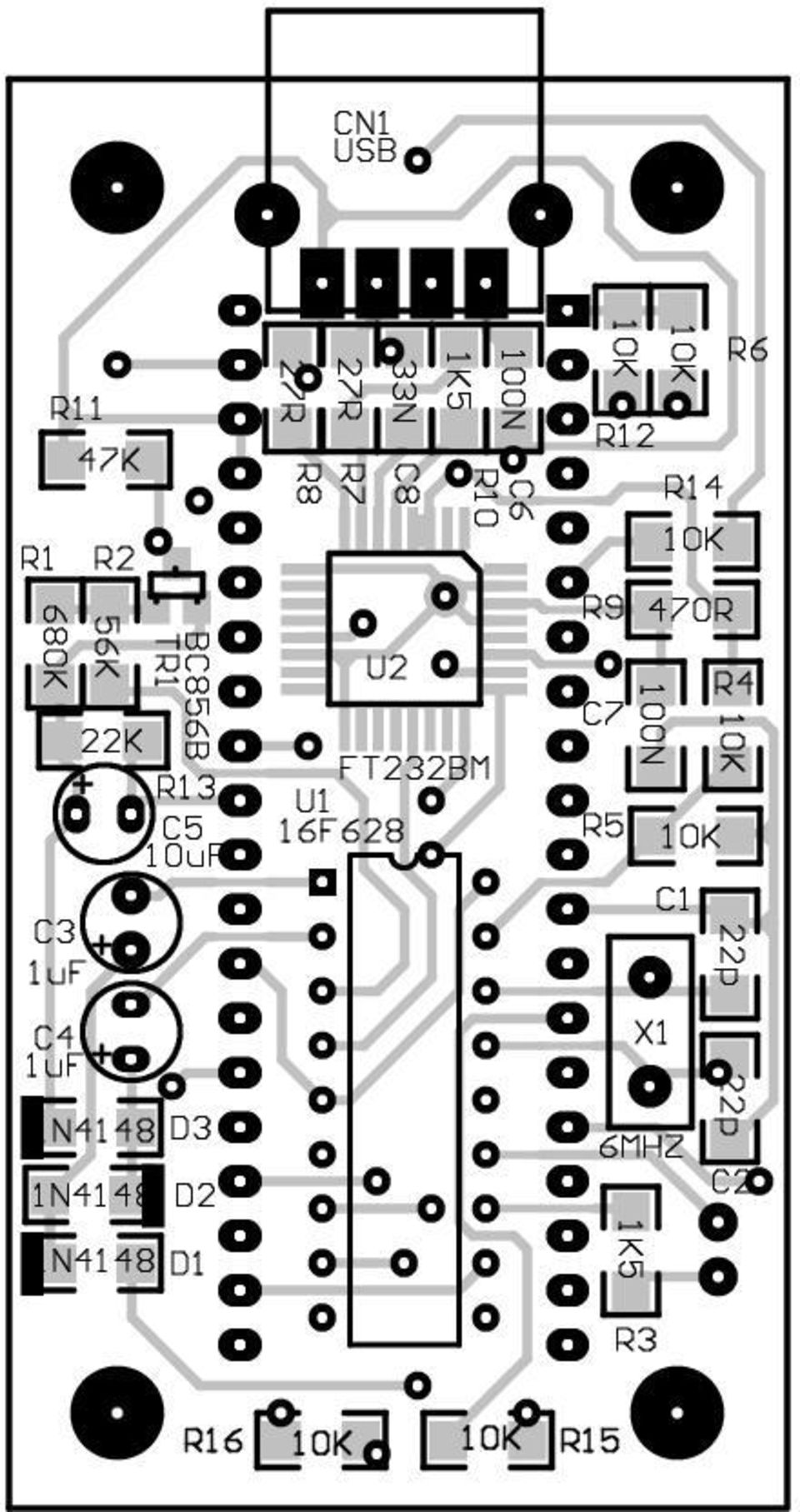
3 Starting The first thing to do is inspect the PCB for shorted or open tracks or other damage, especially to the premounted components. Be aware of the static warning when doing this check. When you are satisfied that all is well, then you can proceed. ALL COMPONENTS EXCEPT FOR THE LED AND ZIF SOCKET MOUNT ON THE BOTTOM SIDE OF THE PCB. Start by mounting the 6MHz crystal. Before soldering it, make sure there is a small gap (~ 1mm) between it and the PCB. This is to keep the metal can of the component from shorting its own mounting pads. Next, mount the 18 pin IC socket for the PIC16F628 chip. The indented end faces towards the USB chip. When placing the socket, make sure the pins are flush with the top of the PCB surface and not protruding above it before soldering. Before soldering the USB connector, trim the 4 connector pins and the two support pins so that these leads are flush with the PCB top surface when inserted into the PCB. The pins for the above two components have to be made flush with the PCB top surface otherwise the extra pin lengths won t allow the ZIF socket to sit flat on the PCB surface. Next, mount all the electrolytic capacitors. These are polarity sensitive components so make sure they are mounted properly. The positive lead is longer than the negative lead, and the negative lead is also marked on the side of the capacitor. On the PCB overlay, there are holes marked [+] as the positive lead for each of these components. There are 2 x 1uF and 1 x 10uF capacitors so please try not to get them mixed up. See the PCB overlay for the correct mounting positions.

4 There is one LED that can be mounted next. Make sure it are oriented correctly and is mounted from the TOP PCB side. The anode (A) is marked on the PCB and is the longer of the two leads on the component. The Cathode has a flat surface on the LED body and is also marked on the board as (K). Very carefully check your work at this stage, as the next part to mount is the ZIF socket. After mounting, this component hides a lot of soldered connections and will make error corrections very difficult. Inspect the board for dry or unsoldered joints and check all components for correct orientation and placement. Now insert the preprogrammed PIC16F628 into its socket. Pin 1 is towards the USB socket. The finished board should look like the images shown here. This completes the construction phase.

5 USB Drivers To enable USB capability for your PC and this project you will need to install a special driver. This is a piece of software that handles the communications between the PC and the special USB chip on the programmer PCB. Create a USB driver sub directory into the directory where your programmer software was installed. C:\diyprog was the default. Therefore you would have a new directory called C:\diyprog\usb. The drivers come in 2 flavours, plug and play support and no plug and play support. As this programmer does not have plug and play support, that narrows it down to 1 choice. You will need to visit this web page and download this driver. VCP drivers for Win 98/2000/ME/XP (without PNP support) Download and unzip the file into the newly created USB directory. Now visit this other web page and download the PDF application note that describes how to install the driver for your particular system. For example you would download... AN for Win 98 AN for Win2000 Download the PDF file into the USB driver directory listed above. Open and follow the simple directions given in the PDF file. This should only take a few minutes to do. When the driver installation is completed, connect a USB cable from the PC to the programmer board. This will power the board. At this stage you may get a message from Windows saying that it has found new hardware.

6 Also the LED should flash on and change colors briefly. If not, monitor and check the PCB components and make sure nothing gets too hot. If the PIC gets too hot to touch, disconnect the USB cable immediately as the PIC is most likely inserted the wrong way around. If this is the case, then they are quite tough little chips and it may have survived. Insert it the correct way and re-connect the USB cable. If the LED flashed as described earlier then it should be ok. Disconnect the cable and insert the PCB into the mounting box provided with the kit. The PCB will be a nice snug fit and no screws should be necessary to hold it in place. Now run MicroPro.exe which is the Windows driver interface supplied with the kit. Click [File] -> Port or double click the COM x label on screen to bring up the COM port window. Select the COM port that you selected for use for USB communications while installing the driver, then OK. If you don t know what port it is connected to, click on START - > Settings -> Control Panel. Then double click System. Look for the Device Manager and go to Ports (COM & LPT). You will see COM x listed next to the USB label. X will be the COM port number for you to select in the MicroPro program. The PC may take a short while to establish communications with the USB port. When it has done so, the COM port number will appear on screen and the programmer is ready for use on the USB port. From MicroPro, make sure that Kit 128 is selected by clicking on FILE -> Programmer Style -> K128. If all is well, as a simple system test, click on OPTIONS -> Reset Programmer You should see the LED change color, then stay red. You should also see Board Connected appear on the MicroPro message bar.

7 Now select 16F84 from the chip select menu and click on Read. You should see the LED change to green while the programmer reads from a non existant chip. The screen will most likely fill with 0000's or 3FFF s. Your new programmer is now ready for use. When using the USB interface, always connect the programmer to the PCB before starting MicroPro.exe, and close MicroPro before disconnecting the programmer. Failure to use this power up - power down sequence may result in a stalled PC for a minute or so because of the non responding USB port.

8 PARTS LIST Used Part Type Designators Description SEMICONDUCTORS 1 FT232BM U2 USB Converter 1 PIC16F628 U1 Preprogrammed Microcontroller 3 1N4148 D1, D2, D3 Diode 1 BC856B TR1 PNP Transistor 1 6MHz X1 Crystal 1 LED L1 Bi-Color RESISTORS all R R7, R R R9 2 1K5 R3, R10 7 R4, R5, R6, R12, R14, R15, R K R K R K R K R1 CAPACITORS 2 22p C1, C Ceramic 1 33N C Ceramic 2 100N C6, C Ceramic 2 1uF C3, C4 16V Electrolytic 1 10uF C5 50V Electrolytic MISCELLANEOUS 1 Presoldered PCB PCB pin ZIF socket SKT1 1 18pin IC SOCKET 1 UT-5676 CN2 USB Connector 1 Plastic Box

9 A B C D D C B A Title Number Revision Size C Date: 31-Mar-2003 Sheet of File: C:\DIYPRO~1\PROGRA~1\SCHEMS\K128.SCH Drawn By: C1 22p C2 22p X1 6MHZ RA0 17 RA1 18 RA2 1 RA3 2 RA4 3 RB0 6 RB1 7 RB2 8 RB3 9 RB4 10 RB5 11 RB6 12 RB7 13 MCLR 4 OSC1 16 OSC2 15 Gnd 5 14 U1 16F628 D1 1N4148 D2 1N4148 D3 1N4148 C3 1uF C4 1uF C5 10uF UTX R1 680K R2 56K VPP CLOCK DATA L1 PGM R3 1K5 LEDA URX XTAL R4 R5 C6 100N R7 27R R8 27R R9 470R R10 1K5 C8 33N C7 100N XTAL UTX URX USBP USBM CN1 USB USBP USBM A USBDP 7 USBDM 8 3V3OUT 6 XTIN 27 XTOUT 28 TEST 31 RESET# 4 EECS 32 EESK 1 EEDATA 2 RSTOUT# 5 A SLEEP# 10 RXLED# 11 TXLED# 12 PWRCTL 14 PWREN# 15 TXDEN 16 RI# 18 DCD# 19 DSR# 20 DTR# 21 CTS# 22 RTS# 23 RXD 24 TXD 25 U2 FT232BM MCLR R6 MCLR R11 47K LEDK LEDK Vprg Vprg R13 22K LEDA TR1 BC856B R SKT1 PROGRAMMER R15 R14 DATA DATA DATA CLOCK CLOCK CLOCK VPP CLOCK DATA R16

10

11
12

13

TEECES DOME LIGHTING SYSTEMS
 This lighting system was designed by John V (Teeces) to be a simple, customizable, expandable and affordable solution for dome lighting. An Arduino micro-controller is used to tell LED driver chips which
AXE114S BINARY CLOCK. revolution Revolution Education Ltd. Email: info@rev-ed.co.uk Web: www.rev-ed.co.uk Version 1.1 12/09/08 AXE114.PMD.
 AXE114S BINARY CLOCK Features: The PICAXE binary clock kit tells the time by lighting up blue LEDs in a binary pattern. This is a useful tool for teaching students binary code or simply just confusing/
Joule Thief 3.0 Kit. June 2012, Rev 1 1 http://www.easternvoltageresearch.com Joule Thief 3.0
 Kit Instruction Manual Eastern Voltage Research, LLC June 2012, Rev 1 1 http://www.easternvoltageresearch.com HIGH BRIGHTNESS LED THIS KIT USES A 1W CREE, HIGH BRIGHTNESS LED. DO NOT STARE AT THIS (OR
USB / Data-Acquisition Module NOW LEAD-FREE
 USB / Data-Acquisition Module NOW LEAD-FREE DLP-TEMP-G Features: Digital I/Os, Analog Inputs (0- Volts) or any combination USB. and.0 Compatible Interface th Generation Silicon from FTDI Supports Up To
The $25 Son of a cheap timer This is not suitable for a beginner. You must have soldering skills in order to build this kit.
 The $25 Son of a cheap timer This is not suitable for a beginner. You must have soldering skills in order to build this kit. Micro Wizard has been manufacturing Pinewood Derby timers for over 10 years.
PolyBot Board. User's Guide V1.11 9/20/08
 PolyBot Board User's Guide V1.11 9/20/08 PolyBot Board v1.1 16 pin LCD connector 4-pin SPI port (can be used as digital I/O) 10 Analog inputs +5V GND GND JP_PWR 3-pin logic power jumper (short top 2 pins
!Operation:!1. Connect an external power source to J1 (+ and - IN terminals). The
. The") The CB500 Electronic Circuit Breaker is an resettable circuit breaker (fuse) that disconnects power when the trip setting is exceeded. There are 4 trip settings that can easily be changed and set during
The CB500 Electronic Circuit Breaker is an resettable circuit breaker (fuse) that disconnects power when the trip setting is exceeded. There are 4 trip settings that can easily be changed and set during
GLOLAB Universal Telephone Hold
 GLOLAB Universal Telephone Hold 1 UNIVERSAL HOLD CIRCUIT If you have touch tone telephone service, you can now put a call on hold from any phone in the house, even from cordless phones and phones without
Warnings: This manual is intended to guide a technicians or customers who would like to repair DBL's
 DBL's Service Manual Warnings: This manual is intended to guide a technicians or customers who would like to repair DBL's devices (GoIP, SIM Bank, FXS/FXO gateways) at his/her own risk. DBL SHALL NOT be
RS232/DB9 An RS232 to TTL Level Converter
 RS232/DB9 An RS232 to TTL Level Converter The RS232/DB9 is designed to convert TTL level signals into RS232 level signals. This cable allows you to connect a TTL level device, such as the serial port on
Assembly and User Guide
 1 Amp Adjustable Electronic Load 30V Max, 1 Amp, 20 Watts Powered by: 9V Battery Assembly and User Guide Pico Load is a convenient constant current load for testing batteries and power supplies. The digital
PCMCIA 1 Port RS232 2.1 EDITION OCTOBER 1999
 232 232232 PCMCIA 1 Port RS232 2.1 EDITION OCTOBER 1999 Guarantee. FULL 36 MONTHS GUARANTEE. We guarantee your interface card for a full 36 months from purchase, parts and labour, provided it has been
XBee USB Adapter Board (#32400)
") Web Site: www.parallax.com Forums: forums.parallax.com Sales: sales@parallax.com Technical: support@parallax.com Office: (916) 624-8333 Fax: (916) 624-8003 Sales: (888) 512-1024 Tech Support: (888) 997-8267
Web Site: www.parallax.com Forums: forums.parallax.com Sales: sales@parallax.com Technical: support@parallax.com Office: (916) 624-8333 Fax: (916) 624-8003 Sales: (888) 512-1024 Tech Support: (888) 997-8267
Martin County Amateur Radio Association. Nightfire Kits 1 LED Torch Kit 270016. Contents. Description
 Nightfire Kits 1 LED Torch Kit 270016 1 Contents Nightfire Kits LED Torch Kit 270016... 1 Description... 1 Safety and Assembly of the kit... 6 Required and Useful Tools... 7 Assembly... 8 Checkout and
Electronics and Soldering Notes
 Electronics and Soldering Notes The Tools You ll Need While there are literally one hundred tools for soldering, testing, and fixing electronic circuits, you only need a few to make robot. These tools
Contents. Installing the upgrade memory kit in the G450 and G430 Media Gateway May 2014 1
 Contents Installing the upgrade memory kit in the G450 / G430 Media Gateway... 3 Equipment ordering... 3 Inserting or replacing a RAM card... 4 Inserting or replacing a RAM card in the G450... 4 Replacing
ISP Engineering Kit Model 300
 TM ISP Engineering Kit Model 300 December 2013 Model 300 Overview The Model 300 programmer supports JTAG programming of all Lattice devices that feature non-volatile configuration elements. The Model 300
How to setup a serial Bluetooth adapter Master Guide
 How to setup a serial Bluetooth adapter Master Guide Nordfield.com Our serial Bluetooth adapters part UCBT232B and UCBT232EXA can be setup and paired using a Bluetooth management software called BlueSoleil
AUTOMATIC CALL RECORDER JAMECO PART NO. 2163735
 AUTOMATIC CALL RECORDER JAMECO PART NO. 2163735 Experience Level: Intermediate Time Required: 1-2 Hours This project automatically records phone calls. The program, along with the adapter records each
16-Port RS232 to USB2.0 High Speed Multi Serial Adapter (w/ Metal Case) Installation Guide
 Installation Guide") 16-Port RS232 to USB2.0 High Speed Multi Serial Adapter (w/ Metal Case) Installation Guide 1. Introduction Thank you for purchasing this 16-Port RS232 to USB2.0 High Speed Multi Serial Adapter. It is an
16-Port RS232 to USB2.0 High Speed Multi Serial Adapter (w/ Metal Case) Installation Guide 1. Introduction Thank you for purchasing this 16-Port RS232 to USB2.0 High Speed Multi Serial Adapter. It is an
How To Use An Ams 5812 Pressure Sensor With A Usb Starter Kit
 User Guide USB Starter Kit AMS 5812 Phone:+49 (0)6131/91 0730-0 Fax: +49 (0)6131/91 073-30 Internet: E Mail: info@analogmicro.de Analog Microelectronics GmbH An der Fahrt 13, D 55124 Mainz May 2012 - Rev.
NOW LEAD-FREE! VCCIO VCCIO RXLED TXLED DTR# 10K FTDI FT232R
 DLP--G USB / SERIAL ADAPTER NOW LEAD-FREE! DLP- USB Type 'B' Mini connector to Host PC/ Linux/Mac V VCC USBDP USBDM LED LED DTR# IO Voltage Select Jumper 0K User uc, up, DSP, FPGA Reset External VCC.0
Kurzweil KORE 64. ROM Expansion Board for the PC3 and PC3K
 Kurzweil KORE 64 ROM Expansion Board for the PC3 and PC3K Installation Instructions August 1, 2012 2012 Young Chang Co., Ltd. All rights reserved. Kurzweil is a product line of Young Chang Co., Ltd. Kurzweil,
Schematic & Parts List: PIC16F688 Satellite Tracker & Rotor Controller
 Fox Delta Amateur Radio Projects & Kits FD- ST1 Schematic & Parts List: PIC16F688 Satellite Tracker & Rotor Controller Introduction to Satellite Antenna Tracking: The ST1 kit/project was designed as an
WHO ANSWERED FIRST? FIND OUT WITH THIS QUIZ BUZZER KIT
 WHO ANSWERED FIRST? FIND OUT WITH THIS QUIZ BUZZER KIT BUILD INSTRUCTIONS Before you put any components in the board or pick up the soldering iron, just take a look at the Printed Circuit Board (PCB).
BUILDING INSTRUCTIONS
 etap2hw 38 mm I2C to LCD Interface BUILDING INSTRUCTIONS October 2013 P. Verbruggen Rev 1.01 15-Oct-13 Page 1 Table of Contents Chapter 1 General Information 1.1 ESD Precautions 1.2 Further Supplies 1.3
PCB Design with Altium: Schematic Entry, Libraries, and Designing Components
 PCB Design with Altium: Schematic Entry, Libraries, and Designing Components Alex Fosdick Capstone Senior Design Instructor: Tom Brown Edited: Jan 30th 2011 Description: This document is the first of two
SPY-BATT Battery Tutor Device Installation Manual Rev. 1.1-07/04/2016
 SPY-BATT Battery Tutor Device Installation Manual Rev. 1.1-07/04/2016 1. GENERAL DESCRIPTION The SPY-BATT is a device that allows to monitor the state of your battery. The SPY-BATT stores over time the
COPYRIGHT TOP NOTCH TABLETS LLC. 2012. HOW TO: Install the Drivers to your PC so you can Flash Firmware to your RK3066 Powered Tablet.
 HOW TO: Install the Drivers to your PC so you can Flash Firmware to your RK3066 Powered Tablet. 1. Inside the RKBatchTool1.5en folder you will see a sub folder called Driver 2. Inside of that folder are
Schematic & Parts List: PIC16F688 Satellite Tracker & Rotor Controller
 Fox Delta Amateur Radio Projects & Kits FD- ST1 Schematic & Parts List: PIC16F688 Satellite Tracker & Rotor Controller Introduction to Satellite Antenna Tracking: In view to encourage radio amateurs and
Manual Serial PCI Cards
 Manual Serial PCI Cards W&T Models 13011, 13410 13411, 13610 13611, 13812 Version 1.4 Subject to error and alteration 37 01/2005 by Wiesemann & Theis GmbH Subject to errors and changes: Since we can make
Programming the On-Chip Flash on a phycore-xc161 phycore-xc167
 Application Note Programming the On-Chip Flash on a phycore-xc161 phycore-xc167 Application Note Edition July 2003 LAN-020e_1 Application Note Preface...1 1 Installing Infineon MemTool...2 2 Preparing
1-10 The USB PIC K150 microcontroller programmer Hardware version V2.0 File version V2.0 Product Image
 1-10 The USB PIC K150 microcontroller programmer Hardware version V2.0 File version V2.0 Product Image 2-10 Product Description: K150 is the latest of a low-cost high-performance PIC programmer, support
Keep it Simple Timing
 Keep it Simple Timing Support... 1 Introduction... 2 Turn On and Go... 3 Start Clock for Orienteering... 3 Pre Start Clock for Orienteering... 3 Real Time / Finish Clock... 3 Timer Clock... 4 Configuring
Programming PIC Microcontrollers in PicBasic Pro Lesson 1 Cornerstone Electronics Technology and Robotics II
 Programming PIC Microcontrollers in PicBasic Pro Lesson 1 Cornerstone Electronics Technology and Robotics II Administration: o Prayer PicBasic Pro Programs Used in This Lesson: o General PicBasic Pro Program
Assembly Instructions: Shortwave Radio Kit
 Assembly Instructions: Shortwave Radio Kit MTM Scientific, Inc P.O. Box 522 Clinton, MI 49236 U.S.A Introduction Fig 1: The assembled Shortwave Radio Kit The SHORTWAVE RADIO KIT (#SWRAD) from MTM Scientific
GIE PIC K150 Programmer. User Manual
 GIE PIC K150 Programmer User Manual www.gie.com.my Page 1 of 10 Content Overview...3 Supported IC...3 Installation...5 Install PL-2303 Driver (USB to Serial port)...5 Setup For Programming Software...6
ezsystem elab16m Project 1F: Alarm System (Full Project description)
") ezsystem elab16m Project 1F: Alarm System (Full Project description) ezsystem The aim of ezsystem is to enable Creativity and Innovation at an early age in a Problem Based Learning (PBL) approach. ezsystem
ezsystem elab16m Project 1F: Alarm System (Full Project description) ezsystem The aim of ezsystem is to enable Creativity and Innovation at an early age in a Problem Based Learning (PBL) approach. ezsystem
Replacing the Gateway M675 Keyboard
 Replacing the Gateway M675 Keyboard This package includes a replacement keyboard for your Gateway M675 notebook and these printed instructions. Tools you need You need a small Phillips screwdriver and
Fondamenti su strumenti di sviluppo per microcontrollori PIC
 Fondamenti su strumenti di sviluppo per microcontrollori PIC MPSIM ICE 2000 ICD 2 REAL ICE PICSTART Ad uso interno del corso Elettronica e Telecomunicazioni 1 2 MPLAB SIM /1 MPLAB SIM is a discrete-event
INDEX. Trademarks All name and product s trademarks mentioned below are the property of their respective companies.
 USB2.0 EASY IDE ADAPTER INDEX Trademarks ---------------------------------------------------------------------------- Introduction ---------------------------------------------------------------------------
ARDUINO SEVERINO SERIAL SINGLE SIDED VERSION 3 S3v3 (REVISION 2) USER MANUAL
 USER MANUAL") ARDUINO SEVERINO SERIAL SINGLE SIDED VERSION 3 S3v3 (REVISION 2) USER MANUAL X1: DE-9 serial connector Used to connect computer (or other devices) using RS-232 standard. Needs a serial cable, with at least
ARDUINO SEVERINO SERIAL SINGLE SIDED VERSION 3 S3v3 (REVISION 2) USER MANUAL X1: DE-9 serial connector Used to connect computer (or other devices) using RS-232 standard. Needs a serial cable, with at least
Kit 106. 50 Watt Audio Amplifier
 Kit 106 50 Watt Audio Amplifier T his kit is based on an amazing IC amplifier module from ST Electronics, the TDA7294 It is intended for use as a high quality audio class AB amplifier in hi-fi applications
How to connect to a Class II router using a mobile-phone data cable specifically for Solwise & Safecom routers
 USB to router s serial port How to connect to a Class II router using a mobile-phone data cable specifically for Solwise & Safecom routers by Neo at RouterTech.Org Introduction Routers based on the AR7RD/AR7WRD
Drive Doctor for Nintendo Wii
 Drive Doctor for Nintendo Wii Installation Guide. Warning: Installation of Drive Doctor for Nintendo Wii requires you to have some prior experience of soldering, and demands careful following of these
K8025 VIDEO PATTERN GENERATOR. Check the picture quality of your monitor or TV, ideal for adjustment or troubleshooting.
 K8025 ILLUSTRATED ASSEMBLY MANUAL H8025IP 1 VIDEO PATTERN GENERATOR Check the picture quality of your monitor or TV, ideal for adjustment or troubleshooting. Forum Participate our Velleman Projects Forum
Wall-Mounting your HP computer. User Guide
 Wall-Mounting your HP computer User Guide The only warranties for Hewlett-Packard products and services are set forth in the express statements accompanying such products and services. Nothing herein should
Running the R4 Software on a USB Port
 Tech Note Running the R4 Software on a USB Port Like a lot of other engine management software programs that have been around for a while, the R4 program is designed to communicate through a 9-pin serial
USB 2.0 3.5 External Hard Disk Drive
 USB 2.0 3.5 External Hard Disk Drive System Requirements Notebook or Desktop PC with USB2.0 or USB1.1 port. Windows 98SE/Me/2000, or Windows XP (Make sure the device driver for USB Host controller has
Overnight Sensations Speaker Kit
 Overnight Sensations Speaker Kit Thank you for purchasing the Overnight Sensation cabinet kit. This speaker kit was precision cut using CNC machinery for the best possible fit and finish. With a little
TraceTek TTDM Series Leak Detection and Location Modules Replacement Parts Installation Instructions
 TraceTek TTDM Series Leak Detection and Location Modules Replacement Parts Installation Instructions TRACETEK TraceTek TTDM Replacement Parts General Information These instructions detail the steps to
revolution Revolution Education Ltd. Email: info@rev-ed.co.uk Web: www.rev-ed.co.uk Vesrion 2.128/08/02 PICLOCK.P65 SELF -ASSEMBL Order Codes:
 PIC IC L -A IC LOCK SELF ELF-A -ASSEMBL SSEMBLY KIT IT IT (V2) Order Codes: CHI008 PIC Lock Self-Assembly Kit 1 2 3 4 5 6 7 8 9 0 # SW + OUT + 6V 0V Ú LK1 LK2 Features 12 key telephone style keypad bicolour
ET-BASE AVR ATmega64/128
 ET-BASE AVR ATmega64/128 ET-BASE AVR ATmega64/128 which is a Board Microcontroller AVR family from ATMEL uses MCU No.ATmega64 and ATmega128 64PIN. Board ET-BASE AVR ATmega64/128 uses MCU s resources on
K4401 SOUND GENERATOR. them at the touch of a button. Specifications
 SOUND GENERATOR K4401 Sound effects, tunes, sirens... 10 of them at the touch of a button. Specifications Loudspeakers output : 8 ohm/1w Line output : 1VRms. Power supply : 8 10VDC (9v battery). Max. current
Advanced Data Capture and Control Systems
 Advanced Data Capture and Control Systems Tronisoft Limited Email: sales@tronisoft.com Web: www.tronisoft.com RS232 To 3.3V TTL User Guide RS232 to 3.3V TTL Signal Converter Modules P/N: 9651 Document
2-Port RS232/422/485 Combo Serial to USB2.0 Adapter (w/ Metal Case and Screw Lock Mechanism) Installation Guide
 Installation Guide") 2-Port RS232/422/485 Combo Serial to USB2.0 Adapter (w/ Metal Case and Screw Lock Mechanism) Installation Guide 1. Introduction Thank you for purchasing this 2-Port RS232/422/485 Combo Serial to USB Adapter.
2-Port RS232/422/485 Combo Serial to USB2.0 Adapter (w/ Metal Case and Screw Lock Mechanism) Installation Guide 1. Introduction Thank you for purchasing this 2-Port RS232/422/485 Combo Serial to USB Adapter.
English version. Introduction. Hardware. Installation under Windows 98SE. PU006 Sweex 2 Port Serial PCI Card
 PU006 Sweex 2 Port Serial PCI Card Introduction First of all, many thanks for purchasing this Sweex 2 Port Serial PCI Card. This card enables you to easily add two serial ports to the PC. To ensure this
Tech Info Document: PIC16F84A LCD Satellite Antenna Tracking Interface
 Fox Delta Amateur Radio Projects & Kits FD- ST3 Tech Info Document: PIC16F84A LCD Satellite Antenna Tracking Interface Preview: When ST1 was made available in kits, hundreds of Radio Amateurs took interest.
M72. Quectel Cellular Engine. EVB User Guide M72_EVB_UGD_V1.0
 M72 Quectel Cellular Engine EVB User Guide M72_EVB_UGD_V1.0 Document Title EVB User Guide Version 1.0 Date 2011-05-18 Status Document Control ID Release M72_EVB_UGD_V1.0 General Notes Quectel offers this
Installing Global Logger USB Drivers
 Installing Global Logger USB Drivers For 32-bit Windows 8, skip to the section labeled, Continue with Driver Installation. For 64-bit Windows 8, start the process here. At the time of this writing, the
ScreenLogic Wireless Connection Kit. Installation Guide. pool/spa control system
 pool/spa control system ScreenLogic Wireless Connection Kit Installation Guide P/N 520663 - Rev B 8 Technical Support Contact Technical Support at: Sanford, North Carolina (8 A.M. to 5 P.M.) Phone: (800)
Technical Details and Schematic: A 1200-Baud APRS / Packet Digipeater
 Fox Delta Amateur Radio Projects & Kits FoxDigi Technical Details and Schematic: A 1200-Baud APRS / Packet Digipeater Rev: 141208 Completed FoxDigi: Project Introduction: FoxDigi is a PIC16F88 based 1200-Baud
MFRD52x. Mifare Contactless Smart Card Reader Reference Design. Document information
 Rev. 2.1 17. April 2007 Preliminary Data Sheet Document information Info Keywords Content MFRC522, MFRC523, MFRC52x, MFRD522, MFRD523, Mifare Contactless Smart Card Reader Reference Design, Mifare Reader
FTDI VCP DRIVER (free) (WIN/MAC/LINUX) http://www.ftdichip.com/drivers/vcp.htm
 (WIN/MAC/LINUX) http://www.ftdichip.com/drivers/vcp.htm") 002 - CONNECTING THE PRINTER Now that you have an idea what 3D printing entails, we can continue and connect the printer to your computer. First make sure you have a computer with a decent amount of RAM
002 - CONNECTING THE PRINTER Now that you have an idea what 3D printing entails, we can continue and connect the printer to your computer. First make sure you have a computer with a decent amount of RAM
In-System Programmer USER MANUAL RN-ISP-UM RN-WIFLYCR-UM-.01. www.rovingnetworks.com 1
 RN-WIFLYCR-UM-.01 RN-ISP-UM In-System Programmer 2012 Roving Networks. All rights reserved. Version 1.1 1/19/2012 USER MANUAL www.rovingnetworks.com 1 OVERVIEW You use Roving Networks In-System-Programmer
2-Port RS232/422/485 Combo Serial PCI Card
 2-Port RS232/422/485 Combo Serial PCI Card Installation Guide 1. Introduction Thank you for purchasing this 2-Port RS232/422/485 Combo Serial PCI Card. It is a universal add in card that connects to a
Cumbria Designs T-1. SSB/CW Filter kit (4.9152MHz) User Manual
 User Manual") Cumbria Designs T-1 SSB/CW Filter kit (4.9152MHz) User Manual CONTENTS 1 INTRODUCTION 2 2 CIRCUIT DESCRIPTION 2 3 ASSEMBLY 2 4 TESTING 4 The Steading Stainton PENRITH Cumbria CA11 0ES UK 1 Introduction
Cumbria Designs T-1 SSB/CW Filter kit (4.9152MHz) User Manual CONTENTS 1 INTRODUCTION 2 2 CIRCUIT DESCRIPTION 2 3 ASSEMBLY 2 4 TESTING 4 The Steading Stainton PENRITH Cumbria CA11 0ES UK 1 Introduction
HagUsb USB to S/PDIF Converter
 HAGERMAN T E C H N O L O G Y HagUsb USB to S/PDIF Converter HagUsb USB to S/PDIF Kit Manual 2 Warnings This product uses no lethal or dangerous voltages. However, installation into a CD player or transport
DSO138 oscilloscope program upgrade method
 DSO138 oscilloscope program upgrade method Applicable models: 13801K, 13802K Program upgrade Principle The DSO138 is a SCM STM32F103C8 internal oscilloscope that is preinstalled with a flash bootloader,
Replacing the USB HUB in the D448Pro programming unit
 Replacing the USB HUB in the D448Pro programming unit How-To-Do-It Manual Version 1.00/10.2006 page 1 Introduction This how-do-it manual is designated to guide the user with replacing an original USB HUB
Building A Computer: A Beginners Guide
 Building A Computer: A Beginners Guide Mr. Marty Brandl The following was written to help an individual setup a Pentium 133 system using an ASUS P/I- P55T2P4 motherboard. The tutorial includes the installation
Ocean Controls RC Servo Motor Controller
 Ocean Controls RC Servo Motor Controller RC Servo Motors: RC Servo motors are used in radio-controlled model cars and planes, robotics, special effects, test equipment and industrial automation. At the
RC2200DK Demonstration Kit User Manual
 Demonstration Kit User Manual Table of contents TABLE OF CONTENTS... 1 QUICK INTRODUCTION... 2 INTRODUCTION... 3 DEMONSTRATION BOARD... 4 POWER SUPPLY SECTION... 5 RS-232 INTERFACE... 6 CONNECTORS... 7
Service Overview. Chapter
 Chapter 1 Service Overview Carefully read through this chapter for a look at various components of the Eee PC 4G (701) and necessary cautions and tools before performing any service and repairs. T o provide
Section 5: Installing the Print Driver
 Section 5: Installing the Print Driver In This Section Print Driver Installation for USB Connection Using the Ethernet Connection and a Crossover Cable Print Driver: The Epilog print driver is the software
Review of. 4x IOcards (PCBs) Manufactured by Opencockpits
 Manufactured by Opencockpits") Review of 4x IOcards (PCBs) Manufactured by Opencockpits Intro We all know flight simulation hardware as yokes, pedals, throttle quadrant, various complete P&P modules etc. which certainly helps in creating
Review of 4x IOcards (PCBs) Manufactured by Opencockpits Intro We all know flight simulation hardware as yokes, pedals, throttle quadrant, various complete P&P modules etc. which certainly helps in creating
DOSISYS. Hands Free Reader LDM 210 - LDM 220. User Manual 127356A
 DOSISYS LDM 210 - LDM 220 Hands Free Reader User Manual 127356A Publication, translation and reproduction total or partial of this document is strictly forbidden without authorization MGP Instruments
ROTOPOD PERISCOPE LIGHTING KIT (for MCWHLR & Daniel D/Xeno Periscopes)
") ROTOPOD PERISCOPE LIGHTING KIT (for MCWHLR & Daniel D/Xeno Periscopes) 14-APR-2012_rev 1.2 I designed the Periscope Lighting Kit to be as flexible as possible. Every LED is individually controllable. I
ROTOPOD PERISCOPE LIGHTING KIT (for MCWHLR & Daniel D/Xeno Periscopes) 14-APR-2012_rev 1.2 I designed the Periscope Lighting Kit to be as flexible as possible. Every LED is individually controllable. I
MINIMUM TOOL REQUIREMENT FOR EPROM UPGRADE
 Installing and Updating SE422 Access Control Units Firmware! Read all procedures before attempting the field replacement of the EPROM firmware in any equipment. Components are static sensitive and care
HDD Docking Station for 2.5 /3.5 SATA HDD with esata Connector User Manual
 Declaration Thank you for purchasing. Please read these instructions carefully before use. Notice Make sure that all cables are connected before turning the power on. Do not use the Docking station in
QUICK START GUIDE. SG2 Client - Programming Software SG2 Series Programmable Logic Relay
 QUICK START GUIDE SG2 Client - Programming Software SG2 Series Programmable Logic Relay SG2 Client Programming Software T he SG2 Client software is the program editor for the SG2 Series Programmable Logic
SUPER SNOOPER BIG EAR
 AA-1D Super Snooper Big Ear SPECIFICATIONS Operates on 5 to 9v DC Will drive a small speaker Provides up to 1 watt of audio power Distortion > 0.2% Voltage Gain up to 46 db Size: 1 x 1.95 Rainbowkits.com
Bluetooth + USB 16 Servo Controller [RKI-1005 & RKI-1205]
![Bluetooth + USB 16 Servo Controller [RKI-1005 & RKI-1205]](/thumbs/40/21161302.jpg "Bluetooth + USB 16 Servo Controller [RKI-1005 & RKI-1205]") Bluetooth + USB 16 Servo Controller [RKI-1005 & RKI-1205] Users Manual Robokits India info@robokits.co.in http://www.robokitsworld.com Page 1 Bluetooth + USB 16 Servo Controller is used to control up to
Bluetooth + USB 16 Servo Controller [RKI-1005 & RKI-1205] Users Manual Robokits India info@robokits.co.in http://www.robokitsworld.com Page 1 Bluetooth + USB 16 Servo Controller is used to control up to
ECEN 1400, Introduction to Analog and Digital Electronics
 ECEN 1400, Introduction to Analog and Digital Electronics Lab 4: Power supply 1 INTRODUCTION This lab will span two lab periods. In this lab, you will create the power supply that transforms the AC wall
Quick Reference Guide VT55 & OBDII. Customer Service 1-888-621-TPMS 1-888-621-8767. Version: QSG 2.0-24/12
 Quick Reference Guide VT55 & OBDII Customer Service 1-888-621-TPMS 1-888-621-8767 Version: QSG 2.0-24/12 Table of contents Section A General Description (2 / 12). Section B Triggering a Sensor / Results
Modifying the Yaesu FT-847 External 22.625 MHz Reference Input
 Modifying the Yaesu FT-847 External 22.625 MHz Reference Input David Smith VK3HZ Introduction This document describes the modification of an FT-847 to allow an external 22.625 MHz Reference oscillator
Total solder points: 205 Difficulty level: beginner 1 2 3 4 5 advanced UNIVERSAL BATTERY CHARGER / DISCHARGER K7300 ILLUSTRATED ASSEMBLY MANUAL
 Total solder points: 205 Difficulty level: beginner 1 2 3 4 5 advanced UNIVERSAL BATTERY CHARGER / DISCHARGER K7300 Automatic (dis)charging of both NiCd and NiMH batteries. ILLUSTRATED ASSEMBLY MANUAL
Replacing the USB DIO Decoder
 Metrohm Autolab Service Document # 008 Table of Contents Replacing the USB DIO Decoder 1. Scope of delivery... 2 2. Replacing the USB DIO Decoder on Autolab Series 7 instruments... 3 2.1. Removal of the
Total solder points: 115 Difficulty level: beginner 1 2 3 4 5 advanced 4 CHANNEL RUNNING LIGHT K8032 ILLUSTRATED ASSEMBLY MANUAL
 Total solder points: 115 Difficulty level: beginner 1 2 3 4 5 advanced 4 CHANNEL RUNNING LIGHT K8032 Ideal for creating disco light effects, light speed adjustable. Suited for inductive loads. ILLUSTRATED
Time needed: ~3h for lid replacement only. Add 1h for operation harness in lid and ~2h more for installing drive unit and cable harness in trunk.
 DIY for replacing trunk lid and/or retrofitting electrical operation of trunk lid. This document is meant to be a support and give advice on the procedure but I will take no responsibility for any damage
- 35mA Standby, 60-100mA Speaking. - 30 pre-defined phrases with up to 1925 total characters.
 Contents: 1) SPE030 speech synthesizer module 2) Programming adapter kit (pcb, 2 connectors, battery clip) Also required (for programming) : 4.5V battery pack AXE026 PICAXE download cable Specification:
USA MOBILITY CABLE CONNECTION AND SOFTWARE DRIVER INSTALLATION INSTRUCTIONS. For. Unication M90 Device USB To RS232 Adapter TABLE OF CONTENTS
 USA MOBILITY CABLE CONNECTION AND SOFTWARE DRIVER INSTALLATION INSTRUCTIONS For Unication M90 Device USB To RS232 Adapter TABLE OF CONTENTS SECTION 1: ADAPTER CABLE CONNECTION INSTRUCTIONS... 2 SECTION
Six-servo Robot Arm. DAGU Hi-Tech Electronic Co., LTD www.arexx.com.cn. Six-servo Robot Arm
 Six-servo Robot Arm 1 1, Introduction 1.1, Function Briefing Servo robot, as the name suggests, is the six servo motor-driven robot arm. Since the arm has a few joints, we can imagine, our human arm, in
Testing Robots Using the VEXnet Upgrade
 Testing Robots Using the VEXnet Upgrade This document is an inspection guide for VEX v1.5 microcontroller-based robots. Use this document to test if a robot using the VEXnet Upgrade is competition ready.
Connecting the Console Port to a PC
 This document covers tasks associated with connecting a console port to a PC, and includes the following topics: Console (rollover) Cable and Adapters Making the physical connection Connecting using HyperTerminal
K8048 PIC PROGRAMMER BOARD
 K8048 PIC PROGRAMMER BOARD Velleman Kits Welcome to the exciting world of Velleman Kits. Velleman Kit is known all over the world for our High Quality electronic kits. Our range goes from easy to build
Small form factor bay converter and hard drive installation
 Small form factor bay converter and hard drive installation HP xw6600 and HP xw8600 Workstations This document describes how to convert HP xw6600 and HP xw8600 Workstation 3.5-inch hard drive bays to hold
P&E Microcomputer Systems, Inc. P.O. Box 2044, Woburn, MA 01888, USA
 P&E Microcomputer Systems, Inc. P.O. Box 2044, Woburn, MA 01888, USA TEL: (617) 353-9206 FAX: (617) 353-9205 http://www.pemicro.com USB-ML-CF, ColdFire Multilink Rev A Technical Summary Document # PE3332,
RS-422/485 Multiport Serial PCI Card. RS-422/485 Multiport Serial PCI Card Installation Guide
 RS-422/485 Multiport Serial PCI Card Installation Guide 21 Contents 1. Introduction...1 2. Package Check List...2 3. Board Layouts and Connectors...3 3.1 2S with DB9 Male Connectors...3 3.1.1 JP5: UART
PenMount Touch Screen Controller Board Installation Guide
 PenMount Touch Screen Controller Board Installation Guide Salt International Corp. i Preface Disclaimer The information in this document is subject to change without notice. The manufacturer makes no representations