SHIP SERVICE GENERATORS (AC)
|
|
|
- Nicholas Gregory
- 9 years ago
- Views:
Transcription
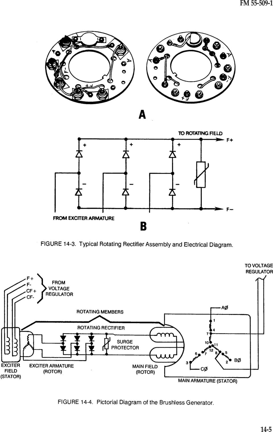
1 CHAPTER 14 SHIP SERVICE GENERATORS (AC) INTRODUCTION All generators change mechanical energy into electrical energy. This is the easiest way to transfer power over distances. Fuel is used to operate the diesel or prime mover. The fuel is converted into energy to turn the generator. The generator s movement, magnetic field, and associated wiring change this mechanical energy into electrical energy. Wires and cables deliver this power to the electrical loads. The motor is designed to change electrical energy back into mechanical energy to do work. Chapter 13 describes the rectified AC generator which produced a DC output to operate small DC electrical systems. This chapter describes the three-phase AC brushless generator which delivers three-phase AC to the ship s main electrical distribution system. Most of the large generators used to provide AC to ships electrical systems are of the brushless type. The brushless generator eliminates the weak link (brushes and slip rings) in the generating system and reduces the maintenance required. There are revolving field and revolving armature brush and slip ring generators in use today. However, brushless AC generators are used exclusively as the Army s ship service power source. BRUSHLESS ALTERNATING CURRENT GENERATOR CONSTRUCTION Figure 14-2 illustrates the brushless generator. The main frame or housing (7) is a strong metallic structure surrounding and retaining the stationary windings (6). The main frame is, in turn, supported by mounts. These mounts are not rigid. Rubber composition or springs are incorporated into the mounts as shock absorbers called resilient mounts. One end of the generator main frame is bolted to the prime mover s flywheel housing. The other end of the generator main frame is bolted to the bell end or end frame (12). The bell end contains a bearing (17) that supports the internal rotor shaft. The other end of the rotor shaft connects to a flexible drive disc (29) and fan (15) assembly. The drive disc assembly, in turn, is bolted to the flywheel of the prime mover. When the prime mover turns, the drive disc turns, and the fan pulls cooling air into the housing to dissipate heat created in the generator windings. The fan can disturb high bilge water and pass particulate of oil over the windings. When oilcovered windings become incapable of transferring sufficient heat to the air stream, the winding insulation becomes damaged. It is imperative that low bilge levels be maintained, and the diesel air box ventilation exhausts away from the fan s air flow. Generator Windings There are four different sets of windings in the brushless generator (Figure 14-2). Two windings (6 and 10) are connected to the generator main frame, and two windings (8 and 9) are fitted to the rotor shaft. There are no direct mechanical electrical connections between the rotating and stationary windings of the generator. Winding Contamination Inspect the stationary and rotating winding periodically for cleanliness. The chief engineer or his appointed representative will supervise internal inspection of the ship service generator. Never inspect internal generator components while the prime mover is operating or the generator is connected to the switchboard bus. Always secure the prime mover fully and ensure other power sources, such as the emergency generator or shore power, cannot feed the generator being serviced. Textbook maintenance practices call for removal of dirt by vacuuming and removal of grease and oil through wiping with lint-free rags. These methods rarely serve the purpose intended. Contamination prevention is the key. Inspect the generator prime mover for gasket and seal leaks. Check 14-1

2 also adjacent piping and deck plates for liquids and particles. Once the windings become contaminated, there is no thorough and safe method to clean the generator windings on board the vessel. The only effective recourse requires the removal of the generator, its complete disassembly, chemical cleaning, and baking by the DS/GS maintenance activity. When contamination is found, use the megger to check the insulation values. Always disconnect the rotating rectifier, voltage regulator, and any other components that house semiconductors. Compare readings with the appropriate technical manual, with other known good generator readings, or against megger historical documentation. Exciter Field The exciter field is a stationary DC energized winding. This is the winding where the DC magnetic field is initially developed. Even before any voltage regulation takes place, a residual magnetic field exists in the poles. During voltage regulation, DC in the exciter field induces an EMF and resulting current flow in the exciter armature. This winding can be found mounted toward the bell end section of the generator. Exciter Armature The exciter armature is a three-conductor, three-phase rotating winding. The exciter armature is located directly inside the exciter stator. A threephase EMF is induced in the exciter armature as it rotates inside the fixed magnetic field of the exciter field. Together, the exciter field and exciter armature develop a three-phase AC. In effect, this is a rotating armature generator. This portion of the generator is used to provide the excitation necessary for the main field portion. The exciter field and armature operate in the same manner described in Chapter 13. The exciter portion is the generator that develops the power necessary to develop the magnetic field in the main generator portion. Since current is induced into the armature without the aid of wires, brushes and slip rings are eliminated. Rotating Rectifier The output developed from the exciter portion of the generator is AC. To produce the enhanced three-phase output from the main armature of the generator (necessary for the large power requirements of the distribution system), the main field must be provided a direct current source. To change (or rectify) the exciter portion output from AC to DC, the rotating rectifier is used. The rotating rectifier provides the same conversion of AC to DC as the diode combination discussed in Chapter 13 for the belt-driven alternator. Main Rotating Field The main rotating field (8 in Figure 14-2) can consist of four to eight individual coils or pole pieces keyed to the rotor shaft. The coils are connected in series and consist of only one wire. The direction that the wire is wound around the pole piece determines the magnitude polarity of each individual field coil. Rectified DC, from the rotating rectifier (11), develops the revolving magnetic field inside the main 14-2

3 field generator portion providing alternate fixed field polarities. Amortisseur or Damper Winding Embedded in the face of each main field pole piece is the Amortisseur or damper windings. These are necessary for generators that operate in parallel. These become very important when dealing with frequency. The frequency of an AC generator must not change. These damper windings prevent hunting during parallel operation. Damper windings are copper or aluminum conductors embedded just below the surface of the rotor. They are short-circuited at each end to allow currents to circulate so that a magnetic field can be produced to oppose any change in prime mover motion. Main Armature The main armature (6 in Figure 14-2 view B) is bolted to the inside of the main frame. There are three windings, each of which are spaced 120 mechanical and electrical degrees apart. They may be connected in either wye or delta configurations as required for the application. The main armature windings are connected directly to the electrical system through the switchboard. 14-3

4 BRUSHLESS ALTERNATING CURRENT GENERATOR OPERATION The brushes and slip rings used by many small generators become intense maintenance problems. This area is extremely prone to contamination. As the brush slides over the slip ring, a certain amount of arcing may take place. To eliminate brushes, two generators are coupled together in a single housing. A rectified rotating armature generator, similar to the one discussed in Chapter 13, provides a direct current source for the rotating field of the main generator. Putting these two generators together eliminates the need for any physical mechanical connection between the moving and the stationary parts of the generator. Figure 14-4 is a pictorial diagram of the electrical circuits in the generic brushless AC generator. Generator Residual Magnetism Residual magnetism exists in all ferrous metal that has had a current carried around it. In many generators, there is not enough material to provide a substantial residual magnetic field to use in creating an EMF. The ship service generator has a lot of metal. The material mass maintains enough of a residual magnetic field in the exciter field to induce an EMF in the exciter armature when there is motion. 14-4

5 14-5
6 Outline of Operation The following is a basic outline of the brushless generator operation: The prime mover starts. The prime mover crankshaft revolves, and the generator shaft is moving. This turns the exciter armature, the main field, and the rotating rectifier. The exciter initiates an EMF. The rotating exciter armature cuts the residual magnetic field left over in the exciter field pole pieces. A small EMF is induced in the wye-wound rotating exciter armature windings. The exciter portion of the machine operates as a revolving armature generator. Exciter AC is rectified to DC. The small exciter three-phase AC is directed to the rotating rectifier. The diodes rectify the AC to a pulsating DC. Five wires are connected to the rotating rectifier. Three wires are from the three-phase exciter armature, and two wires direct the DC output to the main field winding. The main field induces an EMF into the main armature. Direct current enters the rotating main field. As the rotor shaft turns the main field, the alternating polarities induce an EMF of alternating potentials in the main armature windings. Three-phase AC is produced from the main armature. The main armature has three windings producing three-phase AC. The main portion of the generator is operating as a revolving field generator. Initially, only a small three-phase EMF is produced. Voltage control takes over. The voltage regulator senses an undervoltage condition and diverts the current flow back to the stationary exciter field. In this case, the CF exciter field winding is used for the initial voltage buildup and some shortcircuited conditions. The current flow through the exciter field winding increases its magnetic field. The exciter armature conductors now cut through a greater magnetic field, and the induced EMF in the exciter armature is increased. The process is repeated until satisfactory voltage is achieved. The increased exciter armature current is rectified by the rotating rectifier and directed again to the rotating main field. The increased magnetic field, of the rotating main field, sweeps past the conductors in the stationary main armature. This produces a greater three-phase EMF. Normal voltage control is maintained by the regulator controlling current to the exciter field. Permanent Magnet Generator (PMG) Newer Army generators employ six separate windings. The additional two windings are identical in operation to any pair of field and armature windings described above. These extra windings provide external excitation for the generator in the same way the four winding generator provided for its own self-excitation. On Cummins generators and some Caterpillar generators, a permanent magnet generator has been added to the generator assembly. The magnet is mounted on the rotor and is located inside the permanent magnet armature. When the generator is running, the PMG magnet generates an EMF in the PMG armature, providing current directly to the automatic voltage regulator for control of the exciter field. The permanent magnet provides definite voltage output on start-up and greater voltage control under extreme load conditions. GENERATOR VOLTAGE CONTROL The voltage regulator (Figure 14-5) controls the output of the generator by controlling the magnetic field in the stationary exciter field winding. The voltage regulator senses the generator s output voltage directly from the generator s main armature windings or indirectly through generator cable connections within the switchboard. The voltage regulator may monitor only a portion of the single phase (Figure 14-6) from the main armature s threephase or each phase directly from the switchboard. 14-6

7 The generator output voltage is controlled by controlling the current in the exciter field windings. Self-excited generators redirect part of their main armature AC output to the voltage regulator. Inside the voltage regulator, the armature AC is rectified to DC. The voltage regulator applies the DC to the exciter field to increase or decrease the magnetic field. When the exciter field magnetic strength is great, the generator s output is improved. With a decrease in the exciter field strength, the output of the generator is reduced. Separately excited generators sense the output voltage in the same manner as self-excited generators but derive the current for exciter field control directly from a permanent magnet generator designed exclusively for that purpose. In each case, changes in the magnetic exciter field strength is derived from DC supplied from the voltage regulator. FLASHING THE FIELD Initially, self-excited ship service generators may need to have the fields flashed to establish the 14-7

8 residual magnetism necessary to start the exciter induction process. NOTE: Read the manufacturer s recommendations carefully. Damage to the generator or voltage regulator will result if proper procedures are not correctly followed. Generally, flashing the field is done by connecting a battery to the exciter field terminals. By allowing directing current to flow through the exciter field windings, a residual magnetic field is established. The direct current source must be connected correctly. Failure to do so can damage the voltage regulator semiconductors. Observe the field and battery polarity. Ensure the connections are positive to positive and negative to negative. MAIN ARMATURE THREE-PHASE CONNECTIONS Brushless generators are usually 240- or 450- volt three-phase AC machines. They are rated in kva at a specified power factor. Many generator manufacturers produce a basic unit with a variety of voltage and current possibilities. The main armature consists of six individual windings. Two windings, as a pair, are connected to each other in series or parallel. Each armature winding pair is then connected to the other two armature winding pairs to form the common wye or delta combination. The actual connection between each winding is completed outside of the generator s frame in the attached terminal connector box. In this manner, the user can connect the individual armature winding pairs in series or parallel and the pairs in the delta or wye configuration. The configuration is selected for the type of voltage and current requirements that best fit the application. PHASES Only a single-phase EMF (voltage) can be induced (produced) in a single pair of the armature windings. Since there are three such pairs of windings, three separate single-phase EMF values are induced. It is the development of each of the three single-phase values that together produce the three-phase output from the armature windings (Figure 14-7). Phases are often referred to in the following manners: Three-phase: phase to phase to phase, A-B-C. Single-phase high voltage: phase to phase, A-B, B-C, A-C. Single-phase low voltage: phase to neutral, A-N, B-N, or C-N. Single-phase connections using the neutral are the least common combination on commercial or Army watercraft. The neutral connection is eliminated on all Army watercraft ship service generators but retained on some three-phase delta-wyeconnected transformers. Figure 14-8 illustrates the three-phase winding combination of the wye-connected armature. 14-8

9 A to B, B to C, C to A, A to N, B to N, C to N, or terminals A, B, and C (Figure 14-10). The electrical value found between any two terminals is a single-phase event. The electrical value found between three terminals is a three-phase event. There cannot be a two-phase value derived from these terminals. The single-phase circuit has an electrical load between two of the generator terminals. This is the only way to provide for the complete circuit required for current flow. The armature winding has the difference in potential required to attract the electron back. For example, terminals A and B complete one phase. The three-phase condition is the culmination of all the windings, A-B-C. This produces the highest voltage and current for a given period of time in the electrical system. The three-phase condition takes advantage of three independent electrical circuits almost simultaneously. Figure 14-9 shows how one circuit (between the generator armature and the motor stator windings) at a time is completed. Armature windings A to B and the motor s equivalent A (T1) to B (T2) windings complete one circuit (view A). After 120 degrees of generator rotor rotation, the B to C circuit starts (view B) in the same manner as the A to B circuit; 240 rotor degrees after the A to B circuit started, the C to A circuit is starting (view C). In effect, three single-phase currents are delivered to three motor windings in various amplitudes over the same period of time. NOTE: For clarity, three different periods of time are used to reflect a current at a maximum amplitude in one specific direction per completed circuit. In reality, current is moving in various amplitudes and directions at any point in time as illustrated by the three-phase sine wave. A phase is the reoccurring electrical event, or value, found between any combination of the generator s armature terminals. In other words, a phase is the voltage and current found between terminals The three-phase circuit uses three such combinations in varying amplitudes at the same time (Figure 14-11). Although each sine wave is usually identified as A, B, or C, each sine wave is a combination of a completed circuit. A better representation of the three-phase sine waves would identify each wave as the circuit it completes, such as A-B, B-C, or C-A. In this manner, it is easy to see the three single phases, operating out of phase by 120 electrical and mechanical degrees. It also becomes apparent that with the loss of anyone winding (A for example), only one complete circuit phase is left. Without phase A, there cannot be a completed circuit between A-B or C-A. This leaves only B-C and a single-phase event. This electrical three-phase malfunction is called single phasing. The following terms describe the operation of the generator and the transformer: Phase to phase to phase. This is a threephase event using all the available voltage and current values in the entire generator armature over a period of time. Phase to phase. This is a single-phase event, providing the total available voltage and current value from two individual phases. This is a high voltage single phase. There is no difference in voltage between phase-phase and phase-phase-phase values in the same machine. Phase to neutral. This is a single-phase event using any voltage and current that can be induced into one armature winding alone. This is a low voltage single-phase value. 14-9

10 14-10

11 and provides four leads and an extra low voltage capability. Whether windings are connected in an armature, in a single three-phase transformer, or in three single-phase transformers, the wye and delta combinations all apply equally. WYE-CONNECTED ARMATURE WINDING COMBINATIONS The generator main armature has six individual windings (Figure 14-12). Two windings are for use in each phase-to-neutral combination. Each of the two leads from each winding may be brought out of the armature to a connection box for connecting externally. How these windings are wired together will determine the current and voltage characteristics of the generator output terminals. Although this chapter deals primarily with ship service operations, the combinations of windings remain pertinent to transformers and motors alike. The neutral is used as a reference point when dealing with the Army s AC generators. Currently, the neutral is isolated within the connector box and left unconnected. However, it is necessary to understand the neutral conductor and its effects on the electrical system. The LSV uses the neutral lead from delta-wye transformers. The transformer s primary side receives three conductors from the generator armature. The secondary side of the LSV three-phase transformer uses the neutral terminal Marine generators are almost exclusively wyeconnected. The wye is a series winding because any completed circuit, A-B, B-C, or C-A, has only one path for current to flow. The neutral (N) represents the common connection point where one end of each of the individual phase windings are connected. The other end of the phase windings deliver power to the electrical system as terminals: A, B, or C. In the wye armature (Figure 14-13), the series connection is the key to the voltage and current output. If each phase winding can develop a specific number of amperes and volts, then the generator s total output characteristics can be calculated. For example, the phase winding A-N, B-N, or C-N can develop an induced EMF at 260 volts with a maximum resulting current of 100 amperes. Basic series circuit rules apply. In a series circuit, amperage remains constant. Therefore, current available to the electrical system from any phaseto-phase combination, A-B, B-C, or C-A, is 100 amperes. Line current = phase current = 100 amperes Phase-to-phase (or line) voltage, as described in the series circuit rules, is the sum of the individual phase winding voltages. In this case, 14-11

12 260 volts from A-N, for example, cannot be added to 260 volts from B-N because the same magnetic flux of the generator s main field does not affect them equally. The phase windings are displaced in time and space by 120 degrees. Instead, a constant has been developed through vector mathematics as This figure will always hold true for basic electrical needs. Figure shows the connection between voltage in a series circuit and the multiplication factor. The total voltage in a series circuit equals the sum of the voltages. However, Figure shows that the north magnetic polarity is influencing one armature winding in its entirety. The second overlapping armature winding is being affected to a great extent, but not fully. The third overlapping armature winding is not affected at all by the north field pole polarity. The magnetic influence of the single pole cannot affect each physically displaced winding equally. Think of the multiplication factor as the following: Voltage total = one complete armature winding + NOTE: This is an oversimplification 73 percent of the other armature winding of the entire electrical process. These armature winding effects happen to Et = 260 volts + (.73)(260 volts) all three windings by two different polarities constantly in various degrees Et = 260 volts volts (approximate) at any given time. Et = 450 volts 14-12

13 Multiplying the voltage by gives the voltage supplied to the electrical system by phase A-B (or B-C or C-A): (Phase-to-neutral voltage) x (1.732) = line voltage (260 volts) X (1.732) = 450 volts Should an additional single-phase voltage value be desired, the wye can be tapped at the neutral connection. This provides the phase-toneutral voltage. In this case, A-N, B-N, or C-N would provide another voltage value possibility of 260 volts (Figure 14-15). The same example values that were used with the wye-connected windings are used for the delta. Each phase winding can develop an induced EMF of 260 volts with a maximum current value of 100 amperes (Figure 14-18). The basic parallel rule states that voltage remains constant. Therefore Line voltage = phase voltage = 260 volts DELTA-CONNECTED ARMATURE The delta connects the windings in parallel (Figure 14-16). The positive end of each winding is connected to the negative end of another winding. The terminals are labeled A, B, and C. The delta connection in Figure shows that a complete circuit between any phase provides two paths for current to flow. For example, current may leave armature terminal A, go through the motor stator, and return to armature terminal B to complete the A-B circuit). The current in the C-A and the B-C phases are also affected by the rotor field in various degrees. Notice that there is no single common connection. All phases in the armature are connected together in parallel during any single-phase complete circuit. The parallel circuit rules, therefore, are the key to understanding the delta connection. Line current is the sum of the individual currents developed in the generator. Since the magnetic field of the rotor cannot affect all the phase windings equally, the constant must be used for the calculations. Line current = (phase current) x (1.732) Line current = (100 amps) x (1.732) Line current = 173 amperes POWER CONSIDERATIONS Both the wye- and the delta-wound generator have approximately the same power capability. The wye generator is the most favorable generator for the application. By using the higher voltage and lower current (450 volts and 100 amperes), smaller diameter conductors, contacts, and circuit breakers can be used in the electrical system. Dual voltage motors will run cooler and last longer with the lower current value

14 The delta generator uses 260 volts at 173 amperes to provide the same power needs to the electrical distribution system. Increased current means increased heat. Heat is the element of destruction to electrical components. The increase in current requires increased cable, contactor, and motor protective size. Any increase in size is an increase in cost. WYE-DELTA VOLTAGES When using identical windings, the high delta is the same voltage as the low wye and half the voltage of the high wye (Table 14-1). The parallel delta is half the voltage of the high delta and low wye and onefourth the voltage of the high wye. Figure details some of the possible configurations for wiring ship service generators. The many options let the manufacturer keep costs low by reducing the number of different generators that must be built and stocked. This lets the consumer determine what application of the generator best serves him

15 14-15

16 GENERATOR PHASE BALANCE The ship s distribution system has been specifically designed with certain conditions in mind. Your specific involvement with the actual design is unlikely. However, the marine engineer s direct influence on the electrical system is evident on each vessel. The Army requires that all the military inventory in its possession be maintained by configuration control standards. This means that all equipment will not be modified, added to, or altered in any manner without the proper approval of appropriate commands. Phase-to-neutral, phase-to-phase, and threephase relationships were discussed earlier. A vessel is designed to accommodate electrical growth of approximately 10 percent. When three-phase equipment is added to the distribution system, within the system s capabilities, few problems are encountered. The three-phase motor current draw is distributed over all three generator armature phases equally. There is no unbalanced condition. However, if a single-phase device is added to the distribution system, an additional electrical load will be imposed on one phase of the generator s armature only. The lowered resistance, from another resistance in parallel, means that more current will be delivered by the generator s armature phase that is involved. This also creates a voltage drop due to the internal resistance within that generator phase and increases the inductive reactance within that phase. This unbalances the generator. If too many single-phase loads are added to the same generator armature phase, overheating will occur. Moreover, if three-phase equipment is improperly replaced with a single-phase component, the entire generator overall three-phase current demand is reduced and replaced by an equal current demand on one phase alone. This is extremely detrimental to the generator. Generators function adequately within certain parameters of electrical imbalance. However, this is not for the marine engineer to determine. Any changes must be submitted in writing through the vessel maintenance office. Changes and additions to the electrical system, both approved and expedient, must be logged in the engineering logbook indicating the circuit, the phases involved, and the starting kva if the component is a motor. Every time you turn on a blender in the galley, turn your bunk lights off, or start the coffee pot, a single-phase circuit has been individually changed. These changes are considered and taken into account when the distribution system is designed. Improper component substitutions and unauthorized additions and modifications have not been considered in the design of the electrical system. FREQUENCY The frequency of a generator must never change. If the frequency of the generator changes, the speed of the motors and the contactor operation will be adversely affected. Frequency is measured in cycles per second or hertz. The equipment on board Army vessels operates at a frequency of 60 hertz. Frequency is concerned with how frequently the rotor s magnetic field sweeps past the armature winding and induces a usable EMF. Each time a north and south pair of poles rotates one complete revolution, one cycle of AC is developed. If a rotor 14-16

17 with one north and one south pole, called a two-pole machine, is revolved 60 times a second, it will produce a frequency of 60 hertz (cycles per second). Rotor revolutions, however, are not measured in cycles per second They are measured in revolutions per minute (RPM). Prime mover speed is an important factor in frequency. The other factor is generator construction. Generators are classified by the number of poles. For example, a two-pole generator has one pair of main field poles. A north and south pole constitute a pair. They are connected to the rotor shaft. A four-pole generator has two pairs of poles on the rotor and two pairs of poles in each phase in the armature. The number of poles determines the speed the prime mover must turn the rotor to maintain a frequency of 60 hertz. A four-pole generator must have a prime mover turn the rotor at 1,800 RPM to attain a frequency of 60 hertz (cycles per second). Frequency = (number of poles) x (RPM) (2 poles per pair*) x (6O seconds per minute**) Frequency = (4 poles) x (1,800 RPM) (2 poles per pair*) x (60 seconds per minute**) Frequency = 7, Frequency = 60 revolutions (or cycles) per second *2 poles per pair is a constant used to account for the requirement of two poles of one north and one south polarity for each individual cycle of events. **6O seconds per minute is a constant used to convert events per minute to cycles per second. Poles and Frequency Relationships Table 14-2 lists some of the more common speed and rotor pole relationships of the AC generator for 60 hertz operation. Factors Affecting Frequency When a large conductor motor is first started (connected to the line), the resistance of the distribution system is reduced. This reduction in resistance is because the loads in the distribution system are connected in parallel (Rt is always less than the smallest resistance in a parallel circuit). As distribution system resistance decreases, current from the generator increases through the main armature windings. This results in the following braking action Within the generator: Large main armature currents react with an increased main field magnetic flux (initiated by the voltage regulator to maintain voltage as the high current moves through the main armature windings to the load). Both strong magnetic fields, produced by increased current flow through the windings, slow the rotation of the generator shaft just as effectively as if a friction brake is applied. A form of this, known as electric braking, is commonly used in large motors to bring rotation to a rapid halt. The magnetic braking effect makes generator rotation by the prime mover most difficult. To help the prime mover overcome this difficulty, several components are used: The diesel governor maintains precise engine speed control. The diesel flywheel has stored energy which tends to keep the diesel moving at the same speed

18 The damper windings are required for all generators that operate in parallel. These damper windings are shortcircuited bars embedded in the main field (rotor) windings. Damper Winding Construction Figure view A shows the damper windings. These windings are nothing more than metal bars parallel to the rotor shaft (view B). The forward ends of these bars are connected together by shorting rings. The aft ends of these bars are connected in a like manner. When the magnetic fields from the main field and the main armature change in respect to each other, an EMF is induced in the damper bars. A resulting current flows, and a magnetic field is established because the bars are short-circuited at each end. The magnetic field that develops in the damper windings is a result of any change in the magnetic flux between the field and the armature windings. The magnetic field in the damper windings opposes the effects that created it. Damper Winding Operation When the rotor is turning at the required speed and there is no change in the current demands on the generator armature, then the rotor field, induced armature field, and the damper windings all move together. The two fields and the damper windings are magnetically linked together. However, there is no relative movement between them and no induced EMF in the damper windings. If the prime mover changes speed, resulting in a speed change of the rotor, there is a change in the magnetic field link between the rotor field, the induced armature field, and the short-circuited damper windings. This provides a relative motion between the magnetic fields and the damper windings. A voltage is induced with a resulting current flow in the damper windings. This current flow sets up its own magnetic field. This magnetic field is governed by the property of induction and Lenz s Law, which states, "An induced effect is always such as to oppose the cause that produced it." 14-18

19 This means that the speed decrease of the rotor is opposed magnetically by the damper windings. The magnetic field of the damper windings tries to push the rotor along and maintain speed. If the rotor would speed up, the induced EMF in the damper windings would develop a magnetic field that would oppose this speed increase, slowing the rotor to its original speed. VOLTAGE VARIATIONS UNDER LOAD When the generator is disconnected from the electrical system, no load is applied. Then the terminal voltage is exactly the same as the generated voltage. There is no current flow without a complete circuit. When the electrical circuit is completed and current flow is established in the armature, then certain phenomena take place. This is called the internal impedance of the generator. These factors affect the terminal voltage of the generator. Resistance of the Armature Conductors This is the IR drop so often mentioned. As current flows through the wire in the armature, it encounters resistance. The resistance of copper increases as its temperature increases. Any time current encounters resistance, a certain amount of force is necessary to overcome this resistance. The force that is used is voltage. Voltage is lost driving current through the armature windings of the generator. Although this voltage drop is small because of the small resistance encountered, the terminal voltage decreases as the current increases in response to the electrical system demands. The higher the current through the armature winding resistance, the greater the voltage consumed. lagging power factor and decreases terminal voltage. This is extremely common to Army watercraft. When current leads voltage out of the armature conductors (because of capacitor banks and synchronous motors), then a leading power factor develops. The armature current flow actually strengthens the magnetic field across the air gap and combines with the rotor field. This increases terminal voltage. Inductive Reactance This is encountered when an EMF is induced in a conductor. Induction produces a counter EMF. The current moving through the conductor and the magnetic fields cutting the adjacent turns of the conductor are all that is necessary to produce an EMF in the opposite direction. Inductive reactance in the armature may be as great as 30 to 50 times that of armature resistance. Two effects can be encountered with inductive reactance: When the load current is in phase with the terminal voltage or when the load current lags the terminal voltage (due to inductive reactance from motor loads), then additional voltage must be generated to overcome the armature s inductive reactance (Figure 14-21). Armature Reaction This is the combined effects of the rotor s magnetic field and the field developed in the armature as current is delivered to the electrical system. As long as the generator is not supplying current to the electrical system, the rotor s field is distributed evenly across the air gap to the main armature. When the generator supplies inductive loads, the current developed in the armature opposes the rotor s field and weakens it. This develops the When the current leads the terminal voltage, as is the case with capacitors or synchronous motors, then the inductive reactance in the armature aids the generated voltage. Less voltage must be generated than when resistance was the only consideration (Figure 14-22)

20 The effective value is also called the root mean squared (RMS) value. Mathematically, it is determined to be a factor of.707 of the peak value. POWER FACTOR VOLTAGE REGULATION The voltage regulation of an AC generator is the change of voltage from full load to no load, expressed in percentage of full-load volts. This information is necessary to determine how much change to expect in the terminal voltage between no load and full load. The DC generator output can be measured easily in watts. To calculate DC power, multiply the current by the voltage (review Power in Chapter 2). Unlike DC, AC does not maintain a constant amplitude. Further, the current and voltage are influenced by the very nature of the reversing current flow characterized by AC (Figure 14-23). To understand how these circumstances affect the actual generator output, the actual values available at the generator terminals must be understood. Percent regulation = (no-load volts) - (full-load volts) x 100 (full-load volts) Percent regulation = 465 volts volts x volts Percent regulation = 3.33 percent EFFECTIVE ALTERNATING CURRENT VALUES Voltage and current are often expressed in specific values. Alternating current changes not only in direction, but in constantly changing amplitudes. The value most commonly expressed is the generator s effective value. For instance, the 450-volt AC generator produces a 450-volt output with the same effect as the 450-volt DC generator. The effective value of the voltage or current is computed as follows: Square the instantaneous values. Determine the mean average. Extract the square root. Inductance was discussed in Chapter 6. Every motor, generator, and transformer has a coil of wire called an inductor. By the very nature of AC and its effects on the inductors in the circuit, current often lags voltage. The average current lag is represented by a decimal known as the power factor (PF). Unity power factor indicates that current and voltage arrive together and are in phase with each other. Unity power factor has a decimal representation of 1.0. Unity is the best use of electrical power. This condition results when all the power is consumed in the circuit. The ratio of unity to current lag is approximately 80 percent or.8 PF. The inductors in the motors actually become their own miniature generators, inducing an EMF that opposes a change in current. The current from the generator must overcome the resistance in the wires of the motor as well as 14-20
. Unlike DC, AC does not maintain a constant amplitude.")
21 overcome this counter EMF. The extra current developed by the generator, necessary to overcome the CEMF, is not consumed by the motor. It is considered to be a shuttle power, existing in the electrical system moving between the generator and the motor. This condition also results between two generators when they are improperly paralleled. When AC is applied only to resistors, lights, and heaters, all the power is consumed in the circuit. The power consumed in the resistive AC circuit can be computed the same as in the DC system. This is the true power (or active power) that has been consumed and is expressed in kilowatts (KW). Figure view A shows that the current and voltage rise and fall together. Only when the peak current and voltage are in phase is the product of voltage and amperage the same as the power consumption of the load in watts. This situation is inconceivable on board a vessel. The current held momentarily suspended in time by the CEMF generated by the action of the inductive coils cannot be successfully multiplied together to determine the power consumption of the electrical system. In view B, the current is delayed behind the voltage. The apparent power (power that the generator apparently sees that must be added to compensate) is represented by kva. Power factor is the percentage of the true power to apparent power or PF = KW (true power) kva (apparent power) PF = 125 KW 156 kva PF =.80 The electrical system must be designed to operate on the apparent power of the system, not the true power of the system. Apparent power is always greater than true power when there is a power factor less than 1.0 (unity). The following are some additional formulas that may be useful: (Three-phase applications) KW= (1.732) x E x I x PF 1,000 kva = (1.732) x E x I 1,000 HP= (1.732 x E x I x 100 x PF 746 x efficiency RPM = 2 x 60 x frequency poles 14-21
DIRECT CURRENT GENERATORS
 DIRECT CURRENT GENERATORS Revision 12:50 14 Nov 05 INTRODUCTION A generator is a machine that converts mechanical energy into electrical energy by using the principle of magnetic induction. This principle
Understanding the Alternator
 http://www.autoshop101.com THIS AUTOMOTIVE SERIES ON ALTERNATORS HAS BEEN DEVELOPED BY KEVIN R. SULLIVAN PROFESSOR OF AUTOMOTIVE TECHNOLOGY AT SKYLINE COLLEGE SAN BRUNO, CALIFORNIA ALL RIGHTS RESERVED
Motor Fundamentals. DC Motor
 Motor Fundamentals Before we can examine the function of a drive, we must understand the basic operation of the motor. It is used to convert the electrical energy, supplied by the controller, to mechanical
2. A conductor of length 2m moves at 4m/s at 30 to a uniform magnetic field of 0.1T. Which one of the following gives the e.m.f. generated?
 Extra Questions - 2 1. A straight length of wire moves through a uniform magnetic field. The e.m.f. produced across the ends of the wire will be maximum if it moves: a) along the lines of magnetic flux
Basics of Electricity
 Basics of Electricity Generator Theory PJM State & Member Training Dept. PJM 2014 8/6/2013 Objectives The student will be able to: Describe the process of electromagnetic induction Identify the major components
SYNCHRONOUS MACHINES
 SYNCHRONOUS MACHINES The geometry of a synchronous machine is quite similar to that of the induction machine. The stator core and windings of a three-phase synchronous machine are practically identical
SECTION 4 ELECTRIC MOTORS UNIT 17: TYPES OF ELECTRIC MOTORS
 SECTION 4 ELECTRIC MOTORS UNIT 17: TYPES OF ELECTRIC MOTORS UNIT OBJECTIVES After studying this unit, the reader should be able to Describe the different types of open single-phase motors used to drive
Unit 33 Three-Phase Motors
 Unit 33 Three-Phase Motors Objectives: Discuss the operation of wound rotor motors. Discuss the operation of selsyn motors. Discuss the operation of synchronous motors. Determine the direction of rotation
VOLTAGE REGULATOR AND PARALLEL OPERATION
 VOLTAGE REGULATOR AND PARALLEL OPERATION Generator sets are operated in parallel to improve fuel economy and reliability of the power supply. Economy is improved with multiple paralleled generators by
Chen. Vibration Motor. Application note
 Vibration Motor Application note Yangyi Chen April 4 th, 2013 1 Table of Contents Pages Executive Summary ---------------------------------------------------------------------------------------- 1 1. Table
DC GENERATOR THEORY. LIST the three conditions necessary to induce a voltage into a conductor.
 DC Generators DC generators are widely used to produce a DC voltage. The amount of voltage produced depends on a variety of factors. EO 1.5 LIST the three conditions necessary to induce a voltage into
Single-Phase AC Synchronous Generator
 ST Series Single-Phase AC Synchronous Generator Instructions for Operation and Maintenance English to English translation by R.G. Keen, May 2004. ST Series of Single-Phase AC Synchronous Generators Description
AC Generators. Basic Generator
 AC Generators Basic Generator A basic generator consists of a magnetic field, an armature, slip rings, brushes and a resistive load. The magnetic field is usually an electromagnet. An armature is any number
Motor Protection Voltage Unbalance and Single-Phasing
 Motor Protection Voltage Unbalance and Single-Phasing Cooper Bussmann contributes the following information, which is an excerpt from their 190-page handbook SPD Selecting Protective Devices Based on the
Equipment: Power Supply, DAI, Wound rotor induction motor (8231), Electrodynamometer (8960), timing belt.
, Electrodynamometer (8960), timing belt.") Lab 13: Wound rotor induction motor. Objective: to examine the construction of a 3-phase wound rotor induction motor; to understand exciting current, synchronous speed and slip in this motor; to determine
Lab 13: Wound rotor induction motor. Objective: to examine the construction of a 3-phase wound rotor induction motor; to understand exciting current, synchronous speed and slip in this motor; to determine
Welcome to Linear Controls Quarterly Training
 Welcome to Linear Controls Quarterly Training Introduction to Power Generation Objectives Supply attendees with basic knowledge of power generators and voltage regulators and provide the fundamentals of
DHANALAKSHMI COLLEGE OF ENGINEERING DEPARTMENT OF ELECTRICAL AND ELECTRONICS ENGINEERING EE2302 - ELECTRICAL MACHINES II UNIT-I SYNCHRONOUS GENERATOR
 1 DHANALAKSHMI COLLEGE OF ENGINEERING DEPARTMENT OF ELECTRICAL AND ELECTRONICS ENGINEERING Constructional details Types of rotors EE2302 - ELECTRICAL MACHINES II UNIT-I SYNCHRONOUS GENERATOR PART A 1.
Induction Motor Theory
 PDHonline Course E176 (3 PDH) Induction Motor Theory Instructor: Jerry R. Bednarczyk, P.E. 2012 PDH Online PDH Center 5272 Meadow Estates Drive Fairfax, VA 22030-6658 Phone & Fax: 703-988-0088 www.pdhonline.org
Direct Current Motors
 Direct Current Motors DC MOTORS The DC machine can operate as a generator and as a motor. Chap 5. Electrical Machines by Wildi, 6 e Lecturer: R. Alba-Flores Alfred State College Spring 2008 When a DC machine
AC Generators and Motors
 AC Generators and Motors Course No: E03-008 Credit: 3 PDH A. Bhatia Continuing Education and Development, Inc. 9 Greyridge Farm Court Stony Point, NY 10980 P: (877) 322-5800 F: (877) 322-4774 [email protected]
Line Reactors and AC Drives
 Line Reactors and AC Drives Rockwell Automation Mequon Wisconsin Quite often, line and load reactors are installed on AC drives without a solid understanding of why or what the positive and negative consequences
8 Speed control of Induction Machines
 8 Speed control of Induction Machines We have seen the speed torque characteristic of the machine. In the stable region of operation in the motoring mode, the curve is rather steep and goes from zero torque
Synchronous motor. Type. Non-excited motors
 Synchronous motor A synchronous electric motor is an AC motor in which the rotation rate of the shaft is synchronized with the frequency of the AC supply current; the rotation period is exactly equal to
PS-6.2 Explain the factors that determine potential and kinetic energy and the transformation of one to the other.
 PS-6.1 Explain how the law of conservation of energy applies to the transformation of various forms of energy (including mechanical energy, electrical energy, chemical energy, light energy, sound energy,
ABB ! CAUTION. Type COQ Negative Sequence Generator Relay. (50/60 Hertz) 41-161J. Instruction Leaflet
 41-161J. Instruction Leaflet") ABB Instruction Leaflet 41-161J Effective: May 1997 Supersedes I.L. 41-161H Dated July 1984 ( ) Denotes Change Since Previous Issue Type COQ Negative Sequence Generator Relay (50/60 Hertz)! CAUTION Before
ABB Instruction Leaflet 41-161J Effective: May 1997 Supersedes I.L. 41-161H Dated July 1984 ( ) Denotes Change Since Previous Issue Type COQ Negative Sequence Generator Relay (50/60 Hertz)! CAUTION Before
Rotary Phase Converters
 FACTS from Ronk Electrical Industries, Inc. Bulletin 11981 Rotary Phase Converters ROTOVERTER Pat. No. 3,670,238 ROTO-CON Pat. No. 4,158,225 What are the ROTO-CON and ROTOVERTER power converters? The ROTO-CON
Three-phase AC circuits
 Three-phase AC circuits This worksheet and all related files are licensed under the Creative Commons Attribution License, version 1.0. To view a copy of this license, visit http://creativecommons.org/licenses/by/1.0/,
AC generator theory. Resources and methods for learning about these subjects (list a few here, in preparation for your research):
:") AC generator theory This worksheet and all related files are licensed under the Creative Commons Attribution License, version 1.0. To view a copy of this license, visit http://creativecommons.org/licenses/by/1.0/,
AC generator theory This worksheet and all related files are licensed under the Creative Commons Attribution License, version 1.0. To view a copy of this license, visit http://creativecommons.org/licenses/by/1.0/,
Equipment: Power Supply, DAI, Synchronous motor (8241), Electrodynamometer (8960), Tachometer, Timing belt.
, Electrodynamometer (8960), Tachometer, Timing belt.") Lab 9: Synchronous motor. Objective: to examine the design of a 3-phase synchronous motor; to learn how to connect it; to obtain its starting characteristic; to determine the full-load characteristic of
Lab 9: Synchronous motor. Objective: to examine the design of a 3-phase synchronous motor; to learn how to connect it; to obtain its starting characteristic; to determine the full-load characteristic of
13 ELECTRIC MOTORS. 13.1 Basic Relations
 13 ELECTRIC MOTORS Modern underwater vehicles and surface vessels are making increased use of electrical actuators, for all range of tasks including weaponry, control surfaces, and main propulsion. This
Three phase circuits
 Three phase circuits THREE PHASE CIRCUITS THREE-PHASE ADVANTAGES 1. The horsepower rating of three-phase motors and the kva rating of three-phase transformers are 150% greater than single-phase motors
Lab 14: 3-phase alternator.
 Lab 14: 3-phase alternator. Objective: to obtain the no-load saturation curve of the alternator; to determine the voltage regulation characteristic of the alternator with resistive, capacitive, and inductive
Digital Energy ITI. Instrument Transformer Basic Technical Information and Application
 g Digital Energy ITI Instrument Transformer Basic Technical Information and Application Table of Contents DEFINITIONS AND FUNCTIONS CONSTRUCTION FEATURES MAGNETIC CIRCUITS RATING AND RATIO CURRENT TRANSFORMER
SYNCHRONOUS MACHINE TESTING WITH MOTOR CIRCUIT ANALYSIS INSTRUMENTATION
 SYNCHRONOUS MACHINE TESTING WITH MOTOR CIRCUIT ANALYSIS INSTRUMENTATION Introduction Howard W. Penrose, Ph.D., CMRP Vice President, Engineering and Reliability Services Dreisilker Electric Motors, Inc.
Application Information
 Moog Components Group manufactures a comprehensive line of brush-type and brushless motors, as well as brushless controllers. The purpose of this document is to provide a guide for the selection and application
Principles of Adjustable Frequency Drives
 What is an Adjustable Frequency Drive? An adjustable frequency drive is a system for controlling the speed of an AC motor by controlling the frequency of the power supplied to the motor. A basic adjustable
Lab 8: DC generators: shunt, series, and compounded.
 Lab 8: DC generators: shunt, series, and compounded. Objective: to study the properties of DC generators under no-load and full-load conditions; to learn how to connect these generators; to obtain their
1. The diagram below represents magnetic lines of force within a region of space.
 1. The diagram below represents magnetic lines of force within a region of space. 4. In which diagram below is the magnetic flux density at point P greatest? (1) (3) (2) (4) The magnetic field is strongest
Equipment: Power Supply, DAI, Universal motor (8254), Electrodynamometer (8960), timing belt.
, Electrodynamometer (8960), timing belt.") Lab 12: The universal motor. Objective: to examine the construction of the universal motor; to determine its no-load and full-load characteristics while operating on AC; to determine its no-load and full-load
Lab 12: The universal motor. Objective: to examine the construction of the universal motor; to determine its no-load and full-load characteristics while operating on AC; to determine its no-load and full-load
ST Style Generator. Owners/Operators Manual
 ST Style Generator Owners/Operators Manual LLC 216 Airport Rd NE Milledgeville, GA 31061 478-453-9358-Office 478-457-5524- Tom Cell 478-251-2914- Chris Cell Table of Contents Page 2. Table of Contents
How To Understand And Understand The Electrical Power System
 DOE-HDBK-1011/4-92 JUNE 1992 DOE FUNDAMENTALS HANDBOOK ELECTRICAL SCIENCE Volume 4 of 4 U.S. Department of Energy Washington, D.C. 20585 FSC-6910 Distribution Statement A. Approved for public release;
Keywords: synchronous generator, synchronous motor, automatic voltage regulator, V- curves, synchronizing power, hunting, excitation system
 SYNCHRONOUS MACHINES Tze-Fun Chan Hong Kong Polytechnic University, Hong Kong, China Keywords: synchronous generator, synchronous motor, automatic voltage regulator, V- curves, synchronizing power, hunting,
Science and Reactor Fundamentals Electrical CNSC Technical Training Group. Table of Contents
 Electrical Science and Reactor Fundamentals Electrical i Table of Contents 1 Objectives... 1 1.1 BASIC ELECTRICAL THEORY... 1 1.2 TRANSFORMERS... 1 1.3 GENERATORS... 2 1.4 PROTECTION... 3 2 BASIC ELECTRICAL
UNIT 3 AUTOMOBILE ELECTRICAL SYSTEMS
 UNIT 3 AUTOMOBILE ELECTRICAL SYSTEMS Automobile Electrical Structure 3.1 Introduction Objectives 3.2 Ignition System 3.3 Requirement of an Ignition System 3.4 Types of Ignition 3.4.1 Battery or Coil Ignition
Introduction. Upon completion of Basics of AC Motors you should be able to:
 Table of Contents Introduction...2 AC Motors...4 Force and Motion...6 AC Motor Construction... 12 Magnetism... 17 Electromagnetism... 19 Developing a Rotating Magnetic Field...24 Rotor Rotation...29 Motor
FREQUENCY CONTROLLED AC MOTOR DRIVE
 FREQUENCY CONTROLLED AC MOTOR DRIVE 1.0 Features of Standard AC Motors The squirrel cage induction motor is the electrical motor motor type most widely used in industry. This leading position results mainly
The DC Motor/Generator Commutation Mystery. Commutation and Brushes. DC Machine Basics
 The DC Motor/Generator Commutation Mystery One small, yet vital piece of the DC electric motor puzzle is the carbon brush. Using the correct carbon brush is a key component for outstanding motor life,
Transformer Calculations
 Transformer Calculations Transformers Transformers are one of the most basic yet practical devices used today. No matter where you are there is always a transformer nearby. They are used throughout alternating-current
AC Electric Motors best practice
 If you want to learn more about best practice machinery maintenance, or world class mechanical equipment maintenance and installation practices, follow the link to our Online Store and see the Training
26 3213.13 Diesel Engine Driven Generators Page 1 of 6
 Last Update: December 8, 2014 A. Description of System Consultant s Handbook Page 1 of 6 1. Provide a diesel engine driven electric generating unit, factory assembled, tested and certified to operate at
Basic Electrical Technology Dr. L. Umanand Department of Electrical Engineering Indian Institute of Science, Bangalore. Lecture - 33 3 phase System 4
 Basic Electrical Technology Dr. L. Umanand Department of Electrical Engineering Indian Institute of Science, Bangalore Lecture - 33 3 phase System 4 Hello everybody. So, in the last class we have been
Motors and Generators
 Motors and Generators Electro-mechanical devices: convert electrical energy to mechanical motion/work and vice versa Operate on the coupling between currentcarrying conductors and magnetic fields Governed
Principles and Working of DC and AC machines
 BITS Pilani Dubai Campus Principles and Working of DC and AC machines Dr Jagadish Nayak Constructional features BITS Pilani Dubai Campus DC Generator A generator consists of a stationary portion called
AC-Synchronous Generator
 Design Description AC Generators come in two basic types synchronous and non-synchronous. Synchronous generators lock in with the fundamental line frequency and rotate at a synchronous speed related to
Specifying a Variable Frequency Drive s
 Specifying a Variable Frequency Drive s Put on by Bruce Reeves and Jeremy Gonzales Dykman Electrical Covering the Western US For all of your VFD and Soft Start and Motor Needs How To Specify a Variable
Lesson 3 DIRECT AND ALTERNATING CURRENTS. Task. The skills and knowledge taught in this lesson are common to all missile repairer tasks.
 Lesson 3 DIRECT AND ALTERNATING CURRENTS Task. The skills and knowledge taught in this lesson are common to all missile repairer tasks. Objectives. When you have completed this lesson, you should be able
How To Wire A Three Phase, Single Phase, Wye Transformer
 Three-Phase Transformers When more power is needed - three transformers can be tied together. This is called three-phase. Here s a simple way of comparing single-phase to threephase power. Single-Phase
AC Induction Motor Slip What It Is And How To Minimize It
 AC Induction Motor Slip What It Is And How To Minimize It Mauri Peltola, ABB Oy, Helsinki, Finland The alternating current (AC) induction motor is often referred to as the workhorse of the industry because
DC generator theory. Resources and methods for learning about these subjects (list a few here, in preparation for your research):
:") DC generator theory This worksheet and all related files are licensed under the Creative Commons Attribution License, version 1.0. To view a copy of this license, visit http://creativecommons.org/licenses/by/1.0/,
DC generator theory This worksheet and all related files are licensed under the Creative Commons Attribution License, version 1.0. To view a copy of this license, visit http://creativecommons.org/licenses/by/1.0/,
Voltage Unbalance and Motors
 Voltage Unbalance and Motors Background Voltage unbalance occurs when the RMS line voltages on a poly-phase system are unequal. Voltages are seldom perfectly balanced between phases, but when this unbalance
Generator Stator Protection, under/over voltage, under /over frequency and unbalanced loading. Ramandeep Kaur Aujla S.NO 250447392
 1 Generator Stator Protection, under/over voltage, under /over frequency and unbalanced loading By Ramandeep Kaur Aujla S.NO 250447392 ES 586b: Theory and applications of protective relays Department of
Chapter 12: Three Phase Circuits
 Chapter 12: Three Phase Circuits 12.1 What Is a Three Phase Circuit? 12.2 Balance Three Phase Voltages 12.3 Balance Three Phase Y to Y Connection 12.4 Other Balance Three Phase Connections 12.5 Power in
BALANCED THREE-PHASE CIRCUITS
 BALANCED THREE-PHASE CIRCUITS The voltages in the three-phase power system are produced by a synchronous generator (Chapter 6). In a balanced system, each of the three instantaneous voltages have equal
The following table shows approximate percentage wise the
 SHORT-CIRCUIT CALCULATION INTRODUCTION Designing an electrical system is easy and simple, if only the normal operation of the network is taken into consideration. However, abnormal conditions which are
AND8008/D. Solid State Control Solutions for Three Phase 1 HP Motor APPLICATION NOTE
 Solid State Control Solutions for Three Phase 1 HP Motor APPLICATION NOTE INTRODUCTION In all kinds of manufacturing, it is very common to have equipment that has three phase motors for doing different
Simple Analysis for Brushless DC Motors Case Study: Razor Scooter Wheel Motor
 Simple Analysis for Brushless DC Motors Case Study: Razor Scooter Wheel Motor At first glance, a brushless direct-current (BLDC) motor might seem more complicated than a permanent magnet brushed DC motor,
ElectroMagnetic Induction. AP Physics B
 ElectroMagnetic Induction AP Physics B What is E/M Induction? Electromagnetic Induction is the process of using magnetic fields to produce voltage, and in a complete circuit, a current. Michael Faraday
101 BASICS SERIES LEARNING MODULE 2: FUNDAMENTALS OF ELECTRICITY. Cutler-Hammer
 101 BASICS SERIES LEARNING MODULE 2: FUNDAMENTALS OF ELECTRICITY Cutler-Hammer WELCOME Welcome to Module 2, Fundamentals of Electricity. This module will cover the fundamentals of electricity in a practical
DC MOTOR ANALYSIS & TROUBLESHOOTING
 DC MOTOR ANALYSIS & TROUBLESHOOTING By Don Shaw Condition assessment of DC motors requires a basic understanding of the design and operating characteristics of the various types available: the series motor,
ELECTRICAL ENGINEERING Vol. III - Induction Motor and Self-Excited Induction Generator - Tze-Fun Chan
 INDUCTION MOTOR AND SELFEXCITED INDUCTION GENERATOR TzeFun Chan The Hong Kong Polytechnic University, Hung Hom, Kowloon, Hong Kong, China Keywords: threephase induction motor, singlephase induction motor,
BASIC ELECTRONICS AC CIRCUIT ANALYSIS. December 2011
 AM 5-202 BASIC ELECTRONICS AC CIRCUIT ANALYSIS December 2011 DISTRIBUTION RESTRICTION: Approved for Pubic Release. Distribution is unlimited. DEPARTMENT OF THE ARMY MILITARY AUXILIARY RADIO SYSTEM FORT
Aircraft Electrical System
 Chapter 9 Aircraft Electrical System Introduction The satisfactory performance of any modern aircraft depends to a very great degree on the continuing reliability of electrical systems and subsystems.
Table of Contents 1. Introduction 2. Electrical Fundamentals Electron Theory Matter 4 MOLECULE
 Table of Contents 1. Introduction 3 2. Electrical Fundamentals 4 Electron Theory 4 Matter 4 MOLECULE 5 The atom 6 Atom construction 7 Electrical charges 11 Balanced atoms 12 Ions 13 Electron orbits 15
ATTACHMENT F. Electric Utility Contact Information Utility Name. For Office Use Only
 ATTACHMENT F CATEGORY 2 GENERATOR INTERCONNECTION APPLICATION FOR ALL PROJECTS WITH AGGREGATE GENERATOR OUTPUT OF MORE THAN 20 KW BUT LESS THAN OR EQUAL TO 150 KW Also Serves as Application for Category
UCI274C - Technical Data Sheet
 - Technical Data Sheet SPECIFICATIONS & OPTIONS STANDARDS Newage Stamford industrial generators meet the requirements of BS EN 60034 and the relevant section of other international standards such as BS000,
Prof. Krishna Vasudevan, Prof. G. Sridhara Rao, Prof. P. Sasidhara Rao. x x. x x. Figure 10: Cross sectional view
 4 Armature Windings Main field Commutator & Brush Compole field haft v Compensating winding Armature winding Yoke Figure 10: Cross sectional view Fig. 10 gives the cross sectional view of a modern d.c.
PacifiCorp Original Sheet No. 476 FERC Electric Tariff, Substitute 6 th Rev Volume No. 11 APPENDIX 2 TO SGIP
 PacifiCorp Original Sheet No. 476 APPENDIX 2 TO SGIP SMALL GENERATOR INTERCONNECTION REQUEST (Application Form) Transmission Provider: Designated Contact Person: Address: Telephone Number: An Interconnection
PHASE CONVERSION TECHNOLOGY OVERVIEW
 Dr. Larry Meiners, Ph.D. PHASE CONVERSION TECHNOLOGY OVERVIEW Introduction A wide variety of commercial and industrial electrical equipment requires three-phase power. Electric utilities do not install
UCI274H - Technical Data Sheet
 - Technical Data Sheet SPECIFICATIONS & OPTIONS STANDARDS Newage Stamford industrial generators meet the requirements of BS EN 60034 and the relevant section of other international standards such as BS000,
FAULT FINDING MANUAL For Self Excited and Separately Excited Generators
 FAULT FINDING MANUAL For Self Excited and Separately Excited Generators SAFETY PRECAUTIONS Before testing the generating set, read the generating set Installation Manual, and this Fault Finding Manual,
Objectives. Capacitors 262 CHAPTER 5 ENERGY
 Objectives Describe a capacitor. Explain how a capacitor stores energy. Define capacitance. Calculate the electrical energy stored in a capacitor. Describe an inductor. Explain how an inductor stores energy.
Power Plant Electrical Distribution Systems
 PDH Course E184 Power Plant Electrical Distribution Systems Gary W Castleberry, PE 2008 PDH Center 2410 Dakota Lakes Drive Herndon, VA 20171-2995 Phone: 703-478-6833 Fax: 703-481-9535 www.pdhcenter.com
CAT AVR V2.3. Instruction Manual. Voltage regulator for generators. March 2008
 CAT AVR V2.3 Voltage regulator for generators March 2008 Instruction Manual Warnings WARNING The system should not be installed, operated, serviced or modified except by qualified personnel who understand
Understanding Generator Ripple Waveforms
 Understanding Generator Ripple Waveforms 2 Understanding Generator Ripple Waveforms Chapter Page Preliminary Information and Setup 3 Generator Theory 6 Generator Ripple Theory 15 Factors that Influence
Drive circuit basics + V. τ e. Industrial Circuits Application Note. Winding resistance and inductance
 ndustrial Circuits Application Note Drive circuit basics For a given size of a stepper motor, a limited space is available for the windings. n the process of optimizing a stepper motor drive system, an
GenTech Practice Questions
 GenTech Practice Questions Basic Electronics Test: This test will assess your knowledge of and ability to apply the principles of Basic Electronics. This test is comprised of 90 questions in the following
Variable Frequency Drives - a Comparison of VSI versus LCI Systems
 Variable Frequency Drives - a Comparison of VSI versus LCI Systems Introduction TMEIC is a leader in the innovative design and manufacture of large ac variable f requency drive systems. TMEIC has been
Short Circuit Current Calculations
 Introduction Several sections of the National Electrical Code relate to proper overcurrent protection. Safe and reliable application of overcurrent protective devices based on these sections mandate that
ELECTRONIC POWER SYSTEMS
 ELECTRONIC POWER SYSTEMS TRADEOFFS BETWEEN SINGLE-PHASE & THREE-PHASE POWER WHITE PAPER: TW0057 1 Executive Summary Modern Electronic Systems are quite often powered from a three-phase power source. While
Current Transformers
 Tyco Electronics Corporation Crompton Instruments 1610 Cobb International Parkway, Unit #4 Kennesaw, GA 30152 Tel. 770-425-8903 Fax. 770-423-7194 Current Transformers Current transformers (CT's) provide
Table of Contents. The Basics of Electricity 2. Using a Digital Multimeter 4. Testing Voltage 8. Testing Current 10. Testing Resistance 12
 Table of Contents The Basics of Electricity 2 Using a Digital Multimeter 4 IDEAL Digital Multimeters An Introduction The Basics of Digital Multimeters is designed to give you a fundamental knowledge of
Chapter 11. Inductors ISU EE. C.Y. Lee
 Chapter 11 Inductors Objectives Describe the basic structure and characteristics of an inductor Discuss various types of inductors Analyze series inductors Analyze parallel inductors Analyze inductive
Effective: September 10, 2006 Vermont Attachment 1 to Rule 5.500 Public Service Board Page 1 of 6
 Public Service Board Page 1 of 6 STANDARD APPLICATION FOR INTERCONNECTION OF GENERATION RESOURCES IN PARALLEL TO THE ELECTRIC SYSTEM OF: (Interconnecting Utility) Preamble and Instructions: An owner of
Module Title: Electrotechnology for Mech L7
 CORK INSTITUTE OF TECHNOLOGY INSTITIÚID TEICNEOLAÍOCHTA CHORCAÍ Autumn Examinations 2012 Module Title: Electrotechnology for Mech L7 Module Code: ELEC7007 School: School of Mechanical, Electrical and Process
Speed Control Methods of Various Types of Speed Control Motors. Kazuya SHIRAHATA
 Speed Control Methods of Various Types of Speed Control Motors Kazuya SHIRAHATA Oriental Motor Co., Ltd. offers a wide variety of speed control motors. Our speed control motor packages include the motor,
How To Balance Three Phase Power In A Balanced System
 Three-Phase Circuits Three-Phase Circuit Three-Phase Circuits What is a Three-Phase Circuit? Balance Three-Phase oltages Balance Three-Phase Connection Power in a Balanced System Unbalanced Three-Phase
Physical Address: City: State: Zip Code:
 Application for Small Generator Facility Interconnection Tier 2, Tier 3 or Tier 4 Interconnection (For Small Generator Facilities with Electric Nameplate Capacities of 10 MW and less) Applicant Contact
Introduction. Three-phase induction motors are the most common and frequently encountered machines in industry
 Induction Motors Introduction Three-phase induction motors are the most common and frequently encountered machines in industry - simple design, rugged, low-price, easy maintenance - wide range of power
Three-Phase Electric Power Distribution for Computer Data Centers
 Three-hase Electric ower Distribution for Computer Data Centers WHITE AER E901 Geist January 008 Summary This paper will describe the characteristics of three-phase power and outline the advantages of
WHITE PAPER. DC Motors Explained. DC Motors Explained: White Paper, Title Page
 DC Motors Explained: White Paper, Title Page DC Motors Explained By Joe Kimbrell, Product Manager, Drives, Motors & Motion, AutomationDirect DC Motors Explained: White Paper, pg. 2 How many types of DC