The following table shows approximate percentage wise the
|
|
|
- Sheena Norton
- 7 years ago
- Views:
Transcription
1 SHORT-CIRCUIT CALCULATION

2 INTRODUCTION Designing an electrical system is easy and simple, if only the normal operation of the network is taken into consideration. However, abnormal conditions which are likely to occur anytime must be foreseen and should be taken seriously during the design stage. A good design must not only be made simple, but most importantly, safe and reliable. An Electrical system must operate continuously during normal and healthy overload situations; its protective device must also trip expeditiously to isolate the affected parts of the system during fault conditions.

3 Why Fault Occur? Fault in power system occur because of insulation failure in plant which may be caused by a system over-voltage such as switching surge or a lightning stroke, or maybe due to broken insulators or conductors and various causes in the system. The following table shows approximate percentage wise the various causes of faults: (i) Lightning 6% (ii) Sleet, wind, Mechanical (jumping conductors) 10% (iii) Apparatus failure 10% (iv) Switching to a fault 10% (v) Miscellaneous (tree falling on lines, sabotage) 10%
 Lightning 6% (ii) Sleet, wind, Mechanical")
4 These faults can take one of the following forms: Type Probability of failures 1. Single phase to ground faults 10% 2. Phase to phase faults 15% 3. Two-phases to ground faults 10% 4. Three-phase faults 5% Such faults cause heavy currentscalled, short-circuit currents, to flow in the system. The determination of the values of such currents enables us to make proper selection of circuit breakers, protective relays and also helps to ensure that the associated apparatus e.g. bus bars, connections, current transformers will withstand the forces which arise due to the fault currents during the period prior to the interrupting device clearing the fault.

5 Single phase to ground faults are the most common whereas the three phase short-circuit fault are the most severe faults and also the most amenable to calculations since these involve symmetrical conditions only. For unsymmetrical ground faults, line-to-ground fault on a solidly grounded system is used to size ground cable as well as to coordinate ground fault protective devices. Sources of Fault Power. All the generating and trandformers which under normal conditions take power from the system. Synchronous Machines. Under short-circuit conditions, a drop in frequency or voltage is common and in this event, synchronous machineswillfeedbackintothesystemforashortperiod. Large Induction Motor. large induction motor s flywheel effect will act as generators in the event of reduces frequency. Where machines such as these are connected, and they are of size as to have effect particularly where they are connected to a point close to that for which short-circuit values are being calculated, they should be calculated. Frequency chargers

6 FAULT CURRENTS LIMITERS: Cables Busbars Circuit breakers, Reactors Transformer P Q x G. F 1 P Q G x F 1 x F 2 G x F 3 Fig short-circuit fed from a single generator Fig short-circuit fed from a source having more then one generator

7 In Fig.1.1, letpand Qrepresents the busbars at the power station and the sub-station respectively. Also F 1 represents a feeder outgoing from the sub-station bus-bars and equipped with circuit breaker at X. IfthereisasinglefeederconnectingPandQandthegeneratingstation also consists of a single generator as in Fig 1.1, in the event of fault occurringatanypointinonfeederf 1,theshort-circuitcurrentfromthe generating station will be a certain value limited by the impedance of thegeneratorandtheimpedanceofthefeederuptothepointoffault. Now supposed that an increased load is required to be fed from the sub-station bus-bars. In that case, it may become necessary to increase the generating units at the power station and also to install a second feeder between P and Q to carry the increased load. ( It is assumed that the original generating unit and feeder between P and Q were fully loaded). With the increased load, which may be due to additional consuming apparatus, it may be similarly necessary to have more outgoing feeders F 1 andf 2 etc.asshowninfig.1.2.

8 The fault current from the generating station due to a fault occurring on,sayf 1 willbegreaterthanthatintheoriginalsystemdueto (i) large kva of the generating plant, (ii) smaller impedance of the generating plant.( the equivalent impedance of two generators in parallel is smaller than the individual impedance of each.) (iii)thesmallerimpedanceofthetwofeedersconnectingpandq since they are now in parallel. The value of fault current which can flow in any system under shortcircuit is limited only by the impedance in that system. Therefore, it is necessary in any calculation to have knowledge of these impedances.
 (iii)thesmallerimpedanceofthetwofeedersconnectingpandq since they are now in parallel.")
9 Reactance. Often the resistance is so small that in most cases reactance alone is considered for calculating the fault currents. In general it is to be noted that if the reactance exceeds 3 times the resistance, the resistance may be neglected. The error in the assumption will not exceed 5%. The reactance of synchronous machines, transformers, reactors, is usually expressed as a percentage.

10 In electrical systems, power flows from the sources to loads through circuit components which has specific impedances. The power flow is principally determined by the load impedance. A FAULT can be described as a load with very low impedance. Depending upon the type of fault, Phase or ground faults can be regarded as Source Limited (phase fault) or Fault limited (ground faults). All the fault calculating methods are based upon this principle.
 or")
11 FAULTS CALCULATING METHODS: Ohms Method The basic formula for all current flow is Ohms Law, Volts = Ampere x Ohms. This is easily applied to single phase circuits operating at only one voltage level. However, when several different voltages occur, the situation becomes more complicated. Each location in the circuit where faults must be calculated has an specific operating voltage. All circuit impedances must be referred to the fault voltage before calculating the short-circuit current.

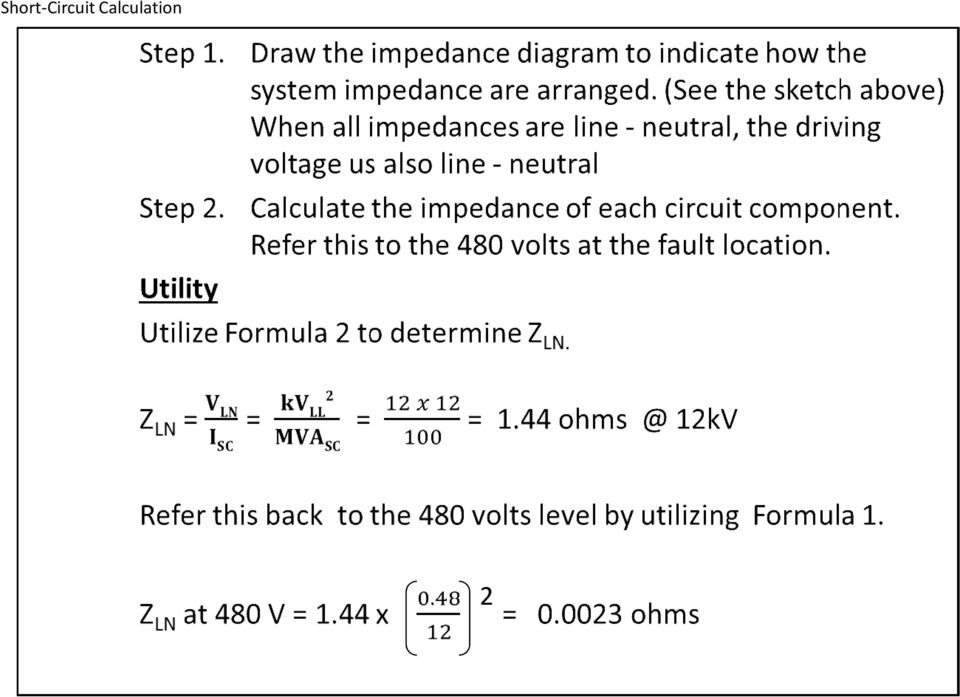
12 Formula 1 - is based for referring impedance to a new voltage at which the fault is being calculated. When all the impedances have been referred to the fault voltage, they can be added. New Voltage Ohms at new V = Ohms at old V x ( Formula 1) Old Voltage Example: Calculate the two faults indicated on the following diagram. 2

13 480 volts Fault 1 - I SC1 = = 96 Amps 5 ohms Fault 2 - refer 5 ohms from 480V to 240V 240 V 240V = 5 x = 5 x V= V Assume perfect transformer (Z = 0%) Total Impedance = = 4.25 ohms 240 volts Fault 2 - I SC2 = = 56.5 Amps 4.25 ohms 2

14

15 This conversion is necessary when a transformer must be included or motor contribution is being considered. The formula is derived from the fact that the impedance of the transformer or motor is the only limitation to the circulation of current with a winding shorted or rotor locked. The rating of voltage required to circulate full rated current to the rated voltage is the Per Unit Impedanceof the particular transformer of motor. Consider the following system consisting of a utility in-feed through the cable to a transformer. The step by step solution is shown below. Example:

16 2
17 2

18

19

20
21
22
23
24 (Formula 5) (Formula 6) (Formula 9)
25
26 The circuit used to illustrate the Ohmic calculations is used below to illustrate Per Unit calculations.
27
28
29 So far only three phase faults have been considered. In all cases, the fault impedance was assumed to be zero. However, three phase faults do not often occur. Ground faults are by far the most common and they generally have arc and contact impedance at the point of the fault. Impedance of the ground return path may also be an important factor. The fact that the ground faults are rarely bolted (near zero fault impedance), does not mean the case may be ignored. Bolted phase to ground faults are generally the theoretical worst case. For this reason it is necessary to calculate them and understand the theory behind the calculations. The study of ground faults necessarily leads us to symmetrical component analysis. The theory presented here is brief and no mathematical proof is included.
30 The bolted 3-phase faults which have been considered thus far were calculated with the assumption that all voltages and impedances were balanced, i.e., a symmetrical fault. When it becomes necessary to analyze an unsymmetrical fault (phase to phase, phase to ground, etc.) the calculations become quite complicated. To simplify the analytical process, the unbalanced system of vectors is reduced into three balanced vector systems which are known as POSITIVE, NEGATIVE, and ZERO phase sequence components. The positive sequence components consist of three vectors equal in magnitude, 120 degrees displaced and rotating ABC. The negative sequence components are three equal vectors, 120 degrees displaced and rotating ACB. The zero sequence components consists of three vectors equal in magnitude and in phase. Each of these sets of voltage vectors is shown in the following diagram.
31 Now that three sets of sequence voltages have been assumed, It follows that they are the result of sequence currents flowing through sequence impedances. Positive sequence currents only flow through positive sequence impedance, etc. It is then possible to draw an impedance diagram for each sequence in order to calculate faults. The Theory and generation of these diagrams is best described in applied Protective relaying references. It will simply be stated here that the impedance diagram is drawn and connected as shown in the following sketches.
32 IMPEDANCE DIAGRAM
33
34 Since delta-delta and delta-wye grounded transformers are most common, the equivalent diagram of each is shown below:
35
36 For most circuits, the positive and negative sequence impedances can be assumed equal. The zero sequence impedance will depend upon the location of delta windings in the circuit. The term Zn refers to impedance in the neutral or return path from the fault to the transformer neutral connection. Z f refers to the impedance of the fault arc. The example assumes Zn and Z f are zero, i.e., a bolted phase to ground fault.
37 Step 1. Draw the impedance diagram. Note that Z 0 only includes the transformer. Z 0 is assumed equal to Z 1. Step 2. The impedance of each system element has already been calculated in the 3-phase example. All of the following impedances have been referred to the 480 volts level. Utility = ohms (slide 16) Cable = ohms (slide 17) Transformer = ohms (slide 18)
38
39
40 Example: The basic form of the Ohmic impedance diagram is suitable for this example. Step 1. Draw the impedance diagram. Step 2. The impedance calculated for the 3-phase fault are valid for this condition. Utility Cable = 0.1 0/1 ohm = /1 ohm Transformer = 0.5 0/1 ohm Step 3. Calculate the total impedance. Z t1 = /1 ohm = Z t2 Z t2 = /1 ohm Z t0 = 0.5 0/1 ohm Z T = /1 ohm
41
SAMPLE OF THE STUDY MATERIAL PART OF CHAPTER 3. Symmetrical Components & Faults Calculations
 SAMPLE OF THE STUDY MATERIAL PART OF CHAPTER 3 3.0 Introduction Fortescue's work proves that an unbalanced system of 'n' related phasors can be resolved into 'n' systems of balanced phasors called the
1 Introduction. 2 The Symmetrical Component Transformation. J.L. Kirtley Jr.
 Massachusetts Institute of Technology Department of Electrical Engineering and Computer Science 6.06 Introduction to Power Systems Class Notes Chapter 4 Introduction To Symmetrical Components J.L. Kirtley
SPECIAL TOPICS ON GROUND FAULT PROTECTION AND PROTECTION COORDINATION IN INDUSTRIAL AND COMMERCIAL POWER SYSTEMS
 SPECIAL TOPICS ON GROUND FAULT PROTECTION AND PROTECTION COORDINATION IN INDUSTRIAL AND COMMERCIAL POWER SYSTEMS Claudio S. Mardegan claudio.mardegan@engepower.com www.engepower.com Phone: 55 3579-8777
LIMITING SHORT-CIRCUIT CURRENTS IN MEDIUM-VOLTAGE APPLICATIONS
 LIMITING SHORT-CIRCUIT CURRENTS IN MEDIUM-VOLTAGE APPLICATIONS Terence Hazel Senior Member IEEE Schneider Electric 38050 Grenoble France Abstract The power requirements for large industrial sites is increasing.
Motor Protection Voltage Unbalance and Single-Phasing
 Motor Protection Voltage Unbalance and Single-Phasing Cooper Bussmann contributes the following information, which is an excerpt from their 190-page handbook SPD Selecting Protective Devices Based on the
Simple Methods for Calculating Short Circuit Current Without a Computer By Dennis McKeown, PE GE Senior System Application Engineer
 Simple Methods for Calculating Short Circuit Current Without a Computer By Dennis McKeown, PE GE Senior System Application Engineer A Short Circuit analysis is used to determine the magnitude of short
Generator Stator Protection, under/over voltage, under /over frequency and unbalanced loading. Ramandeep Kaur Aujla S.NO 250447392
 1 Generator Stator Protection, under/over voltage, under /over frequency and unbalanced loading By Ramandeep Kaur Aujla S.NO 250447392 ES 586b: Theory and applications of protective relays Department of
Three phase circuits
 Three phase circuits THREE PHASE CIRCUITS THREE-PHASE ADVANTAGES 1. The horsepower rating of three-phase motors and the kva rating of three-phase transformers are 150% greater than single-phase motors
Short Circuit Current Calculations
 Introduction Several sections of the National Electrical Code relate to proper overcurrent protection. Safe and reliable application of overcurrent protective devices based on these sections mandate that
Electrical Fault Level Calculations Using the MVA Method
 J.M. PNG & SH PT LTD Chapter lectrical ault Level Calculations Using the Method 5 With modern day personal computers, hand calculations for electrical fault level are becoming a thing of the past. The
Digital Energy ITI. Instrument Transformer Basic Technical Information and Application
 g Digital Energy ITI Instrument Transformer Basic Technical Information and Application Table of Contents DEFINITIONS AND FUNCTIONS CONSTRUCTION FEATURES MAGNETIC CIRCUITS RATING AND RATIO CURRENT TRANSFORMER
The Importance of the X/R Ratio in Low-Voltage Short Circuit Studies
 The Importance of the X/R Ratio in Low-Voltage Short Circuit Studies DATE: November 17, 1999 REVISION: AUTHOR: John Merrell Introduction In some short circuit studies, the X/R ratio is ignored when comparing
Chapter 9 Balanced Faults
 Chapter 9 alanced Faults 9.1 Introduction The most common types of fault are (in order) single-line-to-ground fault, line-to-line fault, and double-line-to-ground fault. All of these are unbalanced faults.
Power Quality Paper #3
 The Effect of Voltage Dips On Induction Motors by: M D McCulloch 1. INTRODUCTION Voltage depressions caused by faults on the system affect the performance of induction motors, in terms of the production
Grounding of Electrical Systems NEW CODE: Grounding and Bonding
 Grounding of Electrical Systems NEW CODE: Grounding and Bonding Presented By Scott Peele PE Grounding of Electrical Systems Outline Defining the Terms Why should I Ground? Types of Grounding Systems Separately
Loading Considerations When Paralleling Transformers
 Application Guide 7400DB0701 02/2007 Nashville, TN, USA Loading Considerations When Paralleling Transformers Class 7400 Retain for future use. Introduction Principles of Paralleling This application guide
Guidelines on the Short Circuit Current Rating for Industrial Control Panels
 usa.siemens.com/sccr Guidelines on the Short Circuit Current Rating for Industrial Control Panels Technical Paper for Practical Applications White Paper I October 2014 As per NEC Edition 2014, and UL508A
Unified requirements for systems with voltages above 1 kv up to 15 kv
 (1991) (Rev.1 May 2001) (Rev.2 July 2003) (Rev.3 Feb 2015) Unified requirements for systems with voltages above 1 kv up to 15 kv 1. General 1.1 Field of application The following requirements apply to
CIRCUIT BREAKER INTERRUPTING CAPACITY AND SHORT-TIME CURRENT RATINGS
 CIRCUIT BREAKER INTERRUPTING CAPACITY AND SHORT-TIME CURRENT RATINGS David D. Roybal, P.E. Senior Member, IEEE Eaton Electrical 3697 Mount Diablo Boulevard Lafayette, CA 94549 Abstract Low-voltage circuit
Low Voltage Transformer Through-Fault Protection: A System Approach
 Data Bulletin 7400DB1001 Nashville, TN USA Low Voltage Transformer Through-Fault Protection: A System Approach Introduction Low Voltage Transformer Protection Criteria NEC Article 450 Transformers and
4.5 Transformer Connections
 ELECTRIC POWER SYSTEMS IN COMMERCIAL BUILDINGS IEEE Std 241-1990 5) Flat Billing Ñ Certain applications involve service to the load of a Þxed characteristic. For such loads, the supplying utility may offer
Typical Data Requirements Data Required for Power System Evaluation
 Summary 66 Carey Road Queensbury, NY 12804 Ph: (518) 792-4776 Fax: (518) 792-5767 www.nepsi.com sales@nepsi.com Harmonic Filter & Power Capacitor Bank Application Studies This document describes NEPSI
Rule 5.500 Fast Track Analysis for National Life Insurance Co.
 Rule 5.500 Fast Track Analysis for National Life Insurance Co. For a 500 kw Solar array to be located at 155 Northfield Street in Montpelier, Vermont Green Mountain Power Pam Allen Date: 5/31/13 SECTION
MOTOR PROTECTION AGAINST SINGLE-PHASING
 THE SINGLE-PHASE DILEMMA: FACT OR FICTION PROTECTION AGAINST SINGLE-PHASING Bulletin PSP The Single-Phasing Issue: Fact or Fiction Overview Before discussing SINGLE-PHASING, let s take a look at some of
How the National Grid System Operates. Chris Gorman Lead Account Executive Syracuse
 How the National Grid System Operates Chris Gorman Lead Account Executive Syracuse 2 Parts of the Electric System Parts of the Electric System 1. Generating Station: Produces Electricity. 2. Transmission
100% Stator Ground Fault Detection Implementation at Hibbard Renewable Energy Center. 598 N. Buth Rd 3215 Arrowhead Rd
 100% Stator Ground Fault Detection Implementation at Hibbard Renewable Energy Center Introduction Roger Hedding Steven Schoenherr, P.E. ABB Inc. Minnesota Power 598 N. Buth Rd 3215 Arrowhead Rd Dousman,
PHASOR DIAGRAMS HANDS-ON RELAY SCHOOL WSU PULLMAN, WA. RON ALEXANDER - BPA
 PHASOR DIAGRAMS HANDS-ON RELAY SCHOOL WSU PULLMAN, WA. RON ALEXANDER - BPA What are phasors??? In normal practice, the phasor represents the rms maximum value of the positive half cycle of the sinusoid
SHORT CIRCUIT CURRENT CALCULATION AND PREVENTION IN HIGH VOLTAGE POWER NETS
 Bachelor's Thesis Electrical Engineering June 2014 SHORT CIRCUIT CURRENT CALCULATION AND PREVENTION IN HIGH VOLTAGE POWER NETS MD FARUQUL ALAM SALMAN SAIF HAMID ALI School of Engineering Blekinge Tekniska
Chapter 24. Three-Phase Voltage Generation
 Chapter 24 Three-Phase Systems Three-Phase Voltage Generation Three-phase generators Three sets of windings and produce three ac voltages Windings are placed 120 apart Voltages are three identical sinusoidal
Earth Fault Detection Basics in Theory
 Earth Fault Detection Basics in Theory Author: Dipl.-Ing. Ingo Kühnen Woodward Power Solutions Krefelder Weg 47 47906 Kempen, Germany Kempen, 16.04.2010 Earth_Fault_Detection_20100416.doc page 1 1. Star
Fortune Oregon Data Center Increases Reliability with a High Resistance Grounding System
 Fortune Oregon Data Center Increases Reliability with a High Resistance Grounding System Cory David Smith, Project Manager, ECOM Engineering Inc., and David Lawrence Smith, Principal, ECOM Engineering
TRANSFORMER: THREE PHASE
 CONTENTS Transformer : Three Phase 1211 C H A P T E R 33 Learning Objectives Three-phase Transformers Three-phase Transformer Connections Star/Star or Y/Y Connection Delta-Delta or Connection Wye/Delta
How To Understand And Understand The Theory Of Electricity
 DIRECT CURRENT AND ALTERNATING CURRENT SYSTEMS N. Rajkumar, Research Fellow, Energy Systems Group, City University Northampton Square, London EC1V 0HB, UK Keywords: Electrical energy, direct current, alternating
Basic Electrical Technology Dr. L. Umanand Department of Electrical Engineering Indian Institute of Science, Bangalore. Lecture - 33 3 phase System 4
 Basic Electrical Technology Dr. L. Umanand Department of Electrical Engineering Indian Institute of Science, Bangalore Lecture - 33 3 phase System 4 Hello everybody. So, in the last class we have been
Step Voltage Regulators
 Step Voltage Regulators Don Wareham Field Application Engineer Today s Agenda Introduction Voltage Regulator theory Voltage Regulator application considerations Installation and proper bypassing Wrap-up/questions
How To Choose A Transformer
 Consider open loop MV network as an example source 1 source 2 NC NC NC or NO main MV switchboard A B Detail design of substation NC NC NC NO NC NC switchboard 1 switchboard 2 switchboard 3 MV MV MV LV
System Grounding and Ground-Fault Protection Methods for UPS-Supplied Power Systems
 System Grounding and Ground-Fault Protection Methods for -Supplied Power Systems Bill Brown, P.E., Square D Critical Power Competency Center 1. INTRODUCTION The use of solid grounding for -supplied power
Type SA-1 Generator Differential Relay
 ABB Automation Inc. Substation Automation and Protection Division Coral Springs, FL 33065 Instruction Leaflet 41-348.11C Effective: November 1999 Supersedes I.L. 41-348.11B, Dated August 1986 ( ) Denotes
NATIONAL CERTIFICATE (VOCATIONAL)
") NATIONAL CERTIFICATE (VOCATIONAL) SUBJECT GUIDELINES ELECTRICAL PRINCIPLES AND PRACTICE NQF Level 4 September 2007 ELECTRICAL PRINCIPLES AND PRACTICE LEVEL 4 CONTENTS INTRODUCTION 1 DURATION AND TUITION
NATIONAL CERTIFICATE (VOCATIONAL) SUBJECT GUIDELINES ELECTRICAL PRINCIPLES AND PRACTICE NQF Level 4 September 2007 ELECTRICAL PRINCIPLES AND PRACTICE LEVEL 4 CONTENTS INTRODUCTION 1 DURATION AND TUITION
3) What is the difference between "Insulating", "Isolating", and "Shielded Winding" transformers?
 What is the difference between Insulating, Isolating, and Shielded Winding transformers?") Tyco Electronics Corporation Crompton Instruments 1610 Cobb International Parkway, Unit #4 Kennesaw, GA 30152 Tel. 770-425-8903 Fax. 770-423-7194 1) What is a transformer and how does it work? A transformer
Tyco Electronics Corporation Crompton Instruments 1610 Cobb International Parkway, Unit #4 Kennesaw, GA 30152 Tel. 770-425-8903 Fax. 770-423-7194 1) What is a transformer and how does it work? A transformer
Effective: September 10, 2006 Vermont Attachment 1 to Rule 5.500 Public Service Board Page 1 of 6
 Public Service Board Page 1 of 6 STANDARD APPLICATION FOR INTERCONNECTION OF GENERATION RESOURCES IN PARALLEL TO THE ELECTRIC SYSTEM OF: (Interconnecting Utility) Preamble and Instructions: An owner of
Introduction to Paralleling of LTC Transformers by the Circulating Current Method
 TAPCHANGER CONTROLS Application Note #11 Introduction to Paralleling of LTC Transformers by the Circulating Current Method 1.0 ABSTRACT This Application Note discusses the elements of paralleling load
DIMENSIONING OF CURRENT TRANSFORMERS FOR PROTECTON APPLICATION
 ÿþ üûúùø öõöôùóùõò CT Dimensioning DIMENSIONING OF CURRENT TRANSFORMERS FOR PROTECTON APPLICATION Application note GER3973 1 CT Dimensioning ÿþ üûúùø öõöôùóùõò GER-3973 Application note ÿþ üûúùø öõöôùóùõò
VOLTAGE REGULATOR AND PARALLEL OPERATION
 VOLTAGE REGULATOR AND PARALLEL OPERATION Generator sets are operated in parallel to improve fuel economy and reliability of the power supply. Economy is improved with multiple paralleled generators by
Corner-Grounded Delta (Grounded B Phase) Systems
 Systems") Data Bulletin 2700DB0202R03/12 09/2012 Replaces 2700DB0202R2/09 dated 02/2009 Corner-Grounded Delta (Grounded B Phase) Systems Class 2700 Retain for future use. Introduction Corner-grounded delta systems
Data Bulletin 2700DB0202R03/12 09/2012 Replaces 2700DB0202R2/09 dated 02/2009 Corner-Grounded Delta (Grounded B Phase) Systems Class 2700 Retain for future use. Introduction Corner-grounded delta systems
CHAPTER 2 EXAMPLES AND TABLES
 CHAPTER 2 EXAMPLES AND TABLES COMMENTARY AT 210.20(A) EXCEPTION An overcurrent device that supplies continuous and noncontinuous loads must have a rating that is not less than the sum of 100 percent of
ACCURACY OF POTENTIALTRANSFORMERS
 8 VOLTAGE TRANSFORMERS Two types of voltage transformer are used for protective-relaying purposes, as follows: (1) the "instrument potential transformer," hereafter to be called simply "potential transformer,"
DESIGNING MODERN ELECTRICAL SYSTEMS WITH TRANSFORMERS THAT INHERENTLY REDUCE HARMONIC DISTORTION IN A PC-RICH ENVIRONMENT
 DESIGNING MODERN ELECTRICAL SYSTEMS WITH TRANSFORMERS THAT INHERENTLY REDUCE HARMONIC DISTORTION IN A PC-RICH ENVIRONMENT by Philip J. A. Ling, P.Eng. Cyril J. Eldridge, B. Sc. POWERSMITHS INTERNATIONAL
Product Data Bulletin
 Product Data Bulletin Power System Harmonics Causes and Effects of Variable Frequency Drives Relative to the IEEE 519-1992 Standard Raleigh, NC, U.S.A. INTRODUCTION This document describes power system
The electrical energy produced at the gen
 300 300 Principles of Power System CHAPTER CHAPTER 12 Distribution Systems General 12.1 Distribution System 12.2 Classification of Distribution Systems 12.3 A.C. Distribution 12.4 D.C. Distribution 12.5
Three-phase AC circuits
 Three-phase AC circuits This worksheet and all related files are licensed under the Creative Commons Attribution License, version 1.0. To view a copy of this license, visit http://creativecommons.org/licenses/by/1.0/,
Federal Wage System Job Grading Standards for Electric Power Controlling, 5407. Table of Contents
 Federal Wage System Job Grading Standards for Electric Power Controlling, 5407 Table of Contents WORK COVERED... 2 WORK NOT COVERED...2 TITLES... 2 GRADE LEVELS... 2 SPECIAL ADDITIONAL RESPONSIBILITIES...
Selecting Current Transformers Part 1 By Darrell G. Broussard, P.E.
 By Darrell G. Broussard, P.E. Introduction: As engineers, we are aware that electrical power systems have grown. How much have they grown? When was the last time you specified a 2400-volt system, a 4160-volt
OPTIMIZING POWER SYSTEM PROTECTION FOR MODERN DATA CENTERS
 OPTIMIZING POWER SYSTEM PROTECTION FOR MODERN DATA CENTERS Data center power systems are constructed with a premium on reliability at a significant cost. The return on this investment is realized if it
Electrical network protection. Protection guide. Guide
 Electrical network protection Protection guide Guide A new path for achieving your electrical installations A comprehensive offer The Protection Guide completes the perfectly coordinated offer of products
DHANALAKSHMI COLLEGE OF ENGINEERING DEPARTMENT OF ELECTRICAL AND ELECTRONICS ENGINEERING EE2302 - ELECTRICAL MACHINES II UNIT-I SYNCHRONOUS GENERATOR
 1 DHANALAKSHMI COLLEGE OF ENGINEERING DEPARTMENT OF ELECTRICAL AND ELECTRONICS ENGINEERING Constructional details Types of rotors EE2302 - ELECTRICAL MACHINES II UNIT-I SYNCHRONOUS GENERATOR PART A 1.
INTRODUCTION TO SYSTEM PROTECTION. Hands-On Relay School 2012
 INTRODUCTION TO SYSTEM PROTECTION Hands-On Relay School 2012 CONGRATULATIONS On choosing the field of system protection. It is an exciting, challenging profession. System protection has changed considerably
7. Reactive energy compensation
 593 7. Reactive energy compensation 594 7. REACTIVE ENERGY COMPENSATION Reactive energy compensation is an important element for reducing the electricity bill and improving the quality of the electrical
CONDUCTOR SHORT-CIRCUIT PROTECTION
 CONDUCTOR SHORT-CIRCUIT PROTECTION Introduction: This paper analyzes the protection of wire from fault currents. It gives the specifier the necessary information regarding the short-circuit current rating
For a phase-to-phase voltage between 100 V and 1000 V. The standard ratings are: 400 V - 690 V - 1000 V (at 50 Hz)
") 24 1. NETWORK CONFIGURATIONS definition Standard IEC 38 defines voltage ratings as follows: - Low voltage () For a phase-to-phase voltage between 100 V and 1000 V. The standard ratings are: 400 V - 690
24 1. NETWORK CONFIGURATIONS definition Standard IEC 38 defines voltage ratings as follows: - Low voltage () For a phase-to-phase voltage between 100 V and 1000 V. The standard ratings are: 400 V - 690
Physical Address: City: State: Zip Code:
 Application for Small Generator Facility Interconnection Tier 2, Tier 3 or Tier 4 Interconnection (For Small Generator Facilities with Electric Nameplate Capacities of 10 MW and less) Applicant Contact
Electrical Shore Connections / Cold Ironing
 STANDARD FOR CERTIFICATION No. 2.25 Electrical Shore Connections / Cold Ironing JULY 2014 The electronic pdf version of this document found through http://www.dnv.com is the officially binding version
GENERATOR SELECTION. a. Three phase - 120/208V, 3 phase, 4W wye; 277/408, 3 phase, 4W wye; * 120/240V 3 phase, 4W Delta
 GENERATOR SELECTION Generators must be sized to handle their load based on the continuous KW, kilowatt load, and KVA, kilovoltamp load, and the worst case starting load KW + KVA. They must be derated for
Management Systems 10 Electrical Safety Audit 14 PPE 20 Arc Mitigation 22 Hazard Assessment 26
 Management Systems 10 Electrical Safety Audit 14 PPE 20 Arc Mitigation 22 Hazard Assessment 26 Assessing The Hazards Of High and Low Voltage Single-Phase Arc-Flash By Albert Marroquin One common question
Power System Analysis
 PDHonline Course E194 (15 PDH) Power System Analysis Instructor: Timothy L. O'Hearn, PE 2012 PDH Online PDH Center 5272 Meadow Estates Drive Fairfax, VA 22030-6658 Phone & Fax: 703-988-0088 www.pdhonline.org
Shunt Capacitor Bank Fundamentals and Protection
 2003 Conference for Protective Relay Engineers - Texas A&M University April 8-10, 2003, College Station (TX) Shunt Capacitor Bank Fundamentals and Protection Gustavo Brunello, M.Eng, P.Eng Dr. Bogdan Kasztenny
INDUCTION REGULATOR. Objective:
 INDUCTION REGULATOR Objective: Using a wound rotor induction motor an Induction Regulator, study the effect of rotor position on the output voltage of the regulator. Also study its behaviour under load
Simulation of Cable Overloading Problem on a University Distribution System
 Advance in Electronic and Electric Engineering. ISSN 2231-1297, Volume 3, Number 6 (2013), pp. 765-770 Research India Publications http://www.ripublication.com/aeee.htm Simulation of Cable Overloading
EET272 Worksheet Week 8
 EET272 Worksheet Week 8 answer questions 1-5 in preparation for discussion for the quiz on Monday. Finish the rest of the questions for discussion in class on Wednesday. Question 1 Questions We will now
Variable Transformers Product Design & Engineering Data
 Variable Transformers Product Design & Engineering Data Product Design & Engineering Data Type 1010B Cutaway General Information STACO ENERGY PRODUCTS CO. is a leading manufacturer of variable transformers,
Alternating Current and Direct Current
 K Hinds 2012 1 Alternating Current and Direct Current Direct Current This is a Current or Voltage which has a constant polarity. That is, either a positive or negative value. K Hinds 2012 2 Alternating
How To Wire A Three Phase, Single Phase, Wye Transformer
 Three-Phase Transformers When more power is needed - three transformers can be tied together. This is called three-phase. Here s a simple way of comparing single-phase to threephase power. Single-Phase
Electrical Resistance Resistance (R)
") Electrical Resistance Resistance (R) Any device in a circuit which converts electrical energy into some other form impedes the current. The device which converts electrical energy to heat energy is termed
Electrical Resistance Resistance (R) Any device in a circuit which converts electrical energy into some other form impedes the current. The device which converts electrical energy to heat energy is termed
Grounding of AC generators and switching the neutral in emergency and standby power systems
 Power topic #6006 Part 2 of 2 Technical information from Cummins Power eneration rounding of AC generators and switching the neutral in emergency and standby power systems > White paper By Lawrence A.
Open Phase Conditions in Transformers Analysis and Protection Algorithm
 Open Phase Conditions in Transformers Analysis and Protection Algorithm Amir Norouzi GE Digital Energy Markham, ON amir.norouzi@ge.com Abstract This paper first provides an in-depth analysis of open phase
UCI274C - Technical Data Sheet
 - Technical Data Sheet SPECIFICATIONS & OPTIONS STANDARDS Newage Stamford industrial generators meet the requirements of BS EN 60034 and the relevant section of other international standards such as BS000,
DC TRANSMISSION BASED ON VOLTAGE SOURCE CONVERTERS
 DC TRANSMISSION BASED ON VOLTAGE SOURCE CONVERTERS by Gunnar Asplund, Kjell Eriksson, Hongbo Jiang, Johan Lindberg, Rolf Pålsson, Kjell Svensson ABB Power Systems AB Sweden SUMMARY Voltage Source Converters
PacifiCorp Original Sheet No. 476 FERC Electric Tariff, Substitute 6 th Rev Volume No. 11 APPENDIX 2 TO SGIP
 PacifiCorp Original Sheet No. 476 APPENDIX 2 TO SGIP SMALL GENERATOR INTERCONNECTION REQUEST (Application Form) Transmission Provider: Designated Contact Person: Address: Telephone Number: An Interconnection
UCI274H - Technical Data Sheet
 - Technical Data Sheet SPECIFICATIONS & OPTIONS STANDARDS Newage Stamford industrial generators meet the requirements of BS EN 60034 and the relevant section of other international standards such as BS000,
BALANCED THREE-PHASE CIRCUITS
 BALANCED THREE-PHASE CIRCUITS The voltages in the three-phase power system are produced by a synchronous generator (Chapter 6). In a balanced system, each of the three instantaneous voltages have equal
Power System Harmonics
 Pacific Gas and Electric Company Power System Harmonics What are power system harmonics? Ideally, voltage and current waveforms are perfect sinusoids. However, because of the increased popularity of electronic
Line Reactors and AC Drives
 Line Reactors and AC Drives Rockwell Automation Mequon Wisconsin Quite often, line and load reactors are installed on AC drives without a solid understanding of why or what the positive and negative consequences
ELECTRICAL CIRCUITS. Electrical Circuits
 Electrical Circuits A complete path, or circuit, is needed before voltage can cause a current flow through resistances to perform work. There are several types of circuits, but all require the same basic
Module Title: Electrotechnology for Mech L7
 CORK INSTITUTE OF TECHNOLOGY INSTITIÚID TEICNEOLAÍOCHTA CHORCAÍ Autumn Examinations 2012 Module Title: Electrotechnology for Mech L7 Module Code: ELEC7007 School: School of Mechanical, Electrical and Process
SYNCHRONOUS MACHINES
 SYNCHRONOUS MACHINES The geometry of a synchronous machine is quite similar to that of the induction machine. The stator core and windings of a three-phase synchronous machine are practically identical
ECE 586b Course Project Report. Auto-Reclosing
 ECE 586b Course Project Report Auto-Reclosing Srichand Injeti May 5, 2008 Department Of Electrical and computer Engineering University Of Western Ontario, London Ontario Table of contents 1. Introduction...1
FIT TIER 2 Application
 FIT TIER 2 Application Application Information The below information Auto-Fills from your registration information: Building Permit Application Date: Project Completion Date: Name: Address: City: State:
Application for Small Generator Facility Interconnection Tier 2, Tier 3 or Tier 4 Interconnection
 Application for Small Generator Facility Interconnection Tier 2, Tier 3 or Tier 4 Interconnection (See ARSD chapter 20:10:36 for the requirements for a Tier 2, Tier 3, or Tier 4 Interconnection.) Applicant/Interconnection
Paralleling Power Sources Which Share a Common Neutral
 Paralleling Power Sources Which Share a Common Neutral By: Tony Hoevenaars, P.E., President & CEO, Mirus International, Inc. Mike McGraw, President, NSOEM, Inc. When paralleling power sources that share
TA Kahraman Yumak ELK412 - Distribution of Electrical Energy Lab. Notes v1.0 2013 Spring web.itu.edu.tr/yumakk. Distance Protection
 Distance Protection Announcement: You are not supposed to prepare a pre-report. But there will be an oral examination, so you are strongly advised to study this note regarding to the pre-study questions
MV/LV transformer substations: theory and examples of short-circuit calculation
 2 February 28 1SDC7101G0202 echnical Application Papers MV/LV transformer substations: theory and examples of short-circuit calculation MV/LV transformer substations: theory and examples of short-circuit
SECTION 4 ELECTRIC MOTORS UNIT 17: TYPES OF ELECTRIC MOTORS
 SECTION 4 ELECTRIC MOTORS UNIT 17: TYPES OF ELECTRIC MOTORS UNIT OBJECTIVES After studying this unit, the reader should be able to Describe the different types of open single-phase motors used to drive
Radial Distribution Test Feeders
 Radial Distribution Test Feeders Distribution System Analysis Subcommittee Report Abstract: Many computer programs are available for the analysis of radial distribution feeders. In 1992 a paper was published
Fundamentals of Modern Electrical Substations Part 1: Mission of Electrical Substations and their Main Components
 Fundamentals of Modern Electrical Substations Part 1: Mission of Electrical Substations and their Main Components Course No: E02-010 Credit: 2 PDH Boris Shvartsberg, Ph.D., P.E., P.M.P. Continuing Education
Instrument Transformers Application Guide
 Instrument Transformers Application Guide Edited by ABB AB High Voltage Products Department: Marketing & Sales Text: Knut Sjövall, ABB Layout, 3D and images: Mats Findell, ABB SE-771 80 LUDVIKA, Sweden
SYNCHRONOUS MACHINE TESTING WITH MOTOR CIRCUIT ANALYSIS INSTRUMENTATION
 SYNCHRONOUS MACHINE TESTING WITH MOTOR CIRCUIT ANALYSIS INSTRUMENTATION Introduction Howard W. Penrose, Ph.D., CMRP Vice President, Engineering and Reliability Services Dreisilker Electric Motors, Inc.
Ground Fault Protection on Ungrounded and High Resistance Grounded Systems
 > the power to protect Ground Fault Protection on Ungrounded and High Resistance Grounded Systems Application Guide www.i-gard.com table of contents SUBJECT PAGE 1. Introduction...1 2. Ungrounded Systems...1
CAPACITOR BANK TESTING SWP
 1. PURPOSE AND SCOPE The purpose of this Standard Work Practice (SWP) is to standardise and prescribe the method for testing Capacitor Banks including capacitors, tuning reactors and inrush limiting reactors.
PI144K - Winding 311 APPROVED DOCUMENT. Technical Data Sheet. Generator Solutions AS
 PI144K - Winding 311 Technical Data Sheet PI144K SPECIFICATIONS & OPTIONS STANDARDS TERMINALS & TERMINAL BOX Stamford industrial generators meet the requirements of BS EN 60034 and the relevant section
MEDIUM VOLTAGE CE-BF SWITCHBOARDS. UP TO 40.5 kv. CE - BF - C - en - REV.00 2012.4
 CE - BF - C - en - REV.00 2012.4 APPLICATION CE-BF Switchbords up to 40.5 kv are designed for use in public and industrial distribution system up to 40,5KV for the operation and protection of lines, transformers,