INTERNATIONAL JOURNAL OF ELECTRICAL ENGINEERING & TECHNOLOGY (IJEET)
|
|
|
- Maurice Moore
- 7 years ago
- Views:
Transcription
1 INTERNATIONAL JOURNAL OF ELECTRICAL ENGINEERING & TECHNOLOGY (IJEET) International Journal of Electrical Engineering and Technology (IJEET), ISSN 0976 ISSN (Print) ISSN (Online) Volume 3, Issue 2, July September (2012), pp IAEME: Journal Impact Factor (2011): (Calculated by GISI) IJEET I A E M E ANALYSIS OF THYRISTOR BASED HVDC TRANSMISSION SYSTEM Tanay Rastogi, Mohd. Tabish Siddiqui Prof. R.Sudha, Prof. K. Govardhan, VIT University, Vellore, Tamil Nadu ABSTRACT A high-voltage, direct current (HVDC) electric power transmission system uses direct current for the bulk transmission of electrical power, in contrast with the more common alternating current systems. For long-distance transmission, HVDC systems may be less expensive and suffer lower electrical losses. Originally developed in the 1930s, HVDC technology is only really suited to long-range transmission. This is because of the static inverters that must be used to convert the energy to DC for transmission. These are expensive devices, both in terms of capital cost and energy losses. With contemporary HVDC technology, energy losses can be kept to about 3% per 1000km. This makes the connection of remote generating centres much more feasible. Also it can be used as a link between AC systems that are out of sync with each other. This could be different national grids running on different frequencies; it could be different grids on the same frequency with different timing; finally, it could be the multiple unsynchronized AC currents produced by something like a field of wind turbines. The following project illustrates the Matlab/Simulink modelling of a High Voltage DC Transmission link using 12-pulse Thyristor based convertors between a 500kV, 5000MVA, 60Hz, system to a 345kV, 10000MVA, 50Hz system over a 1000MW(500kV, 2kV) DC interconnections. Through this model the frequency response of the AC system and the DC line and the system Start-up/Stop steady-state and step response is analysed. INTRODUCTION The High Voltage Direct Current Transmission are used for transfer of electric power over a long distance in remote places. The HVDC link are considered better over the HVAC links because of the several reasons discussed below. High-voltage AC transmission links have disadvantages, which may compel a change to DC technology: 1. Inductive and capacitive elements of overhead lines and cables put limits to the transmission capacity and the transmission distance of AC transmission links. 2. This limitation is of particular significance for cables. Depending on the required transmission capacity, the system frequency and the loss evaluation, the achievable transmission distance for an AC cable will be in the range of 40 to 100 km. It will mainly be limited by the charging current. 3. Direct connection between two AC systems with different frequencies is not possible. 29
 electric power transmission system uses direct current for the bulk transmission of electrical power, in")
2 4. Direct connection between two AC systems with the same frequency or a new connection within a meshed grid may be impossible because of system instability, too high short-circuit levels or undesirable power flow scenarios. Therefore the development of a technology for DC transmissions as a supplement to the AC transmission was taken into consideration by the researchers and engineers. Initially, the mercury valves were used to make line-commuted current sourced convertors for the HVDC links. Then with development of thyristor, better control over the links was possible. Then comes the thyristors with higher current and voltage ratings eliminated the need of the parallel and series connections and hence reduced the size and improves the control of the convertors. The advantages of a DC link over an AC link are: 1. A DC link allows power transmission between AC networks with different frequencies or networks, which cannot be synchronized, for other reasons. 2. Inductive and capacitive parameters do not limit the transmission capacity or the maximum length of a DC overhead line or cable. The conductor cross section is fully utilized because there is no skin effect. For a long cable connection, e.g. beyond 40 km, HVDC will in most cases offer the only technical solution because of the high charging current of an AC cable. This is of particular interest for transmission across open sea or into large cities where a DC cable may provide the only possible solution. 1. A digital control system provides accurate and fast control of the active power flow. 2. Fast modulation of DC transmission power can beused to damp power oscillations in an AC grid and thus improve the system stability. Considering economic and environmental factors, the HVDC still stand above the HVAC link. The cost of HVDC and HVAC are calculated over the following factors for a link for 100km; AC vs. DC station terminal costs AC vs. DC line costs AC vs. DC capitalised value of losses The total cost of the HVDC is found to be very less as compared to the HVAC. Also, an HVDC transmission system is basically environment friendly because improved energy transmission possibilities contribute to a more efficient utilization of existing power plants. The land coverage and the associated right-of-way cost for an HVDC overhead transmission line is not as high as that of an AC line. This reduces the visual impact and saves land compensation for new projects. It is also possible to increase the power transmission capacity for existing rights of way HVDC CONVERTORS The HVDC convertors are distinguished by their DC circuit arrangement. Several arrangement are there. 1. Back-to-back convertors 2. Mono-polar Long Distance Transmissions 3. Bi-polar Long Distance Transmissions 4. Bi-polar with ground return path 5. Bi-polar without dedicated return path for Mono-polar operations 30

3 In the project we are using mono-polar long distance transmission convertors. For very long distances and in particular for very long sea cable transmissions, a return path with ground/sea electrodes will be the most feasible solution. Figure: Monopole with ground return path HVDC converters are usually built as 12-pulse circuits. This is a serial connection of two fully controlled 6-pulse converter bridges and requires two 3-phase systems which are spaced apart from each other by 30 electrical degrees. The phase difference effected to cancel out the 6-pulse harmonics on the AC and DC side. Figure: Arrangement of valve branches in 12-pulse Figure: Filter model used in the SIMULINK Model MAIN COMPONENTS IN HVDC 1. Thyristor valves. The thyristor valves make the conversion from AC into DC and thus are the central component of any HVDC converter station. The thyristor valves are of the indoor type and air-insulated. 2. Convertor Transformer. The converter transformers transform the voltage of the AC busbar to the required entry voltage of the converter. The 12-pulse converter requires two 3-phase systems which are spaced apart from each other by 30 or50 electrical degrees. This is achieved by installing a transformer on each network side in the vector groups Yy0 and Yd5. At the same time, they ensure the voltage insulation necessary in order to make it possible to connect converter bridges in series on the DC side, as is necessary for HVDC technology. Figure: Convertor Transformer used in SIMULINK Model 3. Smoothing reactors. Functions of the Smoothing Reactor Prevention of intermittent current. Limitation of the DC fault currents. Prevention of resonance in the DC circuit. Figure: Smoothing reactor 31

4 Reducing harmonic currents including. Limitation of telephone interference. 4. Harmonic filters. The filter arrangements on the AC side of an HVDC converter station have two main duties: to absorb harmonic currents generated by the HVDC converter and thus to reduce the impact of the harmonics on the connected AC systems, like AC voltage distortion and telephone interference to supply reactive power for compensating the demand of the converterstation. Figure: AC Filter used in SIMULINK Model 5. Surge Arrestors. The main task of an arrester is to protect the equipment from the effects of overvoltages. During normal operation, it should have no negative effect on the power system. Moreover, the arrester must be able to withstand typical surges without incurring any damage. 6. DC Transmission line. 7. Control and Protection. Main objectives for the implementation of the HVDC control system are reliable energy transmission which operates highly efficient and flexible energy flow that responds to sudden changes in demand thus contributing to network stability. Figure: Control and Protection System in SIMULINK Model 32

5 ANALYSIS OF THE MODEL Description Of HVDC Transmission System The section illustrates modelling of a high-voltage direct current (HVDC) transmission link using 12- pulse thyristor converters. Perturbations are applied to examine the system performance. A 1000 MW (500 kv, 2 ka) DC interconnection is used to transmit power from a 500 kv, 5000 MVA, 60 Hz system to a 345 kv, MVA, 50 Hz system. The AC systems are represented by damped L-R equivalents with an angle of 80 degrees at fundamental frequency (60 Hz or 50 Hz) and at the third harmonic. The rectifier and the inverter are 12-pulse converters using two Universal Bridge blocks connected in series. The converters are interconnected through a 300-km line and 0.5 H smoothing reactors. The converter transformers (Wye grounded/wye/delta) are modelled with Three-Phase Transformer (Three-Windings) blocks. From the AC point of view, an HVDC converter acts as a source of harmonic currents. From the DC point of view, it is a source of harmonic voltages. The order n of these characteristic harmonics is related to the pulse number p of the converter configuration: n = kp ± 1 for the AC current and n = kp for the direct voltage, k being any integer. In the example, p = 12, so that injected harmonics on the AC side are 11, 13, 23, 25, and on the DC side are 12, 24. AC filters are used to prevent the odd harmonic currents from spreading out on the AC system. The filters are grouped in two subsystems. These filters also appear as large capacitors at fundamental frequency, thus providing reactive power compensation for the rectifier consumption due to the firing angle α. For α = 30 degrees, the converter reactive power demand is approximately 60% of the power transmitted at full load. Inside the AC filters subsystem, the high Q (100) tuned filters at the 11th and 13th harmonics and the low Q (3), or damped filter, used to eliminate the higher order harmonics, e.g., 24th and up. Extra reactive power is also provided by capacitor banks. 33
 and at the third harmonic.")
6 Frequency Response of the AC and DC system Z rectifier 720.6Ω,188H Ω, 1.522Ω,660H 1.287Ω,780H Z DC DC 4.435Ω, 242Hz 242Hz 34

7 Z inverter 286.7Ω, 222Hz The impedance offered by the AC system at rectifier side at 60Hz is 57.73ohm and at inverter side at 50Hz is Ω, 50Hz Rectifier Side: 0.72Ω, 550Hz 0.62Ω, 650Hz Peak Impedance of 720.6ohms at 188Hz due to 600Mvar capacitive filters. Resonance at 660Hz and 780Hz due to the 11 th and 13 th harmonic filters. Inverter Side: Peak Impedance of 286.7ohms at 222Hz due to 600Mvar capacitive filters. Resonance at 650Hz and 650Hz due to the 11 th and 13 th harmonic filters. DC side: For the DC line, note the series resonance at 240 Hz, which corresponds to the main mode likely to be excited on the DC side, under large disturbances. System Startup/Stop Steady-State and Step Response Note that the measured DC currents (Id_R and Id_I in A) and DC voltages (VdL_R and VdL_I in V) are scaled to pu (1 pu current = 2 ka; 1 pu voltage = 500 kv) before they are used in the controllers. The state of the rectifier and inverter controller is given by a number (from 0 to 6) as follows: 0 Blocked pulses 1 Current control 2 Voltage control 3 Alpha minimum limitation 4 Alpha maximum limitation 5 Forced or constant alpha 6 Gamma control The system is discretized, using sample time Ts = 50e-6 s. The system is programmed to start and reach a steady state. Then a step is applied first to the reference current and later to the voltage reference so you can observe the dynamic response of the regulators. Finally, a stop sequence is initiated to bring the power transmission smoothly down before blocking the converters. Notice in the Converter Controller that after reception of the Stop signal a Forced_alpha is ordered for s, and then 0.1 s later the blocking of the pulses is ordered. 35

8 Rectifier Inverter 36
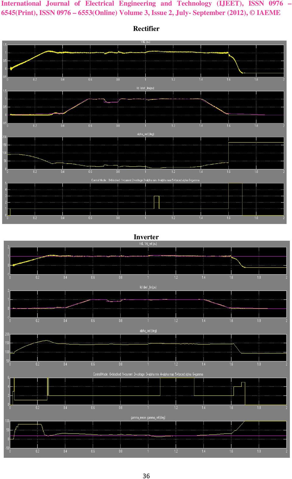
9 In the Master Control, the converters pulse generators are deblocked and the power transmission started by ramping the reference current at t = 20 ms. The reference reaches the minimum value of 0.1 pu in 0.3 s. Observe that the DC current starts to build and the DC line is charged at its nominal voltage. At t = 0.4 s, the reference current is ramped from 0.1 to 1 pu (2 ka) in 0.18 s (5 pu/s). The DC current reaches steady state at the end of the starting sequence at approximately 0.58 s. The rectifier controls the current and the inverter controls the voltage. Trace 1 of both Rectifier and Inverter scopes shows the DC line voltage (1 pu = 500 kv). At the inverter, the voltage reference is also shown. Trace 2 shows the reference current and the measured Id current (1 pu = 2 ka). During the ramp, the inverter is actually controlling the current (Trace 4: Mode = 1) to the value of Id_ref_lim less the Current Margin (0.1 pu) and the rectifier tries to control the current at Id_ref_lim. At the inverter, the control mode changes from current control to gamma control (Mode = 6) before stabilizing to voltage control (Mode = 2) at t = 0.3 s. The rectifier becomes thereafter in control of the current. However, a control mode change will occur and alpha is limited to the minimum value of 5 degrees (Mode = 3) during an increase of the DC voltage initiated by a voltage reference increase at the inverter, as explained in the next paragraph. At steady state (measured at t between 1.3 and 1.4 s), the α firing angles are around 16.5 degrees and 143 degrees respectively on the rectifier and inverter side. At the inverter, two Gamma Measurement blocks measure the extinction angle γ for each thyristor of the two six-pulse bridges (i.e., the bridge connected to the Wye and Delta windings) by determining the elapsed time expressed in electrical degrees from the end of current conduction to the zero crossing of the commutating mutating voltage. The mean value of the measured gamma for the last 12 extinctions (6 of the Delta converter and 6 of the Wye converter) is shown in traces 5 along with Gamma reference. In steady state, the mean γ is around 22.5 degrees. At t = 0.7 s, a -0.2 pu step is applied during 0.1 s to the reference current so that you can observe the dynamic response of the regulators. Later on, at t = 1.0 s, a 0.1 pu step is applied during 0.2 s at the inverter reference voltage. Observe that at the inverter the extinction angle reaches the reference value (e.g., the minimum acceptable value) and that the Gamma regulator takes control at t around 1.1 s. At t around 1.3 s the voltage regulator retakes control of the voltage. At t = 1.4 s the Stop sequence is initiated ted by ramping down the current to 0.1 pu. At t = 1.6 s a Forced-alpha (to 166 deg) at the rectifier extinguishes the current and at the inverter the Forced-alpha (to 92 deg with a limited rate) brings down the DC voltage due to the trapped charge in the line capacitance. At t = 1.7 s the pulses are blocked in both converters. Comparison of Theory and Simulation Results in Steady State The following expression relates the mean direct voltage Vd of a 12-pulse bridge to the direct current Id and firing angle α (neglecting the ohmic losses in the transformer and thyristors): where Vdo is the ideal no-load direct voltage for a six-pulse bridge: Vc is the line-to-line RMS commutating voltage that is dependent on the AC system voltage and the transformer ratio. Rc is the equivalent commutating resistance. Xc is the commutating reactance or transformer reactance referred to the valve side. The following parameters were taken for simulation: Vc = 0.96 * 200 kv/0.90 = kv Id = 2 ka α = 16.5º Xc = 0.24 pu, based on 1200 MVA and kv = Ω 37
. At the inverter, the voltage reference is also shown.")
10 Therefore, this theoretical voltage corresponds well with the expected rectifier voltage calculated from the inverter voltage and the voltage drop in the DC line (R = 4.5 Ω) and in the rectifier smoothing reactor (R = 1 Ω): The µ commutation or overlap angle can also be calculated. Its theoretical value depends on α, the DC current Id, and the commutation reactance Xc. REFERENCE 1. Arrilaga, J., High Voltage Direct Current Transmission, IEEE Power Engineering Series 6, Peter Peregrinus, Ltd., Lidong Zhang, Lars Dofnas, "A Novel Method to Mitigate Commutation Failures in HVDC Systems," Proceedings PowerCon International Conference on, Volume: 1, Oct. 2002, pp Sindark, under Economics, Science and Environment. energy/, HVDC Transmission for Renewable Energy 4. Wikipedia.org, 5. MATLAB/SIMULINK help toolbox documentation, 6. Siemens High Voltage Direct Current Transmission, 38

HVDC 2000 a new generation of high-voltage DC converter stations
 HVDC 2000 a new generation of high-voltage DC converter stations Improved performance and robustness, shorter lead times and faster delivery, plus reduced maintenance needs, were the development goals
Product Data Bulletin
 Product Data Bulletin Power System Harmonics Causes and Effects of Variable Frequency Drives Relative to the IEEE 519-1992 Standard Raleigh, NC, U.S.A. INTRODUCTION This document describes power system
DC TRANSMISSION BASED ON VOLTAGE SOURCE CONVERTERS
 DC TRANSMISSION BASED ON VOLTAGE SOURCE CONVERTERS by Gunnar Asplund, Kjell Eriksson, Hongbo Jiang, Johan Lindberg, Rolf Pålsson, Kjell Svensson ABB Power Systems AB Sweden SUMMARY Voltage Source Converters
High Voltage Direct Current Transmission
 www.siemens.com/energy/hvdc High Voltage Direct Current Transmission Proven Technology for Power Exchange Answers for energy. 2 Contents Chapter Theme Page 1 Why High Voltage Direct Current? 4 2 Main Types
HVDC Light, a tool for electric power transmission to distant loads
 Presented at VI Sepope Conference, Salvador, Brazil, May 1998 HVDC Light, a tool for electric power transmission to distant loads by Gunnar Asplund Kjell Eriksson* Ove Tollerz ABB Power Systems AB ABB
Renewable Energy Grid Integration
 Renewable Energy Grid Integration Jian Sun Professor and Director Grid Integration Issues Cost, Reliability & Efficiency of Grid Interface Grid Congestion, Weak Grids Variability of Renewable Production
COMPARISON OF THE FACTS EQUIPMENT OPERATION IN TRANSMISSION AND DISTRIBUTION SYSTEMS
 COMPARISON OF THE FACTS EQUIPMENT OPERATION IN TRANSMISSION AND DISTRIBUTION SYSTEMS Afshin LASHKAR ARA Azad University of Dezfoul - Iran A_lashkarara@hotmail.com Seyed Ali NABAVI NIAKI University of Mazandaran
Smart Grid and Renewable Energy Grid Integration. Jian Sun, Professor and Director Department of ECSE & Center for Future Energy Systems
 Smart Grid and Renewable Energy Grid Integration Jian Sun, Professor and Director Department of ECSE & Center for Future Energy Systems 1 How Smart Can We Make This Grid? 2 Smart Grid Drivers Need to Use
2012 San Francisco Colloquium
 2012 San Francisco Colloquium http : //www.cigre.org HVDC and Power Electronic Systems for Overhead Line and Insulated Cable Applications B4-8 Trans Bay Cable A Breakthrough of VSC Multilevel Converters
CO-ORDINATION OF PARALLEL AC-DC SYSTEMS FOR OPTIMUM PERFORMANCE
 CO-ORDINATION OF PARALLEL AC-DC SYSTEMS FOR OPTIMUM PERFORMANCE Ana Diez Castro & Rickard Ellström Ying Jiang Häfner Christer Liljegren Vattenfall Utveckling AB ABB Power Systems Gotlands Energiverk AB
Introduction. Harmonics and IEEE 519 Page 1 of 19
 Introduction In an ideal power system, the voltage supplied to customer equipment, and the resulting load current are perfect sine waves. In practice, however, conditions are never ideal, so these waveforms
Low Frequency AC Transmission System
 , pp. 315-326 http://dx.doi.org/10.14257/ijsip.2015.8.5.32 Low Frequency AC Transmission System G. Sirisha Kumari 1 and K.Veerendranath 2 1 M. Tech student in EEE Department 2 Asst. Professor in EEE Department
Voltage Stability Improvement using Static Var Compensator in Power Systems
 Leonardo Journal of Sciences ISSN 1583-0233 Issue 14, January-June 2009 p. 167-172 Voltage Stability Improvement using Static Var Compensator in Power Systems Department of Electrical/Computer Engineering,
Topics. HVDC Fundamentals
 Topics HVDC Fundamentals Conventional Converters Capacitor Commutated Converters Voltage Source Converters Reactive Power Requirements System Configurations Tapping Control basics High Power Transmission
EMTP STUDIES PERFORMED TO INSERT LONG AC CABLES IN THE FRENCH GRID
 Tension (kv) Impedance (Ohms) EMTP STUDIES PERFORMED TO INSERT LONG AC CABLES IN THE FRENCH GRID frequency (Hz) Simon DESCHANVRES Yannick VERNAY RTE, CNER, Substations Department t (ms) EMTP-RV Users Group
HVDC Transmission. Dennis A. Woodford. Manitoba HVDC Research Centre. 400-1619 Pembina Highway. Winnipeg, Manitoba, R3T 3Y6. Canada.
 HVDC Transmission by Dennis A. Woodford Manitoba HVDC Research Centre 400-1619 Pembina Highway Winnipeg, Manitoba, R3T 3Y6 Canada 18 March 1998 INTRODUCTION Electric power transmission was originally developed
HVDC Technology for Large Scale Offshore Wind Connections
 HVDC Technology for Large Scale Offshore Wind Connections Nandan Mahimkar, Gunnar Persson,Claes Westerlind, ABB AB, SE-771 80, Ludvika, Sweden, nandan.mahimkar@in.abb.com, gunnar.persson@se.abb.com,claes.westerlind@se.abb.com,
MINISTERIE VAN ECONOMISCHE ZAKEN GENERAL COST COMPARISON BETWEEN UNDERGROUND CABLES AND O.H. LINE SYSTEMS FOR H.V. TRANSMISSION
 MINISTERIE VAN ECONOMISCHE ZAKEN GENERAL COST COMPARISON BETWEEN UNDERGROUND CABLES AND O.H. LINE SYSTEMS FOR H.V. TRANSMISSION REPORT ON NETWORK RELIABILITY ASPECTS OF THE CHOICE LINE VERSUS CABLE FOR
POWER TRANSMISSION FROM OFFSHORE WIND FARMS
 POWER TRNSMISSION FROM OFFSHORE WIND FRMS Thorsten Völker University of pplied Sciences Bremerhaven Germany BSTRCT The future for wind power generation in Germany is offshore wind energy. The preferred
DIMENSIONING OF CURRENT TRANSFORMERS FOR PROTECTON APPLICATION
 ÿþ üûúùø öõöôùóùõò CT Dimensioning DIMENSIONING OF CURRENT TRANSFORMERS FOR PROTECTON APPLICATION Application note GER3973 1 CT Dimensioning ÿþ üûúùø öõöôùóùõò GER-3973 Application note ÿþ üûúùø öõöôùóùõò
Power Transmission and Distribution. High Voltage Direct Current Transmission Proven Technology for Power Exchange
 Power Transmission and Distribution High Voltage Direct Current Transmission Proven Technology for Power Exchange 2 Contents Chapter Theme Page Contents 3 1 Why High Voltage Direct Current? 4 2 Main Types
General Validation Test Program for Wind Power Plants Connected to the Hydro-Québec Transmission System
 General Validation Test Program for Wind Power Plants Connected to the Hydro-Québec Transmission System Direction Planification des actifs et expertise de transport February 2011 TABLE OF CONTENTS 1. CONDUCTING
System Protection Schemes in Eastern Denmark
 System Protection Schemes in Eastern Denmark Joana Rasmussen COWI A/S, Energy Department System Protection Schemes in Eastern Denmark 1.Advanced system protection schemes are investigated and perspectives
Transmissão em Corrente Contínua
 Transmissão em Corrente Contínua Panorama Atual e Perspectivas Futuras no Brasil Multi-Terminal HVDC Classic Some Considerations Brazilian SC B4 Paulo Fischer de Toledo, ABB Basic considerations Traditional
The design and performance of Static Var Compensators for particle accelerators
 CERN-ACC-2015-0104 Karsten.Kahle@cern.ch The design and performance of Static Var Compensators for particle accelerators Karsten Kahle, Francisco R. Blánquez, Charles-Mathieu Genton CERN, Geneva, Switzerland,
Brochure Introducing HVDC
 Brochure Introducing HVDC ABB and HVDC The world s first commercial high-voltage direct current (HVDC) link, situated between the Swedish mainland and the island Gotland, was delivered by ABB already in
SOLAR WIND INTEGRATED SYSTEM ON OFFSHORE WITH LOW FREQUENCY POWER TRANSMISSION
 SOLAR WIND INTEGRATED SYSTEM ON OFFSHORE WITH LOW FREQUENCY POWER TRANSMISSION Baggu Rajesh Kumar 1, D.Revathi 2 PG Student, Department of EEE, KIET, Kakinada, India. 1 Asst.Professor, Department of EEE,
USE OF ARNO CONVERTER AND MOTOR-GENERATOR SET TO CONVERT A SINGLE-PHASE AC SUPPLY TO A THREE-PHASE AC FOR CONTROLLING THE SPEED OF A THREE-PHASE INDUCTION MOTOR BY USING A THREE-PHASE TO THREE-PHASE CYCLOCONVERTER
 International Journal of Electrical Engineering & Technology (IJEET) Volume 7, Issue 2, March-April, 2016, pp.19-28, Article ID: IJEET_07_02_003 Available online at http:// http://www.iaeme.com/ijeet/issues.asp?jtype=ijeet&vtype=7&itype=2
Transient analysis of integrated solar/diesel hybrid power system using MATLAB Simulink
 Transient analysis of integrated solar/diesel hybrid power system using ATLAB Simulink Takyin Taky Chan School of Electrical Engineering Victoria University PO Box 14428 C, elbourne 81, Australia. Taky.Chan@vu.edu.au
WIND TURBINE TECHNOLOGY
 Module 2.2-2 WIND TURBINE TECHNOLOGY Electrical System Gerhard J. Gerdes Workshop on Renewable Energies November 14-25, 2005 Nadi, Republic of the Fiji Islands Contents Module 2.2 Types of generator systems
HVDC-VSC: transmission technology of the future
 A bi-pole ± 285 kv HVDC line sandwiched between 3-phase 400 kv HVAC lines. HVDC-VSC: transmission technology of the future A new hybrid HVDC circuit technology using voltage source converters is only half
High Voltage Direct Current Transmission. Proven Technology for Power Exchange. Answers for energy.
 High Voltage Direct Current Transmission Proven Technology for Power Exchange Answers for energy. 1 2 Contents Chapter Theme Page 1 Why High Voltage Direct Current? 4 2 Main Types of HVDC Schemes 6 3 Converter
Three Gorges - Changzhou HVDC : Ready to Bring Bulk Power to East
 The 4 th International Conference on Power Transmission & Distribution Technology 2003 14-16 October, 2003, Changsha 2003 Three Gorges - Changzhou HVDC : Ready to Bring Bulk Power to East Abhay Kumar Mats
Transformerless UPS systems and the 9900 By: John Steele, EIT Engineering Manager
 Transformerless UPS systems and the 9900 By: John Steele, EIT Engineering Manager Introduction There is a growing trend in the UPS industry to create a highly efficient, more lightweight and smaller UPS
FACTS. Solutions to optimise network performance GRID
 Solutions to optimise network performance GRID Solutions to optimise your network Our worldwide presence: Better solutions for your network all around the world Tampere Philadelphia Stafford Konstanz Beijing
Power Technology Issue 106. Modeling of Three-Winding Voltage Regulating Transformers for Positive Sequence Load Flow Analysis in PSS E
 SIEMENS Siemens Energy, Inc. Power Technology Issue 106 Modeling of Three-Winding Voltage Regulating Transformers for Positive Sequence Load Flow Analysis in PSS E Carlos Grande-Moran, Ph.D. Principal
POWER SYSTEM HARMONICS. A Reference Guide to Causes, Effects and Corrective Measures AN ALLEN-BRADLEY SERIES OF ISSUES AND ANSWERS
 A Reference Guide to Causes, Effects and Corrective Measures AN ALLEN-BRADLEY SERIES OF ISSUES AND ANSWERS By: Robert G. Ellis, P. Eng., Rockwell Automation Medium Voltage Business CONTENTS INTRODUCTION...
Submarine Cable Power Transmission using DC High-Voltage Three-Level Converters
 Submarine Cable Power Transmission using DC High-Voltage Three-Level Converters João Antunes, IST (jlantunes@gmail.com) Astract This paper is about multilevel converters used in High Voltage Direct Current
Diode Applications. by Kenneth A. Kuhn Sept. 1, 2008. This note illustrates some common applications of diodes.
 by Kenneth A. Kuhn Sept. 1, 2008 This note illustrates some common applications of diodes. Power supply applications A common application for diodes is converting AC to DC. Although half-wave rectification
Power Technology Issue 104. Modeling of Two-Winding Voltage Regulating Transformers for Positive Sequence Load Flow Analysis in PSS E
 SIEMENS Siemens Energy, Inc. Power Technology Issue 104 Modeling of TwoWinding Voltage Regulating Transformers for Positive Sequence Load Flow Analysis in PSS E Carlos GrandeMoran, Ph.D. Principal Consultant
Assessment of the Technical Issues relating to Significant Amounts of EHV Underground Cable in the All-island Electricity Transmission System
 Assessment of the Technical Issues relating to Significant Amounts of EHV Underground Cable in the All-island Electricity Transmission System Summary Report November 2009 Technical Report on using EHV
Variable Frequency Drives - a Comparison of VSI versus LCI Systems
 Variable Frequency Drives - a Comparison of VSI versus LCI Systems Introduction TMEIC is a leader in the innovative design and manufacture of large ac variable f requency drive systems. TMEIC has been
Control Development and Modeling for Flexible DC Grids in Modelica
 Control Development and Modeling for Flexible DC Grids in Modelica Andreas Olenmark 1 Jens Sloth 2 Anna Johnsson 3 Carl Wilhelmsson 3 Jörgen Svensson 4 1 One Nordic AB, Sweden, andreas.olenmark@one-nordic.se.
300 MW Variable Speed Drives for Pump-Storage Plant Application Goldisthal
 May 24 MW Variable Speed Drives for Aurélie Bocquel APCG / 4BOC4 (MW-Goldisthal 1-5-24).PPT MW Variable Speed Drives for Content Major benefits of the cyclo-converter driven doubly-fed induction machines
Reactive Power Control of an Alternator with Static Excitation System Connected to a Network
 Reactive Power Control of an Alternator with Static Excitation System Connected to a Network Dr. Dhiya Ali Al-Nimma Assist. Prof. Mosul Unoversity Dr. Majid Salim Matti lecturer Mosul University Abstract
Electrical Considerations for HVDC Transmission Lines. Joe Mooney, PE
 Electrical Considerations for HVDC Transmission Lines Joe Mooney, PE POWER Engineers has met the standards and requirements of the Registered Continuing Education Program. Credit earned on completion of
Introduction to The Trans Bay Cable Project
 Introduction to The Trans Bay Cable Project We ve come a long way 1 But thanks to the advances of two men and 2 The Battle of Currents 3 Utilities are able to choose the most effective and efficient means
Offshore Platform Powered With New Electrical Motor Drive System
 Offshore Platform Powered With New Electrical Motor Drive System Authors: Jan O. Lamell, M.Sc E.E. ABB Automation Technologies Presenters: Thomas Johansson, M.Sc E.E. ABB Automation Technologies Timothy
B4-207. Konti-Skan 1 HVDC Pole Replacement
 21, rue d'artois, F-75008 Paris http://www.cigre.org B4-207 Session 2004 CIGRÉ Konti-Skan 1 HVDC Pole Replacement P L Sorensen 1, B Franzén 2, J D Wheeler 3, R E Bonchang 3, C D Barker 3, R M Preedy 3,
How To Understand And Understand The Theory Of Electricity
 DIRECT CURRENT AND ALTERNATING CURRENT SYSTEMS N. Rajkumar, Research Fellow, Energy Systems Group, City University Northampton Square, London EC1V 0HB, UK Keywords: Electrical energy, direct current, alternating
Chapter 3 AUTOMATIC VOLTAGE CONTROL
 Chapter 3 AUTOMATIC VOLTAGE CONTROL . INTRODUCTION TO EXCITATION SYSTEM The basic function of an excitation system is to provide necessary direct current to the field winding of the synchronous generator.
HARMONIC DISTORTION IN THE ELECTRIC SUPPLY SYSTEM
 Technical Note No.3 March 2000 HARMONIC DISTORTION IN THE ELECTRIC SUPPLY SYSTEM This Technical Note discusses harmonic distortion, its causes and adverse effects, what levels are unacceptable and how
100% Stator Ground Fault Detection Implementation at Hibbard Renewable Energy Center. 598 N. Buth Rd 3215 Arrowhead Rd
 100% Stator Ground Fault Detection Implementation at Hibbard Renewable Energy Center Introduction Roger Hedding Steven Schoenherr, P.E. ABB Inc. Minnesota Power 598 N. Buth Rd 3215 Arrowhead Rd Dousman,
Power System review W I L L I A M V. T O R R E A P R I L 1 0, 2 0 1 3
 Power System review W I L L I A M V. T O R R E A P R I L 1 0, 2 0 1 3 Basics of Power systems Network topology Transmission and Distribution Load and Resource Balance Economic Dispatch Steady State System
Reactive Power and Importance to Bulk Power System OAK RIDGE NATIONAL LABORATORY ENGINEERING SCIENCE & TECHNOLOGY DIVISION
 Reactive Power and Importance to Bulk Power System OAK RIDGE NATIONAL LABORATORY ENGINEERING SCIENCE & TECHNOLOGY DIVISION Outline What is Reactive Power and where does it come from? Why is it important?
HVDC. A firewall against disturbances in high-voltage grids. Lennart Carlsson
 A firewall against disturbances in high-voltage grids Lennart Carlsson Interconnections between grids are desirable because they not only permit economies through the sharing of reserves, but they also
Bill is the author of 15 papers and lectures on transmission lines and other power system topics.
 Transmission Lines Electricity s Highway This talk starts with an explanation of Surge Impedance Loading and demonstrates how it is used for transmission line work. The St. Clair Curve widely used in transmission
Power Electronics. Prof. K. Gopakumar. Centre for Electronics Design and Technology. Indian Institute of Science, Bangalore.
 Power Electronics Prof. K. Gopakumar Centre for Electronics Design and Technology Indian Institute of Science, Bangalore Lecture - 1 Electric Drive Today, we will start with the topic on industrial drive
Modeling of Transmission Lines
 Modeling of Transmission Lines Electric Power Transmission The electric energy produced at generating stations is transported over high-voltage transmission lines to utilization points. The trend toward
Properties of electrical signals
 DC Voltage Component (Average voltage) Properties of electrical signals v(t) = V DC + v ac (t) V DC is the voltage value displayed on a DC voltmeter Triangular waveform DC component Half-wave rectifier
EMI in Electric Vehicles
 EMI in Electric Vehicles S. Guttowski, S. Weber, E. Hoene, W. John, H. Reichl Fraunhofer Institute for Reliability and Microintegration Gustav-Meyer-Allee 25, 13355 Berlin, Germany Phone: ++49(0)3046403144,
Grid Interconnection of Renewable Energy Sources Using Modified One-Cycle Control Technique
 Grid Interconnection of Renewable Energy Sources Using Modified One-Cycle Control Technique NKV.Sai Sunil 1, K.Vinod Kumar 2 PG Student, GITAM University, Visakhapatnam, India. Asst.Professor, Department
factsheet High Voltage Direct Current electricity technical information
 factsheet High Voltage Direct Current electricity technical information Introduction High voltage direct current (HVDC) technology is one of the technical options National Grid can consider for the future
Knowing the FACTS. FACTS that enhance power quality in rail feeder systems
 Knowing the FACTS FACTS that enhance power quality in rail feeder systems ROLF GRÜNBAUM, PER HALVARSSON, BJÖRN THORVALDSSON The increase in traffic on existing tracks combined with new high-speed rail
Summary of Electric Transmission Assessment Report
 Summary of Electric Transmission Assessment Report January 2010 Assessment and Analysis of the State-Of-the-Art High-Voltage Electric Transmission Systems with Specific Focus on High-Voltage Direct Current
Relationship between large subject matter areas
 H02M APPARATUS FOR CONVERSION BETWEEN AC AND AC, BETWEEN AC AND DC, OR BETWEEN DC AND DC, AND FOR USE WITH MAINS OR SIMILAR POWER SUPPLY SYSTEMS; CONVERSION OF DC OR AC INPUT POWER INTO SURGE OUTPUT POWER;
Harmonics and Noise in Photovoltaic (PV) Inverter and the Mitigation Strategies
 Inverter and the Mitigation Strategies") Soonwook Hong, Ph. D. Michael Zuercher Martinson Harmonics and Noise in Photovoltaic (PV) Inverter and the Mitigation Strategies 1. Introduction PV inverters use semiconductor devices to transform the
Soonwook Hong, Ph. D. Michael Zuercher Martinson Harmonics and Noise in Photovoltaic (PV) Inverter and the Mitigation Strategies 1. Introduction PV inverters use semiconductor devices to transform the
Chapter 24. Three-Phase Voltage Generation
 Chapter 24 Three-Phase Systems Three-Phase Voltage Generation Three-phase generators Three sets of windings and produce three ac voltages Windings are placed 120 apart Voltages are three identical sinusoidal
www.siemens.com/energy/uhvdc The Bulk Way UHV DC the new dimension of efficiency in HVDC transmission Answers for energy.
 www.siemens.com/energy/uhvdc The Bulk Way UHV DC the new dimension of efficiency in HVDC transmission Answers for energy. Shape up for the future of power transmission Siemens UHV DC helps meet the steadily
Technical Information Requirement for MV transformers and transformer for internal power supplies for SUNNY CENTRAL
 Technical Information Requirement for MV transformers and transformer for internal power supplies for SUNNY CENTRAL SC_Trafo-TI-en-62 Version 6.2 ENGLISH Table of Contents SMA Solar Technology Table of
Grounding of Electrical Systems NEW CODE: Grounding and Bonding
 Grounding of Electrical Systems NEW CODE: Grounding and Bonding Presented By Scott Peele PE Grounding of Electrical Systems Outline Defining the Terms Why should I Ground? Types of Grounding Systems Separately
Line Reactors and AC Drives
 Line Reactors and AC Drives Rockwell Automation Mequon Wisconsin Quite often, line and load reactors are installed on AC drives without a solid understanding of why or what the positive and negative consequences
The following table shows approximate percentage wise the
 SHORT-CIRCUIT CALCULATION INTRODUCTION Designing an electrical system is easy and simple, if only the normal operation of the network is taken into consideration. However, abnormal conditions which are
Impedance Matching and Matching Networks. Valentin Todorow, December, 2009
 Impedance Matching and Matching Networks Valentin Todorow, December, 2009 RF for Plasma Processing - Definition of RF What is RF? The IEEE Standard Dictionary of Electrical and Electronics Terms defines
Inrush Current. Although the concepts stated are universal, this application note was written specifically for Interpoint products.
 INTERPOINT Although the concepts stated are universal, this application note was written specifically for Interpoint products. In today s applications, high surge currents coming from the dc bus are a
Critical thin-film processes such as deposition and etching take place in a vacuum
 WHITEPAPER INTRODUCING POWER SUPPLIES AND PLASMA Critical thin-film processes such as deposition and etching take place in a vacuum SYSTEMS chamber in the presence of a plasma. A plasma is an electrically
Fundamentals of Power Electronics. Robert W. Erickson University of Colorado, Boulder
 Robert W. Erickson University of Colorado, Boulder 1 1.1. Introduction to power processing 1.2. Some applications of power electronics 1.3. Elements of power electronics Summary of the course 2 1.1 Introduction
The Facts About Harmonics and Power Factor. Power Quality: Harmonics & Power Factor Correction
 The Facts About Harmonics and Power Factor Power Quality: Harmonics & Power Factor Correction 1 Agenda I. Harmonic Basics II. Harmonic Mitigation Methods III. Active Harmonic Filters IV. Applications V.
2. A conductor of length 2m moves at 4m/s at 30 to a uniform magnetic field of 0.1T. Which one of the following gives the e.m.f. generated?
 Extra Questions - 2 1. A straight length of wire moves through a uniform magnetic field. The e.m.f. produced across the ends of the wire will be maximum if it moves: a) along the lines of magnetic flux
Solar Power Plant Design and Interconnection
 Solar Power Plant Design and Interconnection Wind & Solar Super Session July 27, 2011 E.H. Camm, S.E. Williams S&C Electric Company Outline Introduction Utility-scale PV power plant Grounding Reactive
(3 )Three Phase Alternating Voltage and Current
Three Phase Alternating Voltage and Current") EEE 2015 EECTRCS (3) Monophase 1 Three phase Three phase electric power is a common method of alternating current electric power generation, transmission, and distribution. t is a type of polyphase system
EEE 2015 EECTRCS (3) Monophase 1 Three phase Three phase electric power is a common method of alternating current electric power generation, transmission, and distribution. t is a type of polyphase system
GenTech Practice Questions
 GenTech Practice Questions Basic Electronics Test: This test will assess your knowledge of and ability to apply the principles of Basic Electronics. This test is comprised of 90 questions in the following
The Importance of the X/R Ratio in Low-Voltage Short Circuit Studies
 The Importance of the X/R Ratio in Low-Voltage Short Circuit Studies DATE: November 17, 1999 REVISION: AUTHOR: John Merrell Introduction In some short circuit studies, the X/R ratio is ignored when comparing
SIMULATING HYBRID ENERGY GRIDS IN SMART CITIES FOCUS ON ELECTRIC ENERGY SYSTEMS
 Sawsan Henein AIT Austrian Institute of Technology Electric Energy Systems Research Group SIMULATING HYBRID ENERGY GRIDS IN SMART CITIES FOCUS ON ELECTRIC ENERGY SYSTEMS Sustainable Places 2015 Savona,
Electric Power Systems An Overview. Y. Baghzouz Professor of Electrical Engineering University of Nevada, Las Vegas
 Electric Power Systems An Overview Y. Baghzouz Professor of Electrical Engineering University of Nevada, Las Vegas Overview Power Generation Conventional power generation Power generation from renewables
The stable way. Synchronous condenser solutions. siemens.com/energy/facts
 The stable way Synchronous condenser solutions siemens.com/energy/facts Bringing grids in line with new requirements Global climate change poses new challenges for power generation and transmission. Innovative
Limiting Grid Disturbances of Renewable Power Sources b.m.o Modern Power Electronics Paper ID FT3-5.2; 25.10.2006, 16h30-17h00
 Limiting Grid Disturbances of Renewable Power Sources b.m.o Modern Power Electronics Paper ID FT3-5.2; 25.10.2006, 16h30-17h00 Reinhard Zingel, Converteam GmbH, Culemeyerstr.1, 12277 Berlin ETG2006 ID
Chapter 9 Balanced Faults
 Chapter 9 alanced Faults 9.1 Introduction The most common types of fault are (in order) single-line-to-ground fault, line-to-line fault, and double-line-to-ground fault. All of these are unbalanced faults.
Project description. Power Electronics for Reliable and Energy efficient Renewable Energy Systems
 Project description Title: Power Electronics for Reliable and Energy efficient Renewable Energy Systems OBJECTIVES Principal objective Provide competence and decision basis for enabling reliable and energy
LAB1 INTRODUCTION TO PSS/E EE 461 Power Systems Colorado State University
 LAB1 INTRODUCTION TO PSS/E EE 461 Power Systems Colorado State University PURPOSE: The purpose of this lab is to introduce PSS/E. This lab will introduce the following aspects of PSS/E: Introduction to
EEL303: Power Engineering I - Tutorial 4
 1. Determine the voltage at the generating station and the efficiency of the following system (Figure 1): Both transformers have ratio of 2kV/11kV. The resistance on LV side of both Figure 1: transformers
Improvements of Reliability of Micro Hydro Power Plants in Sri Lanka
 Improvements of Reliability of Micro Hydro Power Plants in Sri Lanka S S B Udugampala, V Vijayarajah, N T L W Vithanawasam, W M S C Weerasinghe, Supervised by: Eng J Karunanayake, Dr. K T M U Hemapala
Wide Area Monitoring Current Continental Europe TSOs Applications Overview
 Wide Area Monitoring Current Continental Europe TSOs Applications Overview Version 5 System Protection & Dynamics Working Group 20th September 2015 1. Content 1. Content... 2 2. Introduction... 3 3. Main
A COMPARISON ON PERFORMANCE OF TCSC/SSSC FOR A RADIAL SYSTEM
 IMPACT: International Journal of Research in Engineering & Technology (IMPACT: IJRET) ISSN(E): 31-8843; ISSN(P): 347-4599 Vol. 3, Issue 9, Sep 015, 7-18 Impact Journals A COMPARISON ON PERFORMANCE OF TCSC/SSSC
Power System Harmonics
 Pacific Gas and Electric Company Power System Harmonics What are power system harmonics? Ideally, voltage and current waveforms are perfect sinusoids. However, because of the increased popularity of electronic
2012 San Francisco Colloquium
 2012 San Francisco Colloquium http : //www.cigre.org Advances in voltage source converter (VSC) technologies B4-6 500 kv VSC Transmission System for lines and cables B. JACOBSON, B. WESTMAN, M. P. BAHRMAN*
Request for Payment Instructions Wholesale Distribution Access Tariff (WDAT) Attachment I - GIP
 Attachment I - GIP") Grid Interconnection & Contract Development Request for Payment Instructions Wholesale Distribution Access Tariff (WDAT) Attachment I - GIP Submittal Instructions Prior to submitting your application and
Grid Interconnection & Contract Development Request for Payment Instructions Wholesale Distribution Access Tariff (WDAT) Attachment I - GIP Submittal Instructions Prior to submitting your application and
CYCLOCONVERTERS. Fig.1 Block diagram of a cycloconverter
 CYCLOCONVERTERS Burak Ozpineci, Leon M. Tolbert Department of Electrical and Computer Engineering University of Tennessee-Knoxville Knoxville, TN 37996-2100 In industrial applications, two forms of electrical
Application Guide. Power Factor Correction (PFC) Basics
 Basics") Power Factor Correction (PFC) Basics Introduction Power Factor, in simple terms, is a number between zero and one that represents the ratio of the real power to apparent power. Real power (P), measured
Power Factor Correction (PFC) Basics Introduction Power Factor, in simple terms, is a number between zero and one that represents the ratio of the real power to apparent power. Real power (P), measured
Distributed Flexible AC Transmission System (D FACTS) Jamie Weber. weber@powerworld.com, 217 384 6330 ext. 13
 Jamie Weber. weber@powerworld.com, 217 384 6330 ext. 13") Distributed Flexible AC Transmission System (D FACTS) Jamie Weber weber@powerworld.com, 217 384 6330 ext. 13 Slide Preparation: Kate Rogers Davis kate@powerworld.com, 217 384 6330, Ext 14 2001 South First
Distributed Flexible AC Transmission System (D FACTS) Jamie Weber weber@powerworld.com, 217 384 6330 ext. 13 Slide Preparation: Kate Rogers Davis kate@powerworld.com, 217 384 6330, Ext 14 2001 South First