Transformerless UPS systems and the 9900 By: John Steele, EIT Engineering Manager
|
|
|
- Ambrose Marshall
- 9 years ago
- Views:
Transcription
1 Transformerless UPS systems and the 9900 By: John Steele, EIT Engineering Manager Introduction There is a growing trend in the UPS industry to create a highly efficient, more lightweight and smaller UPS system. Data Centers across the world are constantly searching for new ways to maximize reliable UPS power while minimizing the UPS and associated equipment footprint. In addition, operating costs for large data centers always will be a priority. In applications which require a smaller capacity UPS (less than 200 kw), true on-line double conversion transformerless UPS systems have emerged as the topology of choice. In larger applications, most UPS systems consist of a UPS with a transformer, or multiple smaller UPS power modules paralleled together to achieve the required capacity. Most UPS manufacturers are finding it difficult to create a true on-line double conversion transformerless UPS system larger than 200 kw due to factors such as ground faults, high frequency noise and efficiency. Transformerless UPS systems utilize Insulated Gate Bipolar Transistor (IGBT) for all power conversion processes (AC/DC converter, DC/DC chopper and the DC/AC inverter). IGBTs are much faster than the traditional thyristor and can be controlled by simply toggling an on/off gate signal using a digital signal processor and a field programmable gate array as opposed to waiting for a zero crossing. When the gate signal is removed, the IGBT turns off. The combination creates a series of pulses to re-shape existing voltages (conversion from AC to DC and from DC back to AC). As with any switching power electronic, the device itself has power losses. For the IGBT, the two primary losses are the conduction losses and the switching losses. Since the IGBTs are being turned on and turned off much faster, the switching losses will increase creating a less efficient system. This is a challenge most manufacturers have been unable to overcome in larger capacity UPS systems. For this reason, many UPS manufacturers will still use thyristors as opposed to IGBTs in the converter section of the UPS (rectifier section). Although there are many benefits in using IGBTs in the converter section, a decrease in efficiency prevents this from being a preferred option for most in larger UPS kw rated systems (above 200 kw). In the UPS inverter, the benefits of the IGBT switching speed have far outweighed the decrease in efficiency. It is important to note that a transformer serves many purposes in the UPS system. Even if the UPS utilizes IGBTs for switching, a transformer would still have a purpose. Other technologies such as the IGBT switching controls and fault detection still need to be considered. This paper will discuss the new technologies used in transformerless UPS systems and the advances in the Mitsubishi 9900 series UPS systems.
, true on-line double conversion transformerless UPS systems have emerged as the topology of choice.")
2 Background Before the advances in UPS controls and the benefits of the IGBT in the converter and inverter can start to be appreciated, the primary and secondary purposes of the transformer in traditional UPS systems must first be discussed. Converter Section: The main purpose of the converter section of the UPS is to convert the AC utility power to DC power. The most popular power electronics used for this process are the Diode (6 pulse), the thyristor (SCR 6 pulse and SCR 12 pulse) and the IGBT. Until recently, the 6 pulse and the 12 pulse SCR rectifier have been the most popular. As shown in figure 2, the 12 pulse SCR rectifier uses an isolation transformer in combination with two 6 pulse SCR rectifiers (figure 1 shows a 6 pulse SCR rectifier). The 30 Degree phase shift provided by the transformer is the main purpose of the isolation transformer. The two 6 pulse SCR rectifiers will alternate to create twice as many pulses. The 12 pulse SCR rectifier will produce fewer harmonics than the single 6 pulse SCR rectifier allowing for a smaller harmonic filter. Figure 1: 6 pulse rectifier with optional transformer

3 Figure 2: 12 pulse rectifier with optional transformer The Diode bridge converter (figure 3) is similar to the 6 pulse SCR rectifier, except the Diodes are natural commutation (natural on and natural off). The benefits of the Diode bridge are better efficiencies and lower harmonics compared to a traditional SCR rectifier. Figure 3: Diode Bridge rectifier with optional transformer

4 Figure 4: IGBT Converter with optional transformer Every rectifier, regardless of the technology or power electronics used, will produce harmonics. For all technologies but the IGBT (figure 4), these harmonics are greater than desired for most electrical systems, including the backup generator. Therefore, an input filter is required to reduce the harmonics to less than 10% i THD. As shown in Figure 5, the input filter is comprised of an inductor with a parallel capacitor. The transformer, in this case, helps add inductance to the line to further reduce the harmonics. Figure 6 shows reflected harmonic distortion on input current waveforms from their respective rectifier or converter technology. Figure 5: Filters for the rectifier section (Left) and inverter section (Right)

5 Figure 6: Input current harmonic comparison Finally, the isolation transformer used in the converter section of the UPS system will provide isolation between the UPS module and the utility. This isolation helps protect against DC ground faults caused by the batteries and will minimize damage to the upstream distribution system due to a separation in the transformer input and output windings. Although some manufacturers have started using IGBTs in the converter section, most are still switching the IGBTs based on the traditional SCR logic. The benefit of using a slower switching speed for the IGBT converter is a higher efficiency (less switching means less switching losses). In this case, the IGBT converter will still produce larger amounts of harmonics, which will require the input harmonic filter (similar to the harmonic filter for the SCR rectifiers). The problem with traditional harmonic filters on the UPS converter is the leading power factor at small loads. When the UPS system is operating at a reduced load, the ratio of capacitance in the input filter to the load becomes very large and will produce a leading power factor from the UPS. This leading power factor can result in generator compatibility issues. To eliminate these issues, an active input filter (switching harmonic filter capacitors in and out of the circuit depending on the load) will need to be used or the input filter would need to be disconnected both resulting in an increased harmonic content.
.")
6 Digitally controlled IGBT converters: IGBT converters offer many benefits over SCR type rectifiers if applied correctly (see figure 4 above). The IGBT converter can switch at speeds in the kilo-hertz range as opposed to the slower SCR rectifier, which fires pulses in the hundreds-hertz range. The reason the SCR rectifiers can not be switched faster is because the thyristors are turned on by a gate signal, but turned off by natural commutation (zero crossing of the AC input sine wave) or by a snubber circuit. If used properly with a digital signal processor and a Field Programmable Gate Array, the IGBT switching can be controlled to minimize the harmonics normally produced by a converter, thus eliminating the input harmonic filter. As stated above, the problem exists with the UPS efficiency. If the IGBT converter is turning on and off in the kilo-hertz range, and the IGBT inverter is turning on and off in the kilo-hertz range, the switching losses will quickly add up creating a less efficient UPS. Inverter Section: Most manufacturers have recognized the importance of using IGBTs in the UPS inverter. The faster switching capabilities of the IGBT, if controlled properly, will result in a less distorted sine wave and will offer better response to various steps in the output loads and improved compatibility with downstream static transfer switches. The IGBTs are fired in a series of pulses, which are used to invert the DC from the converter (or batteries) into a clean sine wave (refer to figure 7). Since the pulses are not continuous, high frequency noise is generated from the inverter. The high frequency noise and harmonic content on the output side of the UPS is filtered using an output filter and an output isolation transformer. Figure 7: IGBT Switching 2-level (top) and 3-level (Bottom) In addition, the isolation transformer on the output of the UPS provides a means to re-establish a neutral ground bond for the downstream distribution.

7 The Mitsubishi 9900 series transformerless UPS systems As mentioned earlier, there are many different factors that need to be considered when designing a transformerless UPS system. Ideally, the UPS should be designed with minimal losses throughout the conversion processes (high efficient UPS). This was one of the design goals for the 9900 series UPS. After researching the available power conversion technologies, it was concluded that the three-level topology offered the most benefits while improving the reliability of the system. The three-level topology reduces the switching losses associated with IGBTs. The result is a more efficient True On-Line Double Conversion UPS system that maintains this higher level of efficiency at loads as low as 10% on the UPS system (reference The Power of Green: Mitsubishi 9900A Series High Efficiency True On-Line Double Conversion Uninterruptible Power Supply (UPS) ). Adding to the efficiency improvements of the 9900 series is the reduction of the filtering requirements. The input current harmonics of the 9900 is controlled to less than 3% at 100% load without the use of an input harmonic filter. Only a small EMI filter is required for the input of the UPS. By eliminating the input harmonic filter, generator compatibility issues due to harmonics and leading power factor are eliminated. On the output, since the Three-Level Topology generates pulses that more closely resemble a sine-wave (see figure 7), the output filter is also minimized. The combination creates a highly reliable and efficient True On-Line Double Conversion UPS system. Reducing the size of the UPS filters and eliminating the transformer will also reduce the size and weight of the UPS system and increase the efficiency. To further enhance the improvements in technology, the 9900 series UPS systems are designed with the newest, most advanced generation of Mitsubishi designed IGBTs. Most manufacturers are still using the second and third generation insulated gate bipolar transistors. Mitsubishi UPS systems are using fourth and fifth generation IGBTs which offer better efficiencies, improved reliability and a lower gate voltage. Although these are all great benefits for the customer, the UPS control techniques and the UPS response to different types of faults that can occur must now be considered. Control System Switching the IGBTs faster is of great benefit, but more important are the control techniques used for the gate signal. The Mitsubishi 9900 series UPS utilizes a high speed Digital Signal Processor (DSP), Application Specific Integrated Circuit (ASIC) and Field Programmable Gate Array (FPGA) for control. As shown in the block diagram of the control circuit, Figure 8, the 9900 series UPS uses a minor current control loop with a major voltage control loop to provide a precise response to various conditions imposed on the UPS.

8 Figure 8: Block diagram of the Mitsubishi Control circuit for a UPS Data from the voltage major control loop is collected and evaluated in the digital signal processor (DSP). The field programmable gate array (FPGA) is used to collect information provided by the DSP in addition to comparing the currents from the current minor control loops. Application specific programming in the FPGA processes the information and provides a switching sequence to compensate for the specific scenarios the load presents. The multiple feedback control loop allows the UPS logic to quickly detect changes in current in addition to detecting deviations to the voltage allowing for more precise control of the IGBT switching. By using the DSP and the FPGA, which have samplings rate greater than 48 khz (800 times per cycle), the switching sequence of the IGBTs can be manipulated to provide complete control of the power conversion processes. In the event a fault occurs (including short circuits) which produces currents exceeding the current limits of the UPS (input or output), the control circuit will immediately stop firing the IGBTs and initiate the opening and closing of the contactors. On the converter section, the input contactor will open and the UPS will operate from the battery source. On the inverter, the UPS will initiate a transfer to bypass to allow the bypass current protection to clear the fault.

9 With minimal voltage distortion, the UPS will support any currents that do not exceed the limits of the system, including downstream inrush currents. For example, the UPS inverter can support 0% to 100% step loads on the UPS output while maintaining a voltage with less than 2% deviation (See Figure 9). Since the converter section is also controlled using the same logic, the converter can support the same step loads to the input of the inverter. Therefore, the UPS does not require power from the battery system to perform this step load. Figure 9: 100% step load on a 9900 series UPS without batteries Control in Multi-Module applications: The 9900 series UPS is capable of multiple module configurations (MMS), up to eight kva matched units in parallel. For all multi-module 9900 series UPS systems, single modules are used without any changes. The same logic is used in each UPS in the multi-module configuration. For a multi-module system, redundant Cat 5e cables are used to connect the DSP and the FPGA of each UPS together. Therefore, the control logic will be looking at its own minor and major control loops, and also the information from the other UPS control loops, to match the output of each UPS on the critical bus. The result is a multi-module system which can instantaneously share load while maintaining clean, reliable, regulated and uninterrupted voltage on the critical bus (refer to figure 10). Since the 9900 series multi-module configuration is used with individual single module UPS systems, the control logic is completely redundant.

10 Figure 10: MMS system with (1) module added to the parallel bus Virtual Neutral Line-to-line noise produced by the high frequency switching inside the UPS system is easily filtered using the small input and output filter of the UPS. However, high frequency line-to-neutral components are not suppressed due to an absence of a common connection between the three phases (neutral connection). To filter these components, the 9900 series UPS uses a virtual neutral as shown in figure 11, which is created by connecting the common point of each of the filter capacitors to a common point. By virtue of this connection, the common mode harmonics are passed through the virtual neutral of the UPS system.

11 Figure 11: The 9900 series Virtual Neutral In addition to the input connection, the virtual neutral is also tied to the common point of the output filter, where the common mode harmonics are cancelled by the output of the inverter, as shown in Figure 11. During battery operation, the input contactor for the UPS system (CB1) is opened and the common mode harmonics are eliminated from the equation. The potential of the Virtual Neutral is derived from the three phases on the input. A capacitor is added between the system ground and the virtual neutral. This capacitor, under normal conditions, will have minimal potential across the terminals and minimal current, as the potential of the virtual neutral and the system ground is the same. As shown in Figure 12 (including the following calculations), confirmation can be made that the output phase voltage referenced to ground will be the same as the output phase voltage referenced to the virtual neutral. The input common mode harmonics are introduced through the Virtual Neutral, but cancelled by the output common mode harmonics.

12 Figure 12: Virtual Neutral with the output voltage to ground reference calculations Fault Conditions The 9900 UPS system is monitoring fault conditions in multiple ways (voltage differences, current flow and current limiters) and will detect these faults depending on the installation of the system, the configuration of the distribution system and the conditions of the fault. As mentioned above, if a fault condition occurs on the output of the UPS which produces a large amount of current, the UPS system current minor loop, current limiter and the FPGA will detect the instantaneous over-current. The PWM will then stop firing the IGBTs in the inverter and transfer the system to bypass so the bypass over-current protection can clear the fault (Figure 16). In addition, during an output short circuit, the output voltage will try to collapse. The voltage major control loop with the DSP along with the FPGA will maintain the voltage at first. If the current from the short circuit extends beyond the capabilities of the inverter logic to maintain proper voltage regulation, the DSP and the major control loop will sense a collapse in the output voltage and the system will detect an instantaneous overload.
.")
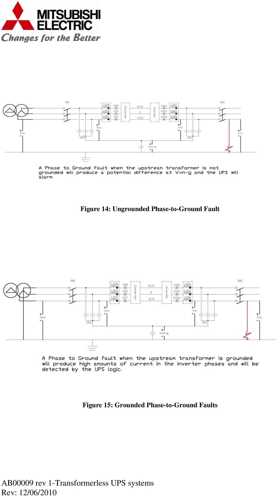
13 The same would apply to a fault on the utility side of the UPS system. The converter logic will sense an immediate drop in voltage and the FPGA will stop firing the IGBTs in the UPS converter going immediately to battery operation. DC Ground Fault Conditions: If a DC Ground fault occurs as in Figure 13, the potential of the system ground will be different than the potential of the Virtual Neutral. This potential difference will be detected by the UPS system and viewed as a safety hazard. The UPS will alarm on a DC Ground Fault condition. The circuit is also being monitored by the chopper circuit logic to detect improper voltages and current levels. Figure 13: DC Ground Fault Ground Fault Detection As shown in Figure 14, if the utility source for the UPS is not grounded (no neutral-to-ground bond), the presence of a ground fault will present a potential difference between the UPS Virtual Neutral and the system ground. Therefore, the fault will be detected by the UPS. As shown if Figure 15, if the utility source for the UPS is grounded (neutral-to-ground bond is installed), the presence of a ground fault will result in a second connection to ground and will produce zero sequence currents. These zero sequence currents will be detected by the UPS.

14 Figure 14: Ungrounded Phase-to-Ground Fault Figure 15: Grounded Phase-to-Ground Faults
15 Figure 16: Phase-to-Phase Faults Summary: The 9900 series UPS is a high efficiency True On-Line Double Conversion transformerless UPS designed specifically for large power applications. It uses an IGBT converter section with advanced control circuitry to eliminate common mode harmonics and leading power factor issues with the upstream generators. The minor and major control loop used with the Digital Signal Processor and the Field Programmable Gate Array for the IGBT inverter results in precise control of the output voltage for maximum coordination with downstream Power Distribution Units and Static Transfer Switches. The Virtual Neutral allows the UPS logic to monitor all types of faults including system ground faults to offer maximum protection for critical loads. The result is a UPS which can deliver reliable output power to your critical load with minimal footprint while saving the customer money through an efficiency of greater than 96% at 100% load. The 9900 is available in sizes ranging from 72 kw to 750 kw (SMS) and up to 3750 kw (MMS). References: The Power of Green: Mitsubishi 9900A Series High Efficiency True On-Line Double Conversion Uninterruptible Power Supply (UPS) by Dean Richards and Junichiro Onishi

UNINTERRUPTIBLE POWER SUPPLIES >9900AUPS UNINTERRUPTIBLE POWER SUPPLIES
 UNINTERRUPTIBLE POWER SUPPLIES 9900A >9900AUPS UNINTERRUPTIBLE POWER SUPPLIES 9900A The 9900A UPS system uses the most advanced IGBT in both the converter and inverter with Digital Signal Processor (DSP)
Line Reactors and AC Drives
 Line Reactors and AC Drives Rockwell Automation Mequon Wisconsin Quite often, line and load reactors are installed on AC drives without a solid understanding of why or what the positive and negative consequences
Principles of Adjustable Frequency Drives
 What is an Adjustable Frequency Drive? An adjustable frequency drive is a system for controlling the speed of an AC motor by controlling the frequency of the power supplied to the motor. A basic adjustable
Harmonics and Noise in Photovoltaic (PV) Inverter and the Mitigation Strategies
 Inverter and the Mitigation Strategies") Soonwook Hong, Ph. D. Michael Zuercher Martinson Harmonics and Noise in Photovoltaic (PV) Inverter and the Mitigation Strategies 1. Introduction PV inverters use semiconductor devices to transform the
Soonwook Hong, Ph. D. Michael Zuercher Martinson Harmonics and Noise in Photovoltaic (PV) Inverter and the Mitigation Strategies 1. Introduction PV inverters use semiconductor devices to transform the
WIND TURBINE TECHNOLOGY
 Module 2.2-2 WIND TURBINE TECHNOLOGY Electrical System Gerhard J. Gerdes Workshop on Renewable Energies November 14-25, 2005 Nadi, Republic of the Fiji Islands Contents Module 2.2 Types of generator systems
City of Leesburg, Florida I.T. Data Center 130551 APPENDIX A TOSHIBA UPS INFORMATION
 City of Leesburg, Florida I.T. Data Center 130551 APPENDIX A TOSHIBA UPS INFORMATION This Appendix A includes technical documents and specifications for the Toshiba 4200 FA 30 kva Uninterruptable Power
Fundamentals of Power Electronics. Robert W. Erickson University of Colorado, Boulder
 Robert W. Erickson University of Colorado, Boulder 1 1.1. Introduction to power processing 1.2. Some applications of power electronics 1.3. Elements of power electronics Summary of the course 2 1.1 Introduction
ELECTRONIC POWER SYSTEMS
 ELECTRONIC POWER SYSTEMS TRADEOFFS BETWEEN SINGLE-PHASE & THREE-PHASE POWER WHITE PAPER: TW0057 1 Executive Summary Modern Electronic Systems are quite often powered from a three-phase power source. While
415V DISTRIBUTION FOR GREEN DATA CENTERS
 White Paper: HMRP-WP001-A5 June 5, 2012 415V DISTRIBUTION FOR GREEN DATA CENTERS Prepared by: Anthony (Tony) Hoevenaars, P. Eng President and CEO Mirus International Inc. Copyright 2012 Mirus International
Product Data Bulletin
 Product Data Bulletin Power System Harmonics Causes and Effects of Variable Frequency Drives Relative to the IEEE 519-1992 Standard Raleigh, NC, U.S.A. INTRODUCTION This document describes power system
Improvements of Reliability of Micro Hydro Power Plants in Sri Lanka
 Improvements of Reliability of Micro Hydro Power Plants in Sri Lanka S S B Udugampala, V Vijayarajah, N T L W Vithanawasam, W M S C Weerasinghe, Supervised by: Eng J Karunanayake, Dr. K T M U Hemapala
Galleon 6-10K Online UPS. Voltronic Power Technology Corporation
 Galleon 6-10K Online UPS Voltronic Power Technology Corporation Features Galleon online UPS series delivers optimal power quality, provides superior power management, resolves utility power protection
Variable Frequency Drives - a Comparison of VSI versus LCI Systems
 Variable Frequency Drives - a Comparison of VSI versus LCI Systems Introduction TMEIC is a leader in the innovative design and manufacture of large ac variable f requency drive systems. TMEIC has been
A MULTILEVEL INVERTER FOR SYNCHRONIZING THE GRID WITH RENEWABLE ENERGY SOURCES BY IMPLEMENTING BATTERY CUM DC-DC CONERTER
 A MULTILEVEL INVERTER FOR SYNCHRONIZING THE GRID WITH RENEWABLE ENERGY SOURCES BY IMPLEMENTING BATTERY CUM DC-DC CONERTER 1 KARUNYA CHRISTOBAL LYDIA. S, 2 SHANMUGASUNDARI. A, 3 ANANDHI.Y 1,2,3 Electrical
Considering the effects of UPS operation with leading power factor loads
 Considering the effects of UPS operation with leading power factor loads Over the past five years, a new generation of data processing and communications equipment has become prevalent in modern data centers
Tamura Closed Loop Hall Effect Current Sensors
 Tamura Closed Loop Hall Effect Current Sensors AC, DC, & Complex Currents Galvanic Isolation Fast Response Wide Frequency Bandwidth Quality & Reliability RoHs Compliance Closed Loop Hall Effect Sensors
Power Electronic Circuits
 Power Electronic Circuits Assoc. Prof. Dr. H. İbrahim OKUMUŞ Karadeniz Technical University Engineering Faculty Department of Electrical And Electronics 1 DC to DC CONVERTER (CHOPPER) General Buck converter
Power Quality. Uninterruptible Power Supply
 Quality Uninterruptible Supply In the electrical system environment, power disturbances will occur. These can be caused by faults on the distribution system, the operation of nearby equipment, lightning
Renewable Energy Applications: Photovoltaic and Wind Energy Conversion Systems (WECS)
") Renewable Energy Applications: Photovoltaic and Wind Energy Conversion Systems (WECS) Josep Pou Antoni Arias Page 1 Outline 1. Renewable Energy Perspectives 2. Solar Photovoltaic (PV) 3. Wind Generation
Renewable Energy Applications: Photovoltaic and Wind Energy Conversion Systems (WECS) Josep Pou Antoni Arias Page 1 Outline 1. Renewable Energy Perspectives 2. Solar Photovoltaic (PV) 3. Wind Generation
Relationship between large subject matter areas
 H02M APPARATUS FOR CONVERSION BETWEEN AC AND AC, BETWEEN AC AND DC, OR BETWEEN DC AND DC, AND FOR USE WITH MAINS OR SIMILAR POWER SUPPLY SYSTEMS; CONVERSION OF DC OR AC INPUT POWER INTO SURGE OUTPUT POWER;
Development of High Frequency Link Direct DC to AC Converters for Solid Oxide Fuel Cells (SOFC)
") Development of High Frequency Link Direct DC to AC Converters for Solid Oxide Fuel Cells (SOFC) Dr. Prasad Enjeti Power Electronics Laboratory Department of Electrical Engineering College Station, TX -
Development of High Frequency Link Direct DC to AC Converters for Solid Oxide Fuel Cells (SOFC) Dr. Prasad Enjeti Power Electronics Laboratory Department of Electrical Engineering College Station, TX -
The full wave rectifier consists of two diodes and a resister as shown in Figure
 The Full-Wave Rectifier The full wave rectifier consists of two diodes and a resister as shown in Figure The transformer has a centre-tapped secondary winding. This secondary winding has a lead attached
LOW COST MOTOR PROTECTION FILTERS FOR PWM DRIVE APPLICATIONS STOPS MOTOR DAMAGE
 LOW COST MOTOR PROTECTION FILTERS FOR PWM DRIVE APPLICATIONS STOPS MOTOR DAMAGE Karl M. Hink, Executive Vice President Originally presented at the Power Quality 99 Conference ABSTRACT Motor protection
Understanding Delta Conversion Online "Power Regulation" - Part 2
 Application Note #40 Understanding Delta Conversion Online "Power Regulation" - Part 2 Introduction This application note is the second in a series on delta conversion theory of operation. For complete
7-41 POWER FACTOR CORRECTION
 POWER FTOR CORRECTION INTRODUCTION Modern electronic equipment can create noise that will cause problems with other equipment on the same supply system. To reduce system disturbances it is therefore essential
Chapter 4. LLC Resonant Converter
 Chapter 4 LLC Resonant Converter 4.1 Introduction In previous chapters, the trends and technical challenges for front end DC/DC converter were discussed. High power density, high efficiency and high power
Control Development and Modeling for Flexible DC Grids in Modelica
 Control Development and Modeling for Flexible DC Grids in Modelica Andreas Olenmark 1 Jens Sloth 2 Anna Johnsson 3 Carl Wilhelmsson 3 Jörgen Svensson 4 1 One Nordic AB, Sweden, [email protected].
SG Series UPS 10-600 kva three phase 400 Vac
 GE Critical Power SG Series UPS 10-600 kva three phase 400 Vac with ultra-high efficiency eboost TM technology imagination at work From protecting assets such as generators, transmission lines and motors,
PowerGem Pro Uninterruptible Power Supply
 Uninterruptible Power Supply User-friendly Intelligent Ultra reliable Range The Most Intelligent On-Line Double Conversion Power Protection System The range achieves higher reliability and greater immunity
VOLTAGE REGULATOR AND PARALLEL OPERATION
 VOLTAGE REGULATOR AND PARALLEL OPERATION Generator sets are operated in parallel to improve fuel economy and reliability of the power supply. Economy is improved with multiple paralleled generators by
AC/DC Power Supply Reference Design. Advanced SMPS Applications using the dspic DSC SMPS Family
 AC/DC Power Supply Reference Design Advanced SMPS Applications using the dspic DSC SMPS Family dspic30f SMPS Family Excellent for Digital Power Conversion Internal hi-res PWM Internal high speed ADC Internal
GE Digital Energy. SG-CE Series UPS. 60-500 kva three phase 400 Vac Uninterruptible Power Supply (UPS) imagination at work
 imagination at work") GE Digital Energy SG-CE Series UPS 60-500 kva three phase 400 Vac Uninterruptible Power Supply (UPS) imagination at work From protecting assets such as generators, transmission lines and motors, to ensuring
GE Digital Energy SG-CE Series UPS 60-500 kva three phase 400 Vac Uninterruptible Power Supply (UPS) imagination at work From protecting assets such as generators, transmission lines and motors, to ensuring
RIELLO ELETTRONICA. Master HP
 RIELLO ELETTRONICA Master HP LOCAL AREA NETWORKS (LAN) SERVERS DATA CENTRES TELECOM- MUNICATIONS DEVICES E-BUSINESS (Servers Farms, ISP/ASP/POP) INDUSTRIAL PROCESSES INDUSTRIAL PLCS ELECTRO- MEDICAL DEVICES
DC TRANSMISSION BASED ON VOLTAGE SOURCE CONVERTERS
 DC TRANSMISSION BASED ON VOLTAGE SOURCE CONVERTERS by Gunnar Asplund, Kjell Eriksson, Hongbo Jiang, Johan Lindberg, Rolf Pålsson, Kjell Svensson ABB Power Systems AB Sweden SUMMARY Voltage Source Converters
Submarine Cable Power Transmission using DC High-Voltage Three-Level Converters
 Submarine Cable Power Transmission using DC High-Voltage Three-Level Converters João Antunes, IST ([email protected]) Astract This paper is about multilevel converters used in High Voltage Direct Current
UNDERSTANDING POWER FACTOR AND INPUT CURRENT HARMONICS IN SWITCHED MODE POWER SUPPLIES
 UNDERSTANDING POWER FACTOR AND INPUT CURRENT HARMONICS IN SWITCHED MODE POWER SUPPLIES WHITE PAPER: TW0062 36 Newburgh Road Hackettstown, NJ 07840 Feb 2009 Alan Gobbi About the Author Alan Gobbi Alan Gobbi
Power Supplies. 1.0 Power Supply Basics. www.learnabout-electronics.org. Module
 Module 1 www.learnabout-electronics.org Power Supplies 1.0 Power Supply Basics What you ll learn in Module 1 Section 1.0 Power Supply Basics. Basic functions of a power supply. Safety aspects of working
TOSHIBA G9000 80/100/160/225 kva
 CORPORATE OFFICE 13131 WEST LITTLE YORK ROAD HOUSTON, TX 77041 PHONE: (713) 466-0277 (800) 231-1412 FACSIMILE: (713) 896-5226 TOSHIBA G9000 80/100/160/225 kva GUIDE SPECIFICATION THREE PHASE UNINTERRUPTIBLE
415V DISTRIBUTION FOR GREEN DATA CENTERS
 White Paper: HMRP-WP001-A1 October 1, 2010 415V DISTRIBUTION FOR GREEN DATA CENTERS Prepared by: Anthony (Tony) Hoevenaars, P. Eng President and CEO Mirus International Inc. Copyright 2005 Mirus International
CEMEP UPS. The high environmental performance solution for power supply to high-availability data centers
 CEMEP UPS The high environmental performance solution for power supply to high-availability data centers Exchanges of information and communication needs are growing at an exponential rate. That growth
Selecting a UPS Topology for your Data Center. by Dr. Daniel Becker, Ph.D., Methode Active Energy Solutions
 Selecting a UPS Topology for your Data Center by Dr. Daniel Becker, Ph.D., Methode Active Energy Solutions Uninterruptible Power Supplies (UPS) are both reaching into new markets and expanding in new ways
GE Digital Energy. SG-CE Series UPS. 60-500 kva three phase 400 Vac Uninterruptible Power Supply (UPS) imagination at work
 imagination at work") GE Digital Energy SG-CE Series UPS 60-500 kva three phase 400 Vac Uninterruptible Power Supply (UPS) imagination at work From protecting assets such as generators, transmission lines and motors, to ensuring
GE Digital Energy SG-CE Series UPS 60-500 kva three phase 400 Vac Uninterruptible Power Supply (UPS) imagination at work From protecting assets such as generators, transmission lines and motors, to ensuring
High-Megawatt Converter Technology Workshop for Coal-Gas Based Fuel Cell Power Plants January 24, 2007 at NIST
 Session 4a Enjeti 1 High-Megawatt Converter Technology Workshop for Coal-Gas Based Fuel Cell Power Plants January 24, 2007 at NIST Dr. Prasad Enjeti TI TI Professor Power Electronics Laboratory College
Multi DIALOG MDM/MDT. MDM 10-20kVA single/single-phase and three/single-phase MDT 10-80kVA three/three-phase NETWORK RANGE
 Local Area Networks (LAN) Servers Data centers Internet centers (ISP/ASP/POP) Industrial PLCs EPOS (Electronic Point of Sale) Systems Emergency devices (lights/alarms) Electro-medical devices Telecommunication
SG Series UPS 10-150 kva. high efficiency systems
 SG Series UPS 10-150 kva high efficiency systems Touching all Areas of the Energy Industry With more than 100,000 employees in over 100 countries, GE s diverse portfolio of products and services is helping
Switch Mode Power Supply Topologies
 Switch Mode Power Supply Topologies The Buck Converter 2008 Microchip Technology Incorporated. All Rights Reserved. WebSeminar Title Slide 1 Welcome to this Web seminar on Switch Mode Power Supply Topologies.
Diode Applications. As we have already seen the diode can act as a switch Forward biased or reverse biased - On or Off.
 Diode Applications Diode Switching As we have already seen the diode can act as a switch Forward biased or reverse biased - On or Off. Voltage Rectifier A voltage rectifier is a circuit that converts an
TOPOLOGIES FOR SWITCHED MODE POWER SUPPLIES
 TOPOLOGIES FOR SWITCHED MODE POWER SUPPLIES by L. Wuidart I INTRODUCTION This paper presents an overview of the most important DC-DC converter topologies. The main object is to guide the designer in selecting
LTR Series Uninterruptible Power Systems 700 VA - 2.1 KVA. General Specification
 08/17/12 Rev2 LTR Series General Specification 700 VA to 2.1 KVA 1.0 General LTR Series Uninterruptible Power Systems 700 VA - 2.1 KVA General Specification This specification describes the features and
AMZ-FX Guitar effects. (2007) Mosfet Body Diodes. http://www.muzique.com/news/mosfet-body-diodes/. Accessed 22/12/09.
 Mosfet Body Diodes. http://www.muzique.com/news/mosfet-body-diodes/. Accessed 22/12/09.") Pulse width modulation Pulse width modulation is a pulsed DC square wave, commonly used to control the on-off switching of a silicon controlled rectifier via the gate. There are many types of SCR s, most
Pulse width modulation Pulse width modulation is a pulsed DC square wave, commonly used to control the on-off switching of a silicon controlled rectifier via the gate. There are many types of SCR s, most
Thyristor-controlled power supplies and battery chargers
 Thyristor-controlled power supplies and battery chargers Input voltage: 115 / 230 VAC, single phase, 50 / 60 Hz or 208 / 400 / 480 VAC, three phases, 50 / 60 Hz Output voltage: 12 / 24 / 48 / 60 / 72 /
GE Digital Energy. TLE Series UPS. 160-400 kw three phase 400 Vac. with best-in-class efficiency. gimagination at work
 GE Digital Energy TLE Series UPS 160-400 kw three phase 400 Vac with best-in-class efficiency gimagination at work GE provides clean, efficient and reliable power for today s digital world with the ultra
Introduction to Power Supplies
 Introduction to Power Supplies INTRODUCTION Virtually every piece of electronic equipment e g computers and their peripherals calculators TV and hi-fi equipment and instruments is powered from a DC power
New High Current MOSFET Module Offers 177 µω R DS(on)
") ew High Current Offers 177 µω R D(on) By William C. Kephart, Eric R. Motto Application Engineering owerex Incorporated Abstract This paper describes a new family of high current modules optimized for industrial
ew High Current Offers 177 µω R D(on) By William C. Kephart, Eric R. Motto Application Engineering owerex Incorporated Abstract This paper describes a new family of high current modules optimized for industrial
DC GROUND FAULT DETECTION PROVIDED FOR UNINTERRUPTIBLE POWER SUPPLIES
 DC GROUND FAULT DETECTION PROVIDED FOR UNINTERRUPTIBLE POWER SUPPLIES Edward P. Rafter, P. E. Principal Tier IV Consulting Group Lee s Summit, Missouri 64064 INTRODUCTION There are concerns among owners
FREQUENCY CONTROLLED AC MOTOR DRIVE
 FREQUENCY CONTROLLED AC MOTOR DRIVE 1.0 Features of Standard AC Motors The squirrel cage induction motor is the electrical motor motor type most widely used in industry. This leading position results mainly
UNDERSTANDING AND CONTROLLING COMMON-MODE EMISSIONS IN HIGH-POWER ELECTRONICS
 Page 1 UNDERSTANDING AND CONTROLLING COMMON-MODE EMISSIONS IN HIGH-POWER ELECTRONICS By Henry Ott Consultants Livingston, NJ 07039 (973) 992-1793 www.hottconsultants.com [email protected] Page 2 THE BASIC
TLE Series UPS 160-800 kva/kw three phase 400 Vac with best-in-class efficiency
 GE Critical Power TLE Series UPS 160-800 kva/kw three phase 400 Vac with best-in-class efficiency imagination at work GE provides clean, efficient and reliable power for today s digital world with the
Simple PWM Boost Converter with I/O Disconnect Solves Malfunctions Caused when V OUT <V IN
 Simple PWM Boost Converter with I/O Disconnect Solves Malfunctions Caused when V OUT
Design and Simulation of Soft Switched Converter Fed DC Servo Drive
 International Journal of Soft Computing and Engineering (IJSCE) ISSN: 2231-237, Volume-1, Issue-5, November 211 Design and Simulation of Soft Switched Converter Fed DC Servo Drive Bal Mukund Sharma, A.
EET272 Worksheet Week 9
 EET272 Worksheet Week 9 answer questions 1-5 in preparation for discussion for the quiz on Monday. Finish the rest of the questions for discussion in class on Wednesday. Question 1 Questions AC s are becoming
Application Information Improving Efficiency in Smart Grid Applications With Fully Integrated Current Sensing ICs
 Application Information Improving Efficiency in Smart Grid Applications With Fully Integrated Current Sensing ICs By Shaun Milano, and Andreas P. Friedrich Allegro MicroSystems Europe Focus on the Photovoltaic
TLE Series. Product Description. 160-200-320-400 kva / 400Vac / S1 KEY BENEFIT APPLICATIONS FEATURES
 TLE Series Product Description 160-200-320-400 kva / 400Vac / S1 KEY BEEFIT High efficiency up to 96.5% in on-line double conversion and 99% in eboost operation mode Unity output power factor; full power
TECHNICAL SPECIFICATIONS FOR 1.5 KVA ONLINE UPS
 Capacity Technology Inverter Technology Noise Level Operating Temperature Humidity Harmonic Distortion Total DC bus voltage Battery recharge time (After Complete discharge) to 100% charge Crest Factor
2012 San Francisco Colloquium
 2012 San Francisco Colloquium http : //www.cigre.org HVDC and Power Electronic Systems for Overhead Line and Insulated Cable Applications B4-8 Trans Bay Cable A Breakthrough of VSC Multilevel Converters
Chapter 6: Converter circuits
 Chapter 6. Converter Circuits 6.. Circuit manipulations 6.2. A short list of converters 6.3. Transformer isolation 6.4. Converter evaluation and design 6.5. Summary of key points Where do the boost, buck-boost,
A Practical Guide to Free Energy Devices
 A Practical Guide to Free Energy Devices Device Patent No 29: Last updated: 7th October 2008 Author: Patrick J. Kelly This is a slightly reworded copy of this patent application which shows a method of
W a d i a D i g i t a l
 Wadia Decoding Computer Overview A Definition What is a Decoding Computer? The Wadia Decoding Computer is a small form factor digital-to-analog converter with digital pre-amplifier capabilities. It is
For a phase-to-phase voltage between 100 V and 1000 V. The standard ratings are: 400 V - 690 V - 1000 V (at 50 Hz)
") 24 1. NETWORK CONFIGURATIONS definition Standard IEC 38 defines voltage ratings as follows: - Low voltage () For a phase-to-phase voltage between 100 V and 1000 V. The standard ratings are: 400 V - 690
24 1. NETWORK CONFIGURATIONS definition Standard IEC 38 defines voltage ratings as follows: - Low voltage () For a phase-to-phase voltage between 100 V and 1000 V. The standard ratings are: 400 V - 690
Evaluating AC Current Sensor Options for Power Delivery Systems
 Evaluating AC Current Sensor Options for Power Delivery Systems State-of-the-art isolated ac current sensors based on CMOS technology can increase efficiency, performance and reliability compared to legacy
Welcome to this presentation on Switch Mode Drivers, part of OSRAM Opto Semiconductors LED Fundamentals series. In this presentation we will look at:
 Welcome to this presentation on Switch Mode Drivers, part of OSRAM Opto Semiconductors LED Fundamentals series. In this presentation we will look at: How switch mode drivers work, switch mode driver topologies,
AN ISOLATED GATE DRIVE FOR POWER MOSFETs AND IGBTs
 APPLICATION NOTE AN ISOLATED GATE DRIVE FOR POWER MOSFETs AND IGBTs by J.M. Bourgeois ABSTRACT Power MOSFET and IGBT gate drives often face isolation and high voltage constraints. The gate drive described
The Facts About Harmonics and Power Factor. Power Quality: Harmonics & Power Factor Correction
 The Facts About Harmonics and Power Factor Power Quality: Harmonics & Power Factor Correction 1 Agenda I. Harmonic Basics II. Harmonic Mitigation Methods III. Active Harmonic Filters IV. Applications V.
PRECISION CAPACITOR CHARGING SWITCHING POWER SUPPLIES
 GENERAL ATOMICS ENERGY PRODUCTS Engineering Bulletin PRECISION CAPACITOR CHARGING SWITCHING POWER SUPPLIES Joe Jichetti, Andrew Bushnell, Robert McDowell Presented at: IEEE Pulsed Power Conference June
VICOR WHITE PAPER. The Sine Amplitude Converter Topology Provides Superior Efficiency and Power Density in Intermediate Bus Architecture Applications
 The Sine Amplitude Converter Topology Provides Superior Efficiency and Power Density in Intermediate Bus Architecture Applications Maurizio Salato, Applications Engineering, Vicor Corporation Contents
Design a Phase Interleaving PFC Buck Boost Converter to Improve the Power Factor
 International Journal of Innovation and Scientific Research ISSN 2351-8014 Vol. 11 No. 2 Nov. 2014, pp. 445-449 2014 Innovative Space of Scientific Research Journals http://www.ijisr.issr-journals.org/
TIG INVERTER INSTRUCTION MANUAL
 TIG INVERTER INSTRUCTION MANUAL Contents Warning General Description Block Diagram Main Parameters Circuit Diagram Installation and Operation Caution Maintenance Spare Parts List Troubleshooting 3 4 4
AN ULTRA-CHEAP GRID CONNECTED INVERTER FOR SMALL SCALE GRID CONNECTION
 AN ULTRA-CHEAP GRID CONNECTED INVERTER FOR SMALL SCALE GRID CONNECTION Pramod Ghimire 1, Dr. Alan R. Wood 2 1 ME Candidate Email: [email protected] 2 Senior Lecturer: Canterbury University
DC UPS. RTB.e 50-1000 A. IMB.e/ITB.e 5-200 kva. E2001.e/E3001.e 5-200 kva. Input voltage: 110/125/220 Vdc. 115/120/230 Vac, 1-phase (IMB.
 Oil & Gas Energy Catalogue DC UPS RTB.e 50-1000 A 3 phase rectifier battery chargers voltage: 400 Vac, 3-phase, 50/60 Hz voltage: 24/48/110/220 Vdc RMB.e/RCB.e 50-100-150 A 1 and 3 phase compact rectifier
How to design SMPS to Pass Common Mode Lightning Surge Test
 Application Note, V1.0, September 2006 How to design SMPS to Pass Common Mode Lightning Surge Test Power Management & Supply N e v e r s t o p t h i n k i n g. Edition 2006-09-06 Published by Infineon
White Paper SolarEdge Three Phase Inverter System Design and the National Electrical Code. June 2015 Revision 1.5
 White Paper SolarEdge Three Phase Inverter System Design and the National Electrical Code June 2015 Revision 1.5 Shalhevet Bar-Asher; SolarEdge Technologies, Inc. Bill Brooks, PE; Brooks Engineering LLC
CYCLOCONVERTERS. Fig.1 Block diagram of a cycloconverter
 CYCLOCONVERTERS Burak Ozpineci, Leon M. Tolbert Department of Electrical and Computer Engineering University of Tennessee-Knoxville Knoxville, TN 37996-2100 In industrial applications, two forms of electrical
What Is Regeneration?
 What Is Regeneration? Braking / Regeneration Manual Regeneration Overview Revision 1.0 When the rotor of an induction motor turns slower than the speed set by the applied frequency, the motor is transforming
Liebert GXT MT+ CX UPS, 1000VA - 3000VA Intelligent, Reliable UPS Protection. AC Power for Business-Critical Continuity
 Liebert GXT MT+ CX UPS, 1000VA - 3000VA Intelligent, Reliable UPS Protection AC Power for Business-Critical Continuity Liebert GXT MT+ CX UPS, 1000VA -3000VA Intelligent, Reliable UPS Protection Liebert
Pulse Width Modulated (PWM)
") Control Technologies Manual PWM AC Drives Revision 1.0 Pulse Width Modulated (PWM) Figure 1.8 shows a block diagram of the power conversion unit in a PWM drive. In this type of drive, a diode bridge rectifier
Control Technologies Manual PWM AC Drives Revision 1.0 Pulse Width Modulated (PWM) Figure 1.8 shows a block diagram of the power conversion unit in a PWM drive. In this type of drive, a diode bridge rectifier
Section 3. Sensor to ADC Design Example
 Section 3 Sensor to ADC Design Example 3-1 This section describes the design of a sensor to ADC system. The sensor measures temperature, and the measurement is interfaced into an ADC selected by the systems
Design of an Auxiliary Power Distribution Network for an Electric Vehicle
 Design of an Auxiliary Power Distribution Network for an Electric Vehicle William Chen, Simon Round and Richard Duke Department of Electrical & Computer Engineering University of Canterbury, Christchurch,
The Different Types of UPS Systems
 Systems White Paper 1 Revision 6 by Neil Rasmussen Contents Click on a section to jump to it > Executive summary There is much confusion in the marketplace about the different types of UPS systems and
IGBT Protection in AC or BLDC Motor Drives by Toshio Takahashi
 International Rectifier 233 Kansas Street, El Segundo, CA 90245 USA IGBT Protection in AC or BLDC Motor Drives by Toshio Takahashi The new IR2137 IGBT Gate Driver IC integrates Ground Fault and Over-Current
Technical Comparison of On-line vs. Line-interactive UPS designs
 Technical Comparison of On-line vs. Line-interactive UPS designs By Jeffrey Samstad Michael Hoff White Paper #79 Executive Summary UPS systems below 5000VA are available in two basic designs: line-interactive
Power Quality Issues, Impacts, and Mitigation for Industrial Customers
 Power Quality Issues, Impacts, and Mitigation for Industrial Customers By Kevin Olikara, Power and Energy Management Products Rockwell Automation, Inc. Now, more than ever, electronic equipment and computing
SECTION 26 29 23 VARIABLE FREQUENCY DRIVES
 SECTION 26 29 23 VARIABLE FREQUENCY DRIVES PART 1 GENERAL 1.01 SCOPE A. Furnish and install individual freestanding variable frequency AC drives (VFD) as shown on the Drawings and specified herein. 1.02
Simulation and Analysis of PWM Inverter Fed Induction Motor Drive
 Simulation and Analysis of PWM Inverter Fed Induction Motor Drive C.S.Sharma, Tali Nagwani Abstract Sinusoidal Pulse Width Modulation variable speed drives are increasingly applied in many new industrial
Pulse Width Modulated (PWM) Drives. AC Drives Using PWM Techniques
 Drives. AC Drives Using PWM Techniques") Drives AC Drives Using PWM Techniques Power Conversion Unit The block diagram below shows the power conversion unit in Pulse Width Modulated (PWM) drives. In this type of drive, a diode bridge rectifier
Drives AC Drives Using PWM Techniques Power Conversion Unit The block diagram below shows the power conversion unit in Pulse Width Modulated (PWM) drives. In this type of drive, a diode bridge rectifier
8 coil stator 11 coil stator
 Below is a schematic of a typical scooter electrical set up as far as the stator, CDI, rectifier/regulator go along with the other items running on the electrical system; This is the 6 coil stator common
3-Phase Synchronous PWM Controller IC Provides an Integrated Solution for Intel VRM 9.0 Design Guidelines
 3-Phase Synchronous PWM Controller IC Provides an Integrated Solution for Intel VRM 9.0 Design Guidelines Odile Ronat International Rectifier The fundamental reason for the rapid change and growth in information
Single-Stage High Power Factor Flyback for LED Lighting
 Application Note Stockton Wu AN012 May 2014 Single-Stage High Power Factor Flyback for LED Lighting Abstract The application note illustrates how the single-stage high power factor flyback converter uses
Low Cost Pure Sine Wave Solar Inverter Circuit
 Low Cost Pure Sine Wave Solar Inverter Circuit Final Report Members: Cameron DeAngelis and Luv Rasania Professor: Yicheng Lu Advisor: Rui Li Background Information: Recent rises in electrical energy costs
1ED Compact A new high performance, cost efficient, high voltage gate driver IC family
 1ED Compact A new high performance, cost efficient, high voltage gate driver IC family Heiko Rettinger, Infineon Technologies AG, Am Campeon 1-12, 85579 Neubiberg, Germany, [email protected]