Programmable Room Thermostat 7 Day (5-2 Day) Models: / Power Supply: Battery / Mains
|
|
|
- Theresa Conley
- 9 years ago
- Views:
Transcription
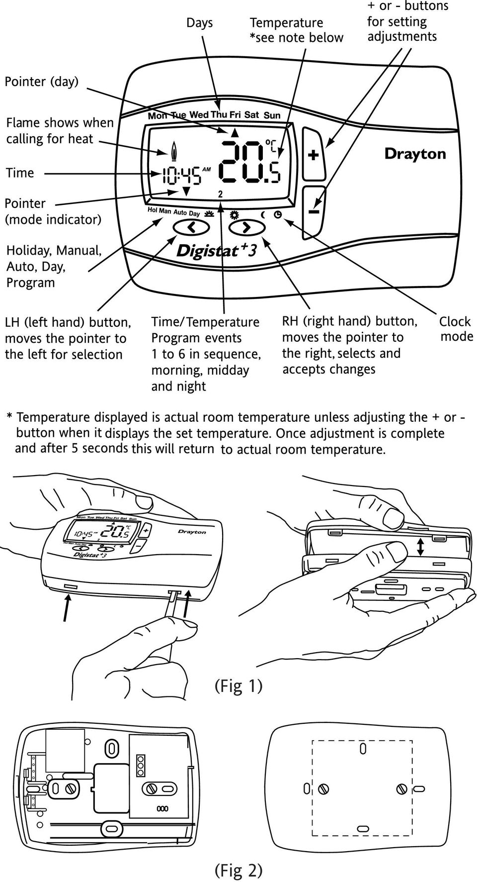
1 Drayton Programmable Room Thermostat 7 Day (5-2 Day) Models: / Power Supply: Battery / Mains Invensys Controls Europe Technical Helpline: +44 (0) Installation / User Guide (0905)
")
2 Installation Guide Warning If you do not have the knowledge to install the Digistat+3 safely, arrange for a competent electrician to install it for you. Wiring should conform to the current IEE wiring regulations. Isolate mains supply before removing an existing room thermostat and fitting Digistat+3. Digistat+3 programmable room thermostats are double insulated therefore Neutral and Earth connections are not required. Unused existing cables should be safely insulated. Location Care should be taken to mount the Digistat+3 on a wall, in a postion which is not subject to direct sunlight or draughts. Preferably it should be mounted on an inside wall about 1.5M (5ft) above the floor in a position where it can respond to room temperature but away from the direct influence of radiators or other appliances giving off heat. Installation 1. Remove the front cover using a flat screwdriver and separate from back plate (Fig 1). 2. Fix the back plate directly onto the wall using suitable wall plugs and screws or mount over existing wall box (Fig 2). 3. Complete the wiring according to the connection suggestions shown in Fig 3. For Basic boiler, Combi boiler and Basic boiler with zone valve applications Digistat+3 with battery or mains supply are suitable. For Electric Heat application use Digistat+3 with mains supply only. 4. Replace the front cover by locating in position and pushing fully onto the back cover (Fig 4). 5. Remove the battery cover using a coin (Fig 5). Battery model only. 6. Install the 2 AA batteries provided (Fig 6). Battery model only. 7. Replace battery cover (fig 7). Battery model only. 8. The Digistat+3 is now installed and will automatically start to control the room temperature according to the pre-set program 1 as shown in the User Guide. The display shows the correct time and date which is automatically set together with the actual room temperature. (Fig 4)

3 (Fig 1) (Fig 2)
4 (Fig 3) (Fig 6) (Fig 5) (Fig 7) T
 T")
5 Installation Guide continued Installer Options. If you wish to change any of the Installer Options as shown below, enter the Installer Option Menu from Auto mode by pressing < and + simultaneously for 5 seconds. Pressing < and + again for 5 seconds will exit the Menu and return to Auto mode. Once the Installer Options screen has been selected (Fig 8), the < and > buttons allow you to scroll through the Menu (shown below). The + and - allow you to change values. Once a value has been changed pressing > before exiting the Menu will save the new setting. (Fig 9 shows Option 1 OFF). (Fig 8) (Fig 9) Installer Options What is it Select between Default 1 Access protection lock On Off Off 2 Freeze protection On Off On 3 Low limit set point ºC 7 High limit 7 4 High limit set point ºC Low limit Delayed start (Energy saving feature) On Off Off 6 Valve protection On Off Off 7 Valve protection time (Mins) Sensor fault function On Off Off 9 Application type Access protection lock. The access protection lock allows the installer to lock the Digistat+3 so that the user cannot make any adjustments. The default is OFF mode allowing the users to adjust the Digistat+3 (see User Guide). To Lock the Digistat+3 settings enter the Installer Options Menu (Refer to Installer Option 1) and select On and press > to accept. Once the Installer Options Menu is exited all buttons will be locked. To switch off the Protection Lock enter the Installer Menu and change to OFF. Press > to accept. Once the Installer Menu is exited all buttons will be free to adjust. F
, the < and > buttons allow you to scroll through the Menu (shown below). The + and - allow you to change values.")
6 Freeze protection. Freeze protection will switch on the heating if the room temperature falls to 5ºC and will then control the temperature at 7ºC even if the Digistat+3 is in OFF mode. The freeze protection default is ON. To switch off the Freeze protection mode enter the Installer Options Menu (Refer to Installer Options 2) and change to OFF. Press > to accept. Low and High Limit set points. The user temperature set points defaults are High 32ºC and Low 7ºC, to change these limits enter the Installer Options Menu (Refer to Installer Options 3 & 4). Intelligent Delayed Start (Energy saving feature). The Intelligent Delayed Start is an energy saving feature which automatically reduces the warm up time for the heating system. As the weather becomes milder, Intelligent Start will delay the heating start times so that fuel is not wasted bringing the room up to temperature earlier than necessary. Note: Intelligent Delayed Start only applies in Auto mode. Intelligent Delayed Start default is in OFF mode. To switch on Intelligent Delayed Start enter the Installer Options Menu (Refer to Installer Options 5). Note the Intelligent Delayed start option is not suitable for Hydronic underfloor application. Ensure Installer option 5 is set to Off before final commissioning for Hydronic underfloor application. Valve protection. In some hydronic heating systems there may be a requirement to protect the valve by operating it once a day, for a given period without bringing on the heating system. If valve protection is selected the valve will be operated for a period as shown in Valve protection time (mins). Valve protection time every day at 10.00am. Valve protection default is OFF. To enable the valve protection mode enter the Installer Options Menu (Refer to Installer Option 6) Valve protection time (mins). Valve protection time can be set between 1 and 5 minutes (default 3 minutes) To change this once a day on time enter the Installer Options Menu (Refer to Installer Option 7).
. The Intelligent Delayed Start is an energy saving feature which automatically reduces the warm up time for the heating system.")
7 Sensor fault function. When the display shows an error code (E1) or (E2) this indicates a sensor fault and the heating system will remain Off. (E1) = internal sensor and (E2) = external sensor. If (E1) is shown the Digistat+3 should be replaced. If (E2) is shown, first check the external sensor terminal block connections before replacing the Digistat+3. Sensor fault function allows you to temporally set the Digistat+3 to cycle the heating system 30% On and 70% Off until you have replaced the product. This can be done by entering the installer Option Menu (Option 8) and selecting On. Press > to accept. To reset to default Off, entering the installer Option Menu (Option 8) and selecting Off. Press > to accept. Application type. Model (Battery) can be used for radiator or Hydronic underfloor applications. In installer Option select: 0 = Radiator. 1 = Hydronic underfloor. Default 0 = Radiator. Model (Mains) can also be used for electric heat applications. 0 = Radiator and electric heat. 1 = Hydronic underfloor. To change application enter the installer Option Menu and refer to (Option 9). Drayton Digistat+3 7 day 5:2 day Programmable Room Thermostat Allowing different programs for weekdays and weekends and also every day of the week can be programmed differently.
 and selecting On. Press > to accept. To reset to default Off, entering the installer Option Menu (Option 8) and selecting Off.")
8 Technical Data Model Power supply 2 X AA 1.5V 230V AC 50Hz alkaline batteries Battery life 3 years typical Switch rating Heating (switch N.O.) Switch type Min. recommended current 16(2)A 230 Vac SPDT (voltage free contacts) (inductive) Ambient temperature Operating 0 C to 50 C Storage 20 C to 85 C Ambient humidity Operating 25% to 85% (non condensing). Storage 15% to 95% Temperature range 0 C to 32 C Accuracy (between 7 C & 32 C) 0.5 C Timing resolution Temperature resolution Rated impulse voltage 1 minute 0.1 C 2.5KV Ball pressure test 75 C Pollution situation Degree 2 Protection level Wiring: IP30 Designed for fixed wiring only, to comply with IEE wiring regulations Dimensions 96.5 Hol Man Auto Day

Drayton Digistat +2RF/+3RF
 /+3RF Programmable Room Thermostat Wireless Model: RF700/22090 Model: RF701/22092 Power Supply: Battery - Thermostat Mains - Digistat SCR Invensys Controls Europe Customer Service Tel: 0845 130 5522 Customer
Drayton Digistat +2RF
 Drayton Digistat +2RF T Programmable Room Thermostat Wireless 24 Hour Model: RF700/22090 Power Supply: Battery - Thermostat Mains - Digistat SCR Invensys Controls Europe Customer Service Tel: 0845 130
TRANSMITTER RECEIVER THESE INSTRUCTIONS APPLY IN THE UK ONLY THESE INSTRUCTIONS ARE TO BE LEFT WITH THE USER OR AT THE APPLIANCE. Digistat Optimiser
 FITTING AND OPERATING INSTRUCTIONS FOR DIGISTAT OPTIMISER PROGRAMMABLE 7 DAY ROOM THERMOSTAT SYSTEM General information is given in the users instruction leaflet despatched with the appliance and/or on
RDJ10RF/SET. Wireless room temperature controller with 24-hour time switch and LCD. Programmable, for heating systems
 3 072 RDJ10RF RCR10/433 Wireless room temperature controller with 24-hour time switch and LCD Programmable, for heating systems RDJ10RF/SET Operating modes: Automatic, Comfort, Energy Saving, and Frost
Wireless 7 Day Programmable Room Thermostat
 Wireless 7 Day Programmable Room Thermostat Cat. No. TRT037 Transmitter Receiver Operating & Installation Instructions What is a programmable room thermostat? an explanation for householders A programmable
CM702 PROGRAMMABLE THERMOSTAT FEATURES PRODUCT SPECIFICATION SHEET
 CM702 PROGRAMMABLE THERMOSTAT FEATURES Attractive slim, modern styling makes it ideal for location in any type of home. 24-hour heating program. Up to 4 daily independent time and temperature level changes
COMPUTHERM Q7 Programmable, digital room thermostat. Operating Instructions
 COMPUTHERM Q7 Programmable, digital room thermostat Operating Instructions GENERAL DESCRIPTION OF THE THERMOSTAT The COMPUTHERM Q7 type switched-mode room thermostat is suitable to regulate the overwhelming
User Manual THR840DUK Digital Thermostat
 User Manual THR840DUK Digital Thermostat 50051982-001 Rev. A WARNING: This product must be correctly installed and configured to work properly (see pages 12-24). If you are not experienced in wiring electrical
Alpha Climatic Programmable Modulating Boiler Energy Manager. Installation and User Instructions
 Alpha Climatic Programmable Modulating Boiler Energy Manager Part No 3.022144 (Hard Wired) Part No 3.022143 (Radio Frequency) Installation and User Instructions 1. Description The Alpha Climatic energy
DUAL SENSING DIGITAL THERMOSTAT PRODUCT INSTRUCTIONS. Construction Automotive Industry
 DUAL SENSING DIGITAL THERMOSTAT PRODUCT INSTRUCTIONS www.rehau.com Construction Automotive Industry SCOPE This guide gives instruction regarding REHAU Programmable Digital Thermostat installation and operation.
Owner s Guide Guide du propriétaire Guía para el usuario TH115-AF-GB-10. Programmable thermostat Thermostat programmable Termostato programable
 Owner s Guide Guide du propriétaire Guía para el usuario TH115-AF-GB-10 Programmable thermostat Thermostat programmable Termostato programable Read and save these instructions. Veuillez lire le mode d
RF 1. Contents: Connecting diagram. Detailed information:
 Contents: Introduction UFH-ZONE-R UFH-EXTRAZONE -R Connection of a thermostat (UFH-THERM-R) o Joining of a thermostat with UFH-ZONE-R or UFH-EXTRAZONE-R Connection of a digital thermostat (UFH-THERM -RD)
Fused Spur Time Switch
 Fused Spur Time Switch Model No. FST24 24 Hour Timer Model No. FST77 7 Day Timer Installation & Operating Instructions 1. General Information Illuminated screen Sets programmes Sets time and date Reset
Operating instructions for built-in electronic timers with Day and Week programms. Series 884
 Operating instructions for built-in electronic timers with Day and Week programms Series 884 Attention: This operating manual is destined for our OEM customers and is intended as a basis for the instruction
TP5000 Si Range Electronic 5/2 day programmable room thermostat Mains, Battery and RF versions Installation and User Instructions
 TP5000 Si Range Electronic 5/2 day programmable room thermostat Mains, Battery and RF versions Certification Mark GB Installation and GB Index Index Installation Instructions 3-14 Product Specification
Vroom Hardware manual ver. 1.00 Code 114VROOHWE00. Vroom CANBUS USER INTERFACE WITH LCD GRAPHIC DISPLAY AND WITH TEMPERATURE AND HUMIDITY SENSOR
 Vroom CANBUS USER INTERFACE WITH LCD GRAPHIC DISPLAY AND WITH TEMPERATURE AND HUMIDITY SENSOR ENGLISH HARDWARE MANUAL ver. 1.00 CODE 114VROOHWE00 page 1 of 22 Important Important Read these instructions
DC1100 & 1400 Energy Controllers. Satchwell DC1100 & DC1400 for energy-efficient temperature control in smaller buildings.
 1100 & 1400 Energy Controllers Satchwell 1100 & 1400 for energy-efficient temperature control in smaller buildings. 02 1100 & 1400 Energy Controllers Features he 1100 and 1400 Energy Controllers are self-configuring
Nest Learning Thermostat Installation Guide. Installation step-by-step
 Nest Learning Thermostat Installation Guide Installation step-by-step Contents Compatibility. 3 In the box. 4 Before you start. 5 Choose an installation method. 6 Replacing an existing wired thermostat.
Installation Guide for Hive Active Heating
 Installation Guide for Hive Active Heating Important note: Installation should only ever be carried out by a qualified engineer. Technical Support If you need to contact Hive s Technical Support team during
Manual & Technical Documentation V1.1
 Manual & Technical Documentation V1.1 tado Smart Thermostat tado Extension Kit ENGLISH Content Product Packages Compatibility Intelligence & Security Functions Smart Thermostat Usage Menu Structure Special
Current valve. for AC 24 V pulse/pause control of electrical loads up to 30 kw
 4 937 DESIO Current valve for AC 24 V pulse/pause control of electrical loads up to 30 kw SEA45.1 Use The current valve is used for the control of electric heating elements in heating, ventilation and
T0118 T2118 T3118. Instruction Manual
 Programmable indoor transmitter of temperature T0118 Programmable indoor transmitter of atmospheric pressure T2118 Programmable indoor transmitter of temperature, relative humidity and other derived humidity
OPERATING INSTRUCTIONS
 24 HOUR IMMERSION HEATER TIME CONTROLLER Cat. No TS900B OPERATING INSTRUCTIONS TS900B 24 Hour Immersion Heater Time Controller 24 hour programme ring Self-cancelling and Override switch Setting pins Time
Installation & User Instructions
 103 electro-mechanical 24 hour timeswitch for controlling hot water and heating Installation & User Instructions including Factory Replacement Units (FRU) Certification Mark This product complies with
HERZ-Thermal Actuators
 HERZ-Thermal Actuators Data Sheet 7708-7990, Issue 1011 Dimensions in mm 1 7710 00 1 7710 01 1 7711 18 1 7710 80 1 7710 81 1 7711 80 1 7711 81 1 7990 00 1 7980 00 1 7708 11 1 7708 10 1 7708 23 1 7709 01
MAKING MODERN LIVING POSSIBLE. living connect. Installation and User Guide. Danfoss Heating Solutions
 MAKING MODERN LIVING POSSIBLE living connect Installation and User Guide Danfoss Heating Solutions 2 living connect Thank you for buying a Danfoss product Danfoss Heating Solutions 3 Contents 1. System
evohome Wireless Radiator Zoning Kit Installation & User Guide
 evohome Wireless Radiator Zoning Kit Installation & User Guide Getting the most from your evohome system Installation & User Guide 1 Getting the most from your evohome system Thanks for choosing an evohome
Installation Guide. VisionPRO. TH8000 Series. Need Help? This manual covers the following models. System Types
 Installation Guide VisionPRO TH8000 Series Touch-screen Programmable Thermostat This manual covers the following models TH8110U: For 1 Heat/1 Cool systems TH8320U: For up to 3 Heat/2 Cool systems TH8321U:
TABLE 1: Wiring Terminals. Connect to... 1C 1H 2C 2H 1H1C 2H1C 2H2C 3H2C
 Installation TURN OFF POWER TO THE SYSTEM AT THE MAIN POWER PANEL TO AVOID ELECTRICAL SHOCK. Installation should be carried out by an electrician or a qualified technician. 1.1 Find a Location for the
Introduction. Refrigerant Leak Detecting System. Feature and Benefits
 PSC European Refrigeration Controls Catalogue Catalog Section 9 Product Bulletin PD-GAS-E Refrigerant Leak Detecting System Introduction This range of refrigerant leak detecting systems is designed for
Rain+Birdt. Simple To Set Timer (SST) Setup & Operation Instructions. English. 1-800- RAIN BIRD (800-724-6247) or visit www.rainbird.
 Setup & Operation Instructions. English. 1-800- RAIN BIRD (800-724-6247) or visit www.rainbird.") Rain+Birdt Simple To Set r (SST) Setup & Operation Instructions English Installation...2 Tools and Supplies Needed...2 Step 1. Mount r...2 Step 2. Connect Power...2 Indoor r...2 Outdoor r...2 Step 3. Connect
Rain+Birdt Simple To Set r (SST) Setup & Operation Instructions English Installation...2 Tools and Supplies Needed...2 Step 1. Mount r...2 Step 2. Connect Power...2 Indoor r...2 Outdoor r...2 Step 3. Connect
SET1E. Installation & User Instructions. Electronic timeswitch for heating & hot water. Certification Mark
 SET1E Electronic timeswitch for heating & hot water Installation & User Instructions Certification Mark Index INDEX Installation Product specification 3 Installation 4-5 Wiring 5-10 Replacement 11-13 User
T7560A,B,C Digital Wall Module
 T7560A,B,C Digital Wall Module HONEYWELL EXCEL 5000 OPEN SYSTEM BEFORE INSTALLATION All wiring must comply with local electrical codes and ordinances or as specified on installation wiring diagrams. Digital
Wireless Thermostats 230v and Battery Operated Instruction Manual
 Wireless Thermostats 230v and Battery Operated Instruction Manual For models: JGSTATW2W JGSTATW2B JGSTATW1W JGSTATW1B Contents Box contents: Wireless Thermostats 230v and Battery Operated Instruction Manual
USERS GUIDE. LOGIC Combi 24, 30, 35. For installation guide see reverse of book
 USERS GUIDE LOGIC Combi 24, 30, 35 For installation guide see reverse of book When replacing any part on this appliance, use only spare parts that you can be assured conform to the safety and performance
its ELECTRIC POSITION for electric heat, or set the units fan control appropriately to ELECTRIC or another appropriate setting.
 Troubleshooting Poor Temperature Regulation This page lists problems that may affect the temperature performance of your LUX thermostat with suggested resolutions. For more detailed information please
Sensi TM. Wi-Fi Programmable Thermostat MANUAL OPERATION. Version: March 2016 2016 Emerson Electric Co. All rights reserved.
 Sensi TM Wi-Fi Programmable Thermostat MANUAL OPERATION Version: March 2016 2016 Emerson Electric Co. All rights reserved. Contents MANUAL OPERATION GUIDE Buttons and Icons 3 Basic Functionality 4 Manual
THERMONET UNDERFLOOR HEATING STANDARD THERMOSTAT KIT STOCK CODE 5260
 THERMONET UNDERFLOOR HEATING STANDARD THERMOSTAT KIT STOCK CODE 5260 STANDARD THERMOSTAT KIT 1.0 KIT CONTENTS Parts included: 1 x Thermostat 1 x Wall plate 2 x Mounting box screws 1 x Floor temperature
AN500T, AN1000, AN1000T, AN1500, AN1500T AN2000, AN2000T
 Product Instruction Manual Accona AN500T, AN1000, AN1000T, AN1500, AN1500T AN2000, AN2000T Panel heater v16.5/5 Version 3.2 Jan 2015 Contents 1. Important safety points 2. Installation 2.1. Wall mounting
ES-LCD User Control SD Card Location
 SD Card Location Addendum to Leaflet Number 671415 The EMC Directive 2004/108/EC The Low Voltage directive 2006/95/EC Checking SD Card for secure location Due to the possibility of movement during transit,
Inductive Sensors Single or Dual Loop Detectors Type LD with teach-in
 Inductive Sensors Single or Dual Loop Detectors Type LD with teach-in Single or Dual loop detector Automatically adjustment of detection level Manual sensitivity for compensations of variations Easy installation
GB/DAS User Instruction
 GB/DAS User Instruction devireg 540/550 Table of contents Introduction 3 Introducing devireg 540/550 4 How to use your deviheat heating system 6 Daily operation 7 Setting the clock & day 10 Timer programming
MAKING MODERN LIVING POSSIBLE. living connect. Installation and User Guide. Danfoss heating
 MAKING MORN LIVING POSSIBLE Danfoss heating living connect Installation and User Guide Contents 1.0 System overview... 3 2.0 Overview of display and control buttons... 3 3.0 Installation - step by step...
Daker DK 1, 2, 3 kva. Manuel d installation Installation manual. Part. LE05334AC-07/13-01 GF
 Daker DK 1, 2, 3 kva Manuel d installation Installation manual Part. LE05334AC-07/13-01 GF Daker DK 1, 2, 3 kva Index 1 Introduction 24 2 Conditions of use 24 3 LCD Panel 25 4 Installation 28 5 UPS communicator
VIESMANN. Installation and service instructions VITOTROL 100. for contractors
 Installation and service instructions for contractors VIESMANN Vitotrol 100 Type UTDB-RF2 Room temperature controller with digital time switch and wireless receiver For applicability, see the last page
DS 1.102 DRTE. AIR ROOM TEMPERATURE SENSOR with fan speed control switches
 DS 1.102 02/99 AIR ROOM TEMPERATURE SENSOR with fan speed control switches Specification No. 528-X-XXX* The Active Room Temperature sensor incorporating fan speed control switches is designed to give a
RVL470. Heating Controller. Building Technologies HVAC Products. Series B
 2 522 Heating Controller Series B RVL470 Multifunctional heating controller for use in residential and non-residential buildings; suitable for weather-dependent flow temperature control of heating zones
Operating Instructions DT, PRT, PRT/HW PRT-R, PRT-R2
 Operating Instructions DT, PRT, PRT/HW PRT-R, PRT-R2 Heatmiser UK td Tel: +44(0)1254 776343 Primrose House www.heatmiser.co.uk Primrose Street Darwen ancashire BB3 2DE Contents Contents 1 Installation
Portable Air Conditioner
 Portable Air Conditioner Owner's Manual Model:3 in 1 12,000 Btu/h Series 3 Please read this owner s manual carefully before operation and retain it for future reference. CONTENTS 1. SUMMARY...1 2. PORTABLE
Installation Guide. DEVIreg 530. Electronic Thermostat. www.devi.com
 Installation Guide DEVIreg 530 Electronic Thermostat www.devi.com The English language is used for the original instructions. Other languages are a translation of the original instructions. (Directive
www.sebury.com.cn Digital Keypad Use s Manual
 K3 K4 www.sebury.com.cn Digital Keypad Use s Manual Contents Introduction Introduction Specifications Intramural Interface Circuit 3 Mounting 3 Wiring 5 Power UP 7 Engineer Programming Mode 7 The K3/K4
Install Guide CT100. Caution. Caution ENGLISH. disconnect the power supply before beginning work.
 Install Guide CT100 PG 1 Caution top cover Your thermostat is a precise instrument, handle it with care. Turn off electricity to the system before installing or servicing thermostat or any part of the
HCE80/HCC80/HCE80R/HCC80R
 HCE80/HCC80/HCE80R/HCC80R UNDERFLOOR HEATING-ZONEING CONTROLLERS PRODUCT DATA FEATURES Easy and fast installation because the new wiring design Pluggable terminals for fast wiring connection because clamp
DT92 WIRELESS DIGITAL ROOM THERMOSTAT FEATURES PRODUCT SPECIFICATION SHEET
 DT92 WIRELESS DIGITAL ROOM THERMOSTAT PRODUCT SPECIFICATION SHEET The new DT92 family of wireless digital room thermostats is a range of market leading products designed to provide comfort with economy
PD 100A. Printing data system
 PD 100A Printing data system Operating instructions ENGLISH IMPORTANT: Read these instructions carefully before installing and using the device; do not forget following all additional information. Keep
Adjustable room thermostat for heating only or cooling only systems
 3 003 Room hermostat RAA30 Adjustable room thermostat for heating only or cooling only systems Room thermostat with manual O/OFF switch wo-position control witching voltage AC 24 250 V Use he RAA30 room
Digital timer thermosatat. isense. Installation and Service Manual 120666-AG
 EN Digital timer thermosatat isense Installation and Service Manual 120666-AG Contents 1 Preface...4 1.1 General...4 2 Location of the installation...5 2.1 Position of the regulator...5 2.2 Installation
USER S MANUAL HSC-24A
 AIRREX AIR CONDITIONER USER S MANUAL HSC-24A Thank you for purchasing an AIRREX AIR CONDITIONER. BEFORE operation please read this user s manual carefully. Keep this manual readily available. It is ESSENTIAL
Baxi Combi 130 HE. User s Operating Instructions. Gas Fired Wall Mounted Condensing Combination Boiler
 User s Operating Instructions Baxi Combi 130 HE Gas Fired Wall Mounted Condensing Combination Boiler Please keep these instructions safe. Should you move house, please hand them over to the next occupier.
Type: EASY719 DC RC Article No.: 274119. Ordering information Relay outputs Quantity 6 Power supply V DC 24 V DC. Description
 Type: EASY719 DC RC Article.: 274119 Ordering information Relay outputs Quantity 6 Power supply V DC 24 V DC Description 12 digital inputs (4 inputs available as analog inputs) 6 relay outputs LCD display
OZW30. Central Unit SYNERGYR
 2 841 SYNERGYR Central Unit OZW30 Collects billing data from the apartments. Generates an image of each apartment's heat consumption and makes it available for readout. Acts on room temperature control
Heating Controller. Building Technologies HVAC Products
 2 474 Heating Controller RVP300 Multifunctional heating controller for use in residential and non-residential buildings; suitable for weather-dependent flow temperature control of heating zones with or
Table of Contents. 1 - Specifications...3. 2 - Installation...3. 3 - Wiring...5. 4 - User controls...7
 THERMOSTATS Table of Contents Page 1 - Specifications...3 1.1 - Product range...3 ARTTH001 (DSL-610)...3 ARTTH002 (DSL-700)...3 ARTTH003 (DSL-600)...3 1.2 - Technical data...3 1.3 - Power failures...3
Operating Instructions. Room temperature controller
 Operating Instructions 1. Area of application The room temperature controller is used to regulate the temperature in closed rooms such as flats, schools, function suites, workshops, etc. Safety instructions
Installation Guide. Programmable Thermostat TH6220D
 Installation Guide Programmable Thermostat TH6220D Product Application This thermostat provides electronic control of 24 VAC single-stage and multi-stage heating and cooling systems, or 750 mv heating
IDEAL INDUSTRIES, INC. TECHNICAL MANUAL MODELS: 61-763 61-765
 IDEAL INDUSTRIES, INC. TECHNICAL MANUAL MODELS: 61-763 61-765 The Service Information provides the following information: Precautions and safety information Specifications Performance test procedure Calibration
Model UT713 OPERATING MANUAL
 Model UT713 OPERATING MANUAL TABLE OF CONTENTS TITLE PAGE Introduction Unpacking Inspection Safety Information Turning the Calibrator On Simulating a Thermocouple Measuring a Thermocouple Simulating TC
ELECTRIC CENTRAL HEATING FLOW BOILER
 ELECTRIC CENTRAL HEATING FLOW BOILER EKCO.T Used product can t be treated as general communal waste. Disassembled appliance has to be delivered to the collection point of electrical and electronic equipment
Max primary circuit temperature 90ºC Max primary circuit temp. 90ºC Max secondary circuit temperature 45ºC Max secondary circuit temp.
 EGLISH 1 Product description exchanger equipped with an electronic control unit and circulation pump for the primary circuit. All Aqua-Mex variants can be ordered with an interior coil of either titanium
ELECTRIC POSITION for electric heat, then confirm with Fan Test below.
 Troubleshooting Poor Temperature Regulation This page lists problems that may affect the temperature performance of your LUX thermostat with suggested resolutions. For more detailed information please
2.0 Installation 1. Remove the cover using a small flat blade screwdriver. Figure 2: Cover Removal
 O N DS160/DS161 Installation Guide High Performance Request-to-Exit Sensors 1.0 Description The DS160/161 is a passive-infrared (PIR) detector designed for Request to Exit (REX) interior applications.
Duct Humidity Transmitter
 SDC-H Duct Humidity Transmitter Features Replaceable sensor element Humidity measurement for air ducts Minimum and maximum value memory 0 0V, 0 0mA or 0V, 4 0mA measuring signals selectable with jumpers
REB 1 REB 3 REB 5 REB 6 REB 8 REB 10 REB 12 REB 16
 REB 1 REB 3 REB 5 REB 6 REB 8 REB 10 REB 12 REB 16 Manually Operated Electronic Speed Controller Single Phase For all applications using suitably specified single-phase induction motor fans 1 GENERAL The
Table of Contents. Introduction. Radio Frequency Control. Initial setup Setting the time. Setting the temperature
 LHZ USER GUIDE LHZ User Guide LHZ would like to thank you for purchasing your LHZ radiator. You have purchased a high quality, German designed and manufactured heating device, which will give you soft
RM17TE 183...528 V AC. Main. Product or component type. Product specific application. Relay monitored parameters 250 V DC 5 A DC
 Characteristics multifunction control relay RM17-TE - range 183..528 V AC Complementary Reset time Maximum switching voltage Minimum switching current Maximum switching current [Us] rated supply voltage
SET3M. electro-mechanical 24 programmer for heating & hot water. Installation & User Instructions
 SET3M electro-mechanical 24 programmer for heating & hot water Installation & User Instructions Index Installation Product specification 3 Installation 4-5 Wiring 6-12 Replacement 13-15 User Your programmer
For installation guide see reverse of book
 USERS GUIDE LOGIC Combi 24, 30, 35 For installation guide see reverse of book When replacing any part on this appliance, use only spare parts that you can be assured conform to the safety and performance
Installation and User Guide
 Installation and User Guide 458-UNI8 8-Channel Universal Dimmer Module Introduction The 458/UNI8 is an 8-channel universal, digital transistor, dimmer module. Each channel s mode can be selected for either
Product and Applications Description. Application Programs. Example of Operation. GAMMA instabus Technical Product-Information.
 Product and Applications Description The power supply units N 125/x2 can supply DC 24 V power from an additional pair of terminals (yellowwhite). This DC 24 V output voltage can be used to power e.g. an
ELITE-L Series. ELITE - Low Voltage / Dry contact Remote Control System
 ELITE-L Series ELITE - Low Voltage / Dry contact Remote Control System Applications Garden Lighting Pond pumps Remote outdoor Switching Access control Industrial control Features 4 switched channels 1000W
225-230T-05-S2. Rotary drive without spring return. Technical data sheet. Description. Technical data. Actuators
 Actuators Technical data sheet 225-230T-05-S2 Rotary drive without spring return Description Actuator for adjusting air dampers of 90 angle of rotation to be used in HVAC installations. Torque Motor 5
Product and functional description
 Product and functional description The KNX / DALI gateway N 141/02 is a 4 MU wide, DINrail mounted KNX device with one DALI interface to which up to 64 DALI actuators (e.g. DALI ballasts) can be connected
Infrarot-Bewegungsmelder IP44
 Infrarot-Bewegungsmelder IP44 infrared motion sensors IP44 ODA (weiß) slim ODA (schwarz) slim 95174 96000 ODA (weiß) ODA (schwarz) 95175 96001 Betriebsanleitung User s Manual User s Manual infrared motion
Radiant Temperature Sensor TY7321
 AB-5361-U Specifications/Instructions Radiant Temperature TY7321 General TY7321 Radiant Temperature s are designed to measure infrared radiation from perimeter windows and walls and provide a proportional
SWIMMING POOL HEAT PUMP Owners Manual
 SWIMMING POOL HEAT PUMP Owners Manual This manual refers to the 17.0kw and 21.0kw models only. The heat pump unit is sold with a 1 year warranty. In addition there is a 2 year parts warranty on the compressor
DALI RC BASIC SO. Control unit Operating instructions
 DALI RC BASIC SO Control unit Operating instructions Contents Safety... 4 General instructions 4 Safety instructions 4 Description... 5 Purpose and application 5 Function 5 Light control 5 Brightness
 ABLOY DA60 SWING DOOR OPERATOR Installation and commissioning manual Abloy Oy An ASSA ABLOY Group company APPROVALS / STANDARDS Low Voltage directive 7//EEC as amended by the directive 9/68/EEC EMC directive
ramon 2.2 Radon Monitor manual
 ramon 2.2 Radon Monitor manual I.) GENERAL... Your ramon 2.2 Radon Monitor comes with a power supply unit and the instruction manual. Before using your Radon Monitor, please carefully read this instruction
USERS GUIDE. LOGIC Heat 12, 15, 18, 24, 30. For installation guide see reverse of book
 USERS GUIDE LOGIC Heat 12, 15, 18, 24, 30 For installation guide see reverse of book When replacing any part on this appliance, use only spare parts that you can be assured conform to the safety and performance
EBDSPIR-PRM, EBDSPIR-PRM-IP
 Product Guide EBDSPIR-PRM, EBDSPIR-PRM-IP Ceiling PIR presence/absence detector Overview The EBDSPIR-PRM PIR (passive infrared) presence detector provides automatic control of lighting loads with optional
User Guide. www.burntec.com. 4 wire Earth Resistance Tester Model GRT300
 User Guide 4 wire Earth Resistance Tester Model GRT300 Introduction Congratulations on your purchase of Extech s 4 Wire Earth Resistance Tester. The Model GRT300 has been designed and tested according
FLOW CALCULATOR INSTRUCTION MANUAL MESURES BAMOPHOX 759 26-06-2007 759 M1 02 E MES FLOW CALCULATOR 759-02/1
 BAMOPHOX 759 E - M FLOW CALCULATOR INSTRUCTION MANUAL MESURES 22, Rue de la Voie des Bans - Z.I. de la Gare - 95100 ARGENTEUIL Tél : (33) 01 30 25 83 20 - Web : www.bamo.fr Fax : (33) 01 34 10 16 05 -
AUTOMATIC TRANSFER SWITCH. Changeover Type from 250A to 2500A
 AUTOMATIC TRANSFER SWITCH Changeover Type from 250A to 2500A Table of Contents Preamble 1.1 Theoretical base 1.2 Selection the size of automatic transfer switch 1.3 Automatic transfer switch components
RF Programmable Room Thermostat
 Instruction Manual RF Programmable Room Thermostat Warning - Please read this manual prior to installation or use. Shock Hazard This unit must be installed by a competent person, in accordance with BS
2 Wire Electronic Time Delay Switch. 2 Wire Slave Switch. 3 Wire Electronic Time Delay Switch
 2 Wire Electronic Time Delay Switch Cat No. DS1 2 Wire Slave Switch Cat No. DSS 3 Wire Electronic Time Delay Switch Cat No. DS2 Installation & Operating Instructions DS1/DSS Instructions for Installation
PD30ETB20xxIS. Photoelectrics, Background Suppression reflective with IR light. Main features. Description
 Photoelectrics, Background Suppression reflective with IR light Main features Description The PD30ET... stainless steel sensors are built with high-quality materials and designed for harsh environments.
Install Guide CT101. Caution. Caution
 Install Guide CT101 PG 1 Caution top cover Your thermostat is a precise instrument, handle it with care. Turn off electricity to the system before installing or servicing thermostat or any part of the
User Manual. Humidity-Temperature Chart Recorder. Model RH520
 User Manual Humidity-Temperature Chart Recorder Model RH520 Introduction Congratulations on your purchase of the Extech RH520 Temperature + Humidity Chart Recorder. The RH520 measures and displays Temperature,
AM / FM Tuner + RDS. Model: TU-101. www.pulse-audio.co.uk
 AM / FM Tuner + RDS Model: TU-101 www.pulse-audio.co.uk 1 Safety Information The lightning bolt within a triangle is intended to alert the user to the presence of dangerous voltage levels within the product
Mureva Assembly surface mounted wiring devices
 1.0 Waterproof Assembly surface Switches P124543 P124547 External dimensions : 72 x 72 x 47 mm.. Assembly surface rockers become illuminated using bulbs and indicators in option. They can carry a label