Table of Contents. 1 - Specifications Installation Wiring User controls...7
|
|
|
- Allan Hoover
- 10 years ago
- Views:
Transcription
1 THERMOSTATS
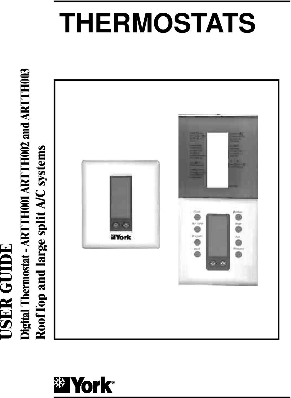
2 Table of Contents Page 1 - Specifications Product range...3 ARTTH001 (DSL-610)...3 ARTTH002 (DSL-700)...3 ARTTH003 (DSL-600) Technical data Power failures Temperature accuracy Installation Introduction Dimensions Location Installation and wiring Fixing the thermostat and cover to the installed base Dip Switch settings for ARTTH002 and ARTTH Wiring Thermostat ARTTH001 terminals Thermostat ARTTH002 terminals Connections between thermostat and equipment terminals - ARTTH Connections between thermostat and equipment terminals - ARTTH Thermostat ARTTH003 terminals Connections between thermostat and equipment terminals - ARTTH User controls Mode Cooling Heating Fan DAY/NIGHT button Celsius / Fahrenheit changeover Outdoor (odt) button Limited override Clock terminals (option) Remote sensor (option) Installing a remote sensor (ARTTH002 and ARTTH003 only) Single sensor installation Multiple sensor installation Using a duct sensor Troubleshooting Installation wiring diagrams...9 2

3 1 - Specifications Product range ARTTH001 (DSL-610) This thermostat may be used with the following units: - SOH/SIH (with or without electrical heating) - RTH (with or without electrical heating) - SCOH/SIH (with or without electrical heating) ARTTH002 (DSL-700) This thermostat may be used with the following units: - D2IC A50 (with or without electrical heating) - B2IH A50 (with or without single stage electrical heating) - D2IG A50. ARTTH003 (DSL-600) This thermostat may be used with the following units : - SOH/SIH SCOH/SIH Power failures Your thermostat employs the latest developments in solid state electronic technology. One of the unique features of your thermostat is that there is no battery required to maintain your selected setpoints in the event of a power loss. The memory is unaffected by power failures of any duration. When power is restored, the thermostat will continue operating as if the power had never been off Technical data Description Rated voltage Rated A.C. current Rated D.C. current Control range Thermostat measurement range 0 at 48 C O.D.T. measurement range -48 at 48 C Note : This thermostat contains electronic circuitry replacing the conventional mechanical anticipator Temperature accuracy Values Vac, or DC 24V nominal Amps to 0.75 Amps continuous per output with surges to 3 Amp max 0 Amps to 0.75 Amps continuous per output with surges to 3 Amp max Heating: 5 to 30 C; 1 C steps Cooling: 16 to 40 C; 1 C steps Control accuracy ± 0,5 C at 20 C Minimum deadband Between heating and cooling: 1 C Full temperature accuracy will only be realised after the thermostat has been installed and powered for at least one hour. 2 - Installation Introduction These thermostats use an adaptive control routine, based on fuzzy logic, to determine the heating or cooling load of the controlled space. The routine calculates load by evaluating recent room conditions, and room reactions to heating and cooling. This load is used to determine the cycle rate of the equipment, giving optimal control of the space Dimensions Location Locate thermostats as follows: - On an inside wall, and approximately 1,5 m above the floor in a location with freely circulating air of an of average temperat u r e. - Away from direct sunlight or radiant heat, outside walls or behind doors, air discharge grills, stairwells, or outside doors - Away from steam or water pipes, warm air stacks, unheated/uncooled areas, or sources of electrical interference. Fig. 1 Fig. 2 - Separating the thermostat from the base 3
 - D2IG090 300 A50. ARTTH003 (DSL-600) This thermostat may be used with the following units : - SOH/SIH 150-240 - SCOH/SIH 150-240 1.")
4 2 - Installation (cont d) Installation and wiring To install the thermostat: 1. Lift the thermostat cover and insert a flat blade screwdriver or coin into the slot located in the bottom center of the thermostat case and twist 1/4 turn. Grasp the base from the bottom two corners and separate from the thermostat. (See figure 2). 2. Swing the thermostat out from the bottom, and lift up and off the base. Place the rectangular opening in the base over the equipment control wires protruding from the wall and, using the base as a template, mark the location of the two mounting holes. No leveling is required. 3. Use the supplied anchors and screws for mounting on drywall or plaster. Drill two 5 mm holes at the marked locations, and tap nylon anchors flush to the wall surface and fasten. (See figure 3). 4. Connect the wires from the existing system to the thermostat terminals according to Wiring Tables 2 and 3. Push extra wire back into the wall. Wires must be flush to the plastic base Fixing the thermostat and cover to the installed based Fig Position the thermostat inside the cover and attach on the hinsed tabs located at the top of the base. 2. Swing the thermostat and cover down, and press on the bottom centre edge until they snap in place. (See figure 4). Fig. 3 - Mounting the base Dip Switch settings These DIP switches are used on the models ARTTH002 and ARTTH003 only. Depending on model, there may be either 6 or 8 DIP switches. The table below shows the description of the functions. S w i t c h / J u m p e r s e l e c t i o n s 1 Heat/Cool: 4 or 2 min. minimum on and off 2 Keyboard unlocked/locked 3 Fan immediate with heat call; or with plenum switch 4 Single stage Multistage 5 LED1 icon off/on 6 LED2 icon off/on Description Allows selection of minimum on/off time for compressors on heating and cooling. Allows user to disable buttons to prevent tampering Allows selection of immediate fan function with heat/cool call or function upon activation of plenum switch Allows selection of multiple stage heating or cooling Optional selection: LCD icon comes on with LED1 (dirty filters) Optional selection: LCD icon comes on with LED2 (compressor fault) Factory setting Heat/Cool : 4 minutes (minimum on) Keyboard unlocked Fan with heat/cool call Single stage LED 1 icon off LED 2 icon off Heat/Cool: 2 minutes (minimum on) Keyboard locked Fan with plenum switch Multistage LED 1 icon (dirty filters) LED 2 icon (Compressor fault) 4

5 2 - Installation (cont d) S w i t c h / J u m p e r s e l e c t i o n s 1 Not used 2 Not used 3 Heat/Cool: 4 or 2 min. minimum on and off 4 Keyboard unlocked/locked 5 Compressor is not able to start immediately with a change to temps setpoint. 6 Single stage Multistage 7 LED1 icon off/on 8 LED2 icon off/on Not used Not used Description Allows selection of minimum on/off time for compressors on heating and cooling. Allows user to disable buttons to prevent tampering Compressor may start immediately with a change to temperature setpoint df f Allows selection of multiple stage heating or cooling Optional selection: LCD icon comes on with LED1 (dirty filters) Optional selection: LCD icon comes on with LED2 (compressor fault) Normal Not used Heat/Cool : 4 minutes (minimum on) Keyboard unlocked Economy Single stage LED 1 icon off LED 2 icon off Not used Not used Heat/Cool: 2 minutes (minimum on) Keyboard locked Comfort Multistage LED 1 icon (dirty filters) LED 2 icon (Compressors fault) 3 - Wiring Thermostat ARTTH001 terminals Thermostat ARTTH002 terminals Jumper between 24V and R must be installed. Jumper between 24V and R must be installed. 5

6 3 - Wiring (cont d) Connections between thermostat and equipment terminals - ARTTH001 Thermostat terminal Unit terminal Description W W1 Auxilary heat : Electric heaters Y Y1 Compressor: With a call for cooling or heating G G Energises the fan circuit R R 24 VAC live 24V 24V 24 VAC live B B 24 VAC common O O Energises 4-way valve in cooling mode Use only copper conductors only. Section > 1mm Connections between thermostat and equipment terminals - ARTTH002 Thermostat terminal Unit terminal Description Y 2 Y 2 Energises on a call for 2nd stage cool W1 W1 Energises on a call for 1st stage heat Y1 Y1 Energises on a call for 1 s t stage cool G G Energises the fan circuit R R Independent switching voltage 24V 24 VAC live 24V(C) B 24 VAC common W 2 W 2 Energises on a call for 2nd stage heat LED1 optional Dirty filters LED2 X Refrigerant circuit fault CLK1 - Use with external clock/timer for alternate setpoints CLK2 RS2 - Remote Sensor (option). RS1 RS+V Use only copper conductors only. Section > 1mm Thermostat ARTTH003 terminals Jumper must be installed Connections between thermostat and equipment terminals - ARTTH003 Thermostat terminal Unit terminal Description H P 2 / Y 2 Y 2 Energises compressor with call for 2nd stage heat or cool AUX/W1 W1 Auxiliary heat : Electric heaters HP1/Y1 Y1 Energises compressor with call for 1st stage heat or cool G G Energises the fan circuit R R 24 VAC live X/24V (C) X 24 VAC common 0 0 Energises reversing valve in cooling mode B B * Energises reversing valve in heating m o d e LED1 optional Dirty filters LED2 LED2* Refrigerant circuit fault CLK1 - Use with external clock/timer for alternate setpoints CLK2 RS2 - Remote Sensor (option). RS1 RS+V Use only copper conductors only. Section > 1mm 2. * Only used on RTH-B, SOH-B and SCOH-B with Rol-on board. 6

7 4 - User controls MODE Select the desired mode of operation by pressing the MODE button repeatedly: - Controls cooling system only (the word "COOL" is displayed for 5 seconds). - Controls heating system only (the word " HEAT" is displayed for 5 seconds). - Controls both heating and cooling systems (auto changeover) (the word " AUTO " is displayed for 5 seconds). OFF - Disables thermostat so equipment will not operate (the word " OFF " is displayed). Avoid using the OFF mode during extremely cold weather to prevent damage from freezing. - Flashing - indicates Cool ON - Flashing - indicates Heat ON E HT - Emergency heat COOL Select the temperature you want your equipment to maintain while in the cooling mode by momentarily pressing the o r button. The temperature setpoint is displayed for 5 seconds after releasing the button. HEAT Select the temperature you want your equipment to maintain while in the heating mode by pressing and holding the o r buttons. The temperature setpoint is displayed for 5 seconds after releasing the button. FAN The Fan will come on automatically when the system is operating, but there is no indication of this on the display. To select continuous Fan operation, press the FAN button and the display will show. This is recommended for electronic air cleaners or continuous ventilation requirements. Note : The thermostat never allows less than 1 C diff e r e n c e between the heating and cooling setpoints. AUTO Selecting this mode of operation will control both heating and cooling functions. The thermostat will automatically switch from one to the other as determined by the selected setpoints in heating and cooling. DAY/NIGHT BUTTON Only available with ARTTH002 (DSL-700) and ARTTH003 (DSL-600) When the thermostat is initially installed, the display will show the symbol for your day temperature. By pressing the DAY / NIGHT button or closing the CLK1 and CLK2 terminals on the back of the thermostat (installer connected) you may select an alternate or night temperature. (The thermostat will remember this setpoint). Simply press the Day / Night button to alternate between temperature settings. CELSIUS / FAHRENHEIT Simultaneously press and to switch between F and C temperature display. "Outdoor" BUTTON Only available with ARTTH002 (DSL700) and ARTTH003 (DSL- 600) When the outdoor temperature sensor option is connected to your thermostat, you can display the current outdoor temperature by pressing the outdoor button. If the option is not connected, the thermostat will display "--". LIMITED OVERRIDE Only available with ARTTH002 (DSL700) and ARTTH003 (DSL- 600) When the keyboard is locked ( switch #2 "ON"), the user may override the temperature setpoint for 1 hour by pressing either the o r button. The range of temperature override is +/- 3 C from the programmed daytime setpoint. CLOCK TERMINALS (OPTION) CLK1 - CLK2 Only available with ARTTH002 (DSL700) and ARTTH003 (DSL- 600) Your thermostat is equipped with Remote Clock Terminals. By connecting a remote clock/ timer. The thermostat can be alternated between the Day/Night setpoints automatically. REMOTE SENSOR (OPTION) RS1 - RS2 - RS+V Only available with ARTTH002 (DSL700) and ARTTH003 (DSL- 600) These thermostats are designed to accept the Electronic Remote Sensor which will allow you to locate your thermostat in an area away from view. 7

8 5 - Installing a remote sensor I N S TALLING an ALSRS001S REMOTE Sensor, ALSDS001 duct sesor for ARTTH002 (DSL-700) and ARTTH003 (DSL-600) only. Introduction : The indoor sensor is designed to sense the air temperature at a remote location and send this information by digital communications to the thermostat. Any number of sensors up to six can be connected together to provide temperature averaging. The sensor can also be modified for use with a duct sensor. Single Sensor Installation : 1 - Install the ARTTH002 (DSL-700) or ARTTH003 (DSL-600) thermostat. Check that the thermostat is operating. (Display shows the correct temperature.) CAUTION : Remove the thermostat from the subbase while wiring the sensor to avoid damage from live wires. This is important. 2 - Install non-shielded 3 conductor wire from the thermostat to the remote sensor location. Maximum distance is (90m). 3 - Open the sensor case by depressing the button on the bottom edge of the case until the latch releases. Remove the cover by pulling it out and up at the bottom. 4 - Remove the board from the subbase by pulling back the latch that holds it at the center bottom. 5 - Use the sensorsubbase as a template to mark the mounting hole locations on the wall. Drill size for the wall anchors is 6 mm. Mount the subbase over the wires coming out of the wall using the two screws and anchors provided. The angled corner on the subbase should be in the bottom right. 6 - Snap the board back into the subbase. Check to be sure that the latch holds the board properly. Check that the thermistor (sensor element) is positioned under the holes in the cover but not touching the cover or subbase. 7 - Strip 6 mm of insulation from the three wires at the Remote Sensor. Install the wires in the terminals labelled RS2, RS+V and RS1. Push any extra wire back into the wall cavity. Seal the hole in the wall around the cable to eliminate any draft that might affect the sensor. Refer to Figure 1.) 8 - Note the wire colour going to each terminal. The order of the wires on the thermostat is not the same as the sensor. 9 - Connect the wires on the thermostat subbase to the terminals labelled RS2, RS1 and RS+V. Make sure that each terminal on the sensor is wired to the terminal with the same name on the thermostat Mount the thermostat on the subbase and check to be sure that it is showing the temperature Re-install the cover on the remote sensor by hooking it on the top and snapping the bottom into place. Using Multiple Sensors for Temperature Averaging : Any number from two to six sensors may be connected together to provide temperature averaging in a large area or several zones being controlled by the same system. Maximum distance between any 2 sensors is 300 ft. (90m). 1 - Wire the first sensor using the single sensor instructions. 2 - CAUTION : Make sure that there is no power to the sensors by removing the thermostat from the subbase. 3 - Connect wires to each additional sensor in the following manner. An outdoor sensor can also be connected in an location in the chain. (Refer to Figure 2 also.) Thermo- Sensor Sensor Sensor Other stat sensor RS+V RS+V RS+V RS+V RS2 RS2 RS2 RS2 RS1 RS1 RS1 RS1 AVG AVG AVG 4 - Replace the thermostat on the subbase. Check for proper operation of each sensor by connecting a jumper between terminals 1 and 2. This shorts out the thermistor. The displayed temperature will go up several degrees if the sensor is properly installed. Repeat for each sensor. Using a Duct Sensor : The ALSRS001S sensor and ARTTH002/003 thermostats are designed to sense air temperature in a room. The fast moving air in a duct has small but rapid changes in temperature. This will affect the control algorithm of the thermostat. For better control, it is recommended that the air temperature is sensed in the room. 1 - Install the indoor sensor using the Single Sensor instructions. 2 - Clip the thermistor from the Indoor sensor with wire cutters as shown in Figure Install the duct sensor in the retum air duct according to the instructions supplied with it. Connect the two wires from the duct sensor to terminals 1 and 2 of the indoor sensor. If shielded cable was required because of a long distance to the sensor box, connect the shield to terminal 2 also. Troubleshooting : Thermostat has no display : Check wiring between therrnostat and sensor. Incorrect wiring can damage the thermostat, transformer or blow a fuse. Check 24VAC supply. Thermostat reads "AC" : 24VAC power is disconnected. Not sure if display Is showing local or remob temperature : Breathe on the wall near the bottom left corner of the thermostat. Temperature will go up for a few seconds if sensing locally. Thermostat displays very hlgh temperature : Wires on sensor element are shorted together. Separate them. Thermostat displays very low temperature : Check wiring of probe or duct sensor. Sensor element is not connected to board or is broken. 8
 or ARTTH003 (DSL-600) thermostat. Check that the thermostat is operating. (Display shows the correct temperature.")
9 5 - Installing a remote sensor (cont d) SINGLE SENSOR ARTTH002 (DSL700) or ARTTH003 (DSL600) ALSRS001S (SL-IDS) PLEASE NOTE : Max cable length between any 2 units : 300ft. (90m) Max. number of indoor sensors in daisy chain : 6 Max. number of duct sensors in daisy chain : 1 FIGURE 1 ARTTH002 (DSL700) or ARTTH003 (DSL600) MULTIPLE SENSOR (TEMPERATURE AVERAGING) ALSRS001S ALSRS001S To other sensors (Max 6 total) FIGURE 2 INSTALLING AN ALSD5001S DUCT SENSOR ARTTH002 (DSL 700) ARTTH003 (DSL 600) ALSRS001S RETURN AIR DUCT Clip out Thermistor Connect the shield to terminal 2 FIGURE 3 ALSDS001 (RDS10K) DUCT SENSOR 9
 FIGURE 2 INSTALLING AN ALSD5001S DUCT SENSOR ARTTH002 (DSL 700) ARTTH003 (DSL 600) ALSRS001S RETURN AIR DUCT Clip out")
10 10

11

12 Europe E - UG - R0001 Manufacturer reserves the right to change specifications without prior notice.

Install Guide CT100. Caution. Caution ENGLISH. disconnect the power supply before beginning work.
 Install Guide CT100 PG 1 Caution top cover Your thermostat is a precise instrument, handle it with care. Turn off electricity to the system before installing or servicing thermostat or any part of the
HEAT PUMP PROGRAMMABLE THERMOSTAT
 HEAT PUMP PROGRAMMABLE THERMOSTAT SA PM 3 COOL TEMP Form 44014-01 r010408 Model 43168 Owners Manual 1 Congratulations! Heat Pump Programmable Thermostat Model 43168 THERMOSTAT CONTROLS Switches & Buttons...15
USER MANUAL WARNING! CONTENTS MODEL 1 SPECIFICATIONS READ ALL INSTRUCTIONS BEFORE PROCEEDING. Non-Programmable Single Stage Heat/Cool Thermostat
 Builder MODEL 1010 Series Non-Programmable Single Stage Heat/Cool Thermostat USER MANUAL Compatible with low voltage single stage gas, oil or electric heating or cooling systems, including single stage
DUAL SENSING DIGITAL THERMOSTAT PRODUCT INSTRUCTIONS. Construction Automotive Industry
 DUAL SENSING DIGITAL THERMOSTAT PRODUCT INSTRUCTIONS www.rehau.com Construction Automotive Industry SCOPE This guide gives instruction regarding REHAU Programmable Digital Thermostat installation and operation.
its ELECTRIC POSITION for electric heat, or set the units fan control appropriately to ELECTRIC or another appropriate setting.
 Troubleshooting Poor Temperature Regulation This page lists problems that may affect the temperature performance of your LUX thermostat with suggested resolutions. For more detailed information please
Install Guide CT101. Caution. Caution
 Install Guide CT101 PG 1 Caution top cover Your thermostat is a precise instrument, handle it with care. Turn off electricity to the system before installing or servicing thermostat or any part of the
TABLE 1: Wiring Terminals. Connect to... 1C 1H 2C 2H 1H1C 2H1C 2H2C 3H2C
 Installation TURN OFF POWER TO THE SYSTEM AT THE MAIN POWER PANEL TO AVOID ELECTRICAL SHOCK. Installation should be carried out by an electrician or a qualified technician. 1.1 Find a Location for the
Installation Guide. VisionPRO. TH8000 Series. Need Help? This manual covers the following models. System Types
 Installation Guide VisionPRO TH8000 Series Touch-screen Programmable Thermostat This manual covers the following models TH8110U: For 1 Heat/1 Cool systems TH8320U: For up to 3 Heat/2 Cool systems TH8321U:
T6861 Series Large LCD Digital Thermostat 110/220 VAC 2-pipe/4-pipe fan coil control
 T Series arge CD Digital Thermostat 0/0 VAC -pipe/-pipe fan coil control Data sheet Application T digital thermostats are designed for application of -speed fan and s in fan coil system. Including: -pipe
Install Guide 3M-50. Caution. Caution
 PG 1 Install Guide 3M-50 aution Your thermostat is a precise instrument, handle it with care. Turn off electricity to the HVA system before installing or servicing thermostat or any part of the system.
HEAT HEAT COOL HEAT PUMP COOL
 OWNER S MANUAL RESIDENTIAL THERMOSTAT P/N P374-1800 HEAT COOL HEAT PUMP Su AUTO 0I20: Pm 74 COOL HEAT 27 7-DAY MABLE DIGITAL THERMOSTAT 3 Configurable Outputs Accepts Optional Humidity Module: Control
ETC TWO STAGE ELECTRONIC TEMPERATURE CONTROL
 RANCO INSTALLATION INSTRUCTIONS ETC TWO STAGE ELECTRONIC TEMPERATURE CONTROL Relay Electrical Ratings PRODUCT DESCRIPTION The Ranco ETC is a microprocessor-based family of electronic temperature controls,
ELECTRIC POSITION for electric heat, then confirm with Fan Test below.
 Troubleshooting Poor Temperature Regulation This page lists problems that may affect the temperature performance of your LUX thermostat with suggested resolutions. For more detailed information please
Installation Guide. LR-HWLV-HVAC TouchPRO Wireless. System Types
 Installation Guide LR-HWLV-HVAC TouchPRO Wireless Touchscreen Thermostat System Types Gas, oil, or electric heat with air conditioning Warm air, hot water, high efficiency furnaces, heat pumps, steam,
T-100-R Installation Guide
 T-100-R Installation Guide Table of Contents Page 2 Overview T-100-R Z-Wave Thermostat 3-4 Installation HVAC System Setup 6 Installer Settings Menu Items 7-9 Installer Settings Summary 10-11 Wiring Standard
T7560A,B,C Digital Wall Module
 T7560A,B,C Digital Wall Module HONEYWELL EXCEL 5000 OPEN SYSTEM BEFORE INSTALLATION All wiring must comply with local electrical codes and ordinances or as specified on installation wiring diagrams. Digital
Installation Guide. Programmable Thermostat TH6220D
 Installation Guide Programmable Thermostat TH6220D Product Application This thermostat provides electronic control of 24 VAC single-stage and multi-stage heating and cooling systems, or 750 mv heating
1F82-0261 5/1/1 Day Programmable. 1F82-0261 Thermostat Thermostat Configuration Options Heat Pump. Maximum Stages Heat/Cool 2/1
 Blue 2 Heat Pump Thermostat Heat Pump Installation and Operating Instructions Save these instructions for future use! FAILURE TO READ AND FOLLOW ALL INSTRUCTIONS CAREFULLY BEFORE INSTALLING OR OPERATING
Mode Switch. Fan Switch Menu button Program button
 Operation 3M-30 Day Time of day Target Temperature Time Slot Touch Screen Current Room Temperature Thermostat Mode Statement of use: The 3M-30 can be used with millivolt, 24VAC, single and 2 stage conventional
How To Control A Thermostat
 CONTENTS Installation Instructions for Heating & Air Conditioning 1F72 5/2 Day Programmable Heat Pump Thermostat Preparations... 1 Thermostat Details... 1 Removing Old Thermostat... 1-2 Mounting and Wiring...
HVAC-32A. Operation Manual. Specifications. Digital Multistage Air Conditioning Controller with inbuilt Outside Air Economy function
 Specifications Supply Voltage 240VAC @ 0.07Amps or 24VAC @ 0.380Amps Relays 240V @ 12A max (resistive) / Comp1,2,3, Aux Ht, Rv O/B) Fuses (Equipment) 15 Amps Maximum 3AG Control Range Minus 10 to 50C Control
Installation Questions
 Installation Questions How do I determine what type of heat I have? There may be several ways to determine what type of heat you have. First, if you can access the unit that is responsible for creating
Drayton Digistat +2RF/+3RF
 /+3RF Programmable Room Thermostat Wireless Model: RF700/22090 Model: RF701/22092 Power Supply: Battery - Thermostat Mains - Digistat SCR Invensys Controls Europe Customer Service Tel: 0845 130 5522 Customer
Programmable Thermostat MODEL 3312026.XXX With Dehumidify 3312024.XXX With Out Dehumidify
 Comfort Control Center 2 Thermostat Operating Instructions Programmable Thermostat MODEL 3312026.XXX With Dehumidify 3312024.XXX With Out Dehumidify TABLE OF CONTENTS About your new thermostat Features...2
Installation Instructions
 TP-PRH-A, TP-NRH-A Performance Series Edge Thermidistat Control Installation Instructions Programmable Control A07049 A07048 Non Programmable Control Designed and Assembled in the USA. NOTE: Read the entire
INSTALLATION INSTRUCTIONS MC95HAE-1 MASTER CONTROLLER
 INSTALLATION INSTRUCTIONS MC95HAE-1 MASTER CONTROLLER Bard Manufacturing Company, Inc. Bryan, Ohio 43506 Since 1914...Moving ahead just as planned. Manual : 2100-360B Supersedes: 2100-360A File: Volume
1F82-261 Programmable Electronic Digital Heat Pump Thermostat INSTALLATION AND OPERATION INSTRUCTIONS
 FAILURE TO READ AND FOLLOW ALL INSTRUCTIONS CAREFULLY BEFORE INSTALLING OR OPERATING THIS CONTROL COULD CAUSE PERSONAL INJURY AND/OR PROPERTY DAMAGE. DESCRIPTION ELECTRICAL DATA Electrical Rating: 20 to
QUICK INSTALLATION GUIDE
 QUICK INSTALLATION GUIDE Read Installer Notes before removing cover from Thermostat. 1F85RF-275 Wireless Remote Kit INSTALLER NOTES IMPORTANT Do not apply power to the thermostat or wireless sensor until
Alpha Climatic Programmable Modulating Boiler Energy Manager. Installation and User Instructions
 Alpha Climatic Programmable Modulating Boiler Energy Manager Part No 3.022144 (Hard Wired) Part No 3.022143 (Radio Frequency) Installation and User Instructions 1. Description The Alpha Climatic energy
Installation Instructions
 Installation Instructions Model TSTATG2111 Use with most systems: 2-Heat, 1-ool 1- Day Prog ram m ab l e Digital Thermostat u p t o 2 - H e a t & 1 - o o l ontrol up to 2 Heat & 1 ool Stages Backlit Display
SERVICE MANUAL FOR 6535 SERIES TWO TON HIGH EFFICIENCY PACKAGED HEAT PUMPS
 SERVICE MANUAL FOR 6535 SERIES TWO TON HIGH EFFICIENCY PACKAGED HEAT PUMPS TABLE OF CONTENTS 1. Warnings...2 2. Accessibility Of Appliance...3 3. Unit Dimensions And Specifications...3 4. Unit Specifications
FOXAIR 60/50 ALL MODELS
 FOXAIR 60/50 ALL MODELS OPERATION AND SERVICE MANUAL UNIT WEIGHT - ALL MODELS APPROX. 300 POUNDS FOXTRONICS, INC. 38 L x 28 W x 24 H Love Field-Dallas TX MADE IN THE USA 3448 West Mockingbird Lane Dallas,
CT3200 Programmable Thermostat
 CT3200 Programmable Thermostat Welcome to the world of comfort and energy savings with your new Honeywell Programmable Thermostat. Your new thermostat will automatically control the temperature in your
PSPA711a. LUXPRO PSPA711a INSTALLATION AND OPERATING INSTRUCTIONS. Mt. Laurel, New Jersey 08054, USA www.luxproproducts.com
 PSPA711a LUXPRO PSPA711a INSTALLATION AND OPERATING INSTRUCTIONS 52070 1 COMPATIBILITY...................................... 2 2 FEATURES............................................ 2 3 ELECTRICAL RATINGS................................
Single Zone LCD Thermostat Operating Instructions
 Fan Cool Furnace *Heat Pump or Heat Strip On/Off F Single Zone LCD Thermostat Operating Instructions MODEL 3313192.XXX Cool/Furnace 3313193.XXX Cool/Furnace/Heat Pump 3313194.XXX Cool/Furnace/Heat Strip
PRODUCT PRODUCT CODE TECHNICAL INSTRUCTIONS PAGE
 Table of Contents PRODUCT PRODUCT CODE TECHNICAL INSTRUCTIONS PAGE # Electric Room Comfort Controller NEW! RDY2000 Room Comfort Controller RDY 129-905 D-3 Electric for Specialized Applications Surface
Service manual. Website: www.andico.com.au CAUTION - BEFORE SERVICING THE UNIT, READ THE SAFETY - PRECAUTIONS IN THIS MANUAL.
 Website: www.andico.com.au Service manual CAUTION - BEFORE SERVICING THE UNIT, READ THE SAFETY - PRECAUTIONS IN THIS MANUAL. - ONLY FOR AUTHORISED SERVICE PERSONNEL. MODELS: MPK1-09CR-QB8 MPK1-12ER-QB6
Portable Air Conditioner
 Portable Air Conditioner Owner's Manual Model:3 in 1 12,000 Btu/h Series 3 Please read this owner s manual carefully before operation and retain it for future reference. CONTENTS 1. SUMMARY...1 2. PORTABLE
Roof Top Air Conditioner INSTALLATION AND OPERATING INSTRUCTIONS
 Roof Top Air Conditioner INSTALLATION AND OPERATING INSTRUCTIONS Ducted System RECORD THIS UNIT INFORMATION FOR FUTURE REFERENCE: Model Number: Serial Number: Date Purchased: This manual must be read and
COMPUTHERM Q7 Programmable, digital room thermostat. Operating Instructions
 COMPUTHERM Q7 Programmable, digital room thermostat Operating Instructions GENERAL DESCRIPTION OF THE THERMOSTAT The COMPUTHERM Q7 type switched-mode room thermostat is suitable to regulate the overwhelming
Programmable Room Thermostat 7 Day (5-2 Day) Models: 22083 / 22087 Power Supply: Battery / Mains
 Models: 22083 / 22087 Power Supply: Battery / Mains") Drayton Programmable Room Thermostat 7 Day (5-2 Day) Models: 22083 / 22087 Power Supply: Battery / Mains Invensys Controls Europe Technical Helpline: +44 (0) 845 130 7722 www.draytoncontrols.co.uk Installation
Drayton Programmable Room Thermostat 7 Day (5-2 Day) Models: 22083 / 22087 Power Supply: Battery / Mains Invensys Controls Europe Technical Helpline: +44 (0) 845 130 7722 www.draytoncontrols.co.uk Installation
INSTALLER S & OWNER S MANUAL
 INSTALLER S & OWNER S MANUAL HVAC INSTALLER: PLEASE LEAVE MANUAL FOR HOMEOWNER DEH 3000 DEH 3000 Part No. 4028539 Dehumidifier & Ventilation System Controller P.O. Box 8680 Madison, WI 53708 TOLL-FREE
INSTALLATION INSTRUCTIONS AIRCOMMAND IBIS ROOFTOP AIRCONDITIONER
 \ INSTALLATION INSTRUCTIONS AIRCOMMAND IBIS ROOFTOP AIRCONDITIONER Suitability: The IBIS caravan rooftop aircondioner is suitable for installation on caravans and motorhomes provided the roof structure
1-877-654-9394. UP400 Programmable Thermostat Installation Instructions & User Guide. For Installation Help. White-Rodgers.com
 UP400 Programmable Thermostat Installation Instructions & User Guide For Installation Help 1-877-654-9394 White-Rodgers.com 2011 Printed in China White-Rodgers 8100 West Florissant Avenue St. Louis, MO
To suit Daikin FDY "F" Series and FD "F" Series. (and other models incorporating BRC1B62/52 Remote Controller)
") OPERATION MANUAL Split System Ducted Air Conditioner To suit Daikin FDY "F" Series and FD "F" Series AIR CONDITIONER A hr o C (and other models incorporating BRC1B62/52 Remote Controller) Dear Owner, Thank
OPERATION MANUAL Split System Ducted Air Conditioner To suit Daikin FDY "F" Series and FD "F" Series AIR CONDITIONER A hr o C (and other models incorporating BRC1B62/52 Remote Controller) Dear Owner, Thank
R22. K Control. Indoor Unit. Nomenclature. Compatibility PL H 3 G K H B. Unit style Heat Pump Horse Power
 R22. K Control. Indoor Unit. Nomenclature. PL H 3 G K H B Compatibility Unit style Heat Pump Horse Power Control Boost Heaters R22. K Control. Outdoor Unit. Nomenclature. PU H 3 Y K A Compatibility Outdoor
SERVICE MANUAL 12VDC WALL THERMOSTAT AIR CONDITIONING SYSTEMS ROOFTOP UNITS ONLY
 SERVICE MANUAL 12VDC WALL THERMOSTAT AIR CONDITIONING SYSTEMS ROOFTOP UNITS ONLY! WARNING - SHOCK HAZARD! TO PREVENT THE POSSIBILITY OF SEVERE PERSONAL INJURY, DEATH, OR EQUIPMENT DAMAGE DUE TO ELECTRICAL
Sensi TM. Wi-Fi Programmable Thermostat MANUAL OPERATION. Version: March 2016 2016 Emerson Electric Co. All rights reserved.
 Sensi TM Wi-Fi Programmable Thermostat MANUAL OPERATION Version: March 2016 2016 Emerson Electric Co. All rights reserved. Contents MANUAL OPERATION GUIDE Buttons and Icons 3 Basic Functionality 4 Manual
Important Safeguards
 Table of Contents Important Safeguards...2 Product Layout...3 Preparing for Use...4 Air-conditioning without installation...4 Air-conditioning with installation...5 Control Panel...6 Operating from the
HERZ-Thermal Actuators
 HERZ-Thermal Actuators Data Sheet 7708-7990, Issue 1011 Dimensions in mm 1 7710 00 1 7710 01 1 7711 18 1 7710 80 1 7710 81 1 7711 80 1 7711 81 1 7990 00 1 7980 00 1 7708 11 1 7708 10 1 7708 23 1 7709 01
Installing the Tracer ZN517 Unitary Controller Ordering number: 4950 0496, 4950 0596
 Installing the Tracer ZN517 Unitary Controller Ordering number: 4950 0496, 4950 0596 Product overview The Tracer ZN517 controller is a field-installed, application-specific controller that provides directdigital
Operation Guide 3M-22
 Operation Guide 3M-22 TEMP UP Target Temp Time Reset TEMP DOWN Control Panel Heat/Cool Mode Switch Fan Switch Battery Compartment Statement of use: The 3M-22 can be used with - millivolt, 24VAC single
Failure code manual. content
 Failure code manual content 一 wall split AC series 2 二 floor standing AC series. 4 三 portable AC series.. 5 四 dehumidifer 6 五 DC inverter single split series...7 六 DC inverter multi-split series 10 1 一
Si10-417_C. Pocket Manual. Service Diagnosis SPLIT & MULTI
 Pocket Manual Service Diagnosis SPLIT & MULTI Service Diagnosis SPLIT & MULTI 1. Troubleshooting with LED...5 1.1 Indoor Unit... 5 1.2 Outdoor Unit... 10 2. Troubleshooting by Symptoms...11 2.1 Air conditioner
Installation Instructions
 TP --- PAC, TP --- PHP TP --- NAC, TP --- NHP Performance Series AC / HP Thermostat Installation Instructions A07049 Programmable Control A07048 Non-Programmable Control Designed and Assembled in the U.S.A.
SINCE 1 8 8 6 AUTO SAVER 550. OwnerÕs Manual Model 44550
 SINCE 1 8 8 6 AUTO SAVER 550 5: 7 2 2 3 2 OwnerÕs Manual Model 44550 Ask Your Local Retailer for Other Quality Products from unter Fans Air Purifiers umidifiers To locate your nearest unter Dealer, call
WHITE-RODGERS COMFORT-SET 90 SERIES
 INSTALLATI DESCRIPTI WHITE-RODGERS COMFORT-SET 90 SERIES MULTI-STAGE INSTALLATI/CFIGURATI This White-Rodgers Automatic Setback Digital Thermostat uses microcomputer technology to provide precise time and
SERVICE INSTRUCTION R410A. WALL MOUNTEDtype INVERTER SPLIT TYPE ROOM AIR CONDITIONER. Models Indoor unit Outdoor unit
 SERVICE INSTRUCTION SPLIT TYPE ROOM AIR CONDITIONER WALL MOUNTEDtype INVERTER Models Indoor unit Outdoor unit ASYG07LECA ASYG09LECA ASYG12LECA ASYG14LECA AOYG07LEC AOYG09LEC AOYG12LEC AOYG14LEC R410A CONTENTS
Inwall Room Temperature Unit
 Inwall Room Temperature Unit TM11B01KNX TM11B11KNX TM11B21KNX Product Handbook Product: Inwall Room Temperature Unit Order Code: TM11B01KNX TM11B11KNX TM11B21KNX Application Program ETS: TM11B_1KNX Inwall
Wireless 7 Day Programmable Room Thermostat
 Wireless 7 Day Programmable Room Thermostat Cat. No. TRT037 Transmitter Receiver Operating & Installation Instructions What is a programmable room thermostat? an explanation for householders A programmable
OWNER S MANUAL VMH 09/12/18/27/36 InverterFlex
 OWNER S MANUAL VMH 09/12/18/27/36 InverterFlex Version C Single, Dual, Tri or Quad Zone Ductless Mini-Split System Heat Controller, Inc. 1900 Wellworth Ave. Jackson, MI 49203 (517)787-2100 www.heatcontroller.com
AIR CONDITIONER & HEAT PUMP SERVICE MANUAL
 AIR CONDITIONER & HEAT PUMP SERVICE MANUAL AL This Service Manual is the result of the dedication of The Dometic Corporation and its engineers to providing service people the necessary instructions for
EPSOLAR LS0512R / LS0524R. Solar Light Controller INSTRUCTION MANUAL. Please read this manual carefully before using the product!
 EPSOLAR LS0512R / LS0524R Solar Light Controller INSTRUCTION MANUAL Please read this manual carefully before using the product! LandStar LS0512R / LS0524R Solar Light Controller Nominal system voltage
UB1 AIR CONDITIONING UNIT INSTALLATION INSTRUCTIONS
 UB1 AIR CONDITIONING UNIT INSTALLATION INSTRUCTIONS INSTALLATION INSTRUCTIONS: Carefully read these instructions before installing your new air-conditioner. AUSTRALIAN AUTOMOTIVE AIR AL00500054E 1 Table
EK908FHL - Thermostat for floor heating
 EK908FHL - Thermostat for floor heating EK908FHL is a programmable thermostat designed for floor warming application or helping to limit floor temperature. This thermostat can be used for hot water radiant
SERVICE MANUAL. Room Air Conditioner Multi Split Wall-Mounted Type Indoor. FSAI-Pro-91AE2 FSAI-Pro-121AE2 FSAIF-Pro-181AE2
 SERVICE MANUAL Room Air Conditioner Multi Split Wall-Mounted Type Indoor FSAI-Pro-91AE2 FSAI-Pro-121AE2 FSAIF-Pro-181AE2 NOTE: Before servicing the unit, please read this at first. Always contact with
User Manual THR840DUK Digital Thermostat
 User Manual THR840DUK Digital Thermostat 50051982-001 Rev. A WARNING: This product must be correctly installed and configured to work properly (see pages 12-24). If you are not experienced in wiring electrical
SECTION 15750 PACKAGED ROOFTOP AIR CONDITIONING UNITS
 SECTION 15750 PART 1 - GENERAL 1.01 DESCRIPTION A. Section includes requirements for roof mounted, self-contained units, with electric cooling, and electric or reverse refrigeration cycle (heat pump) heating
USER INSTRUCTIONS FOR GET PORTABLE 12k BTU AIR CONDITIONER MODEL No. GPACU12HR
 USER INSTRUCTIONS FOR GET PORTABLE 12k BTU AIR CONDITIONER MODEL No. GPACU12HR CONTENTS Introduction Safety Notes Identification of parts Installation instructions Operation instructions Maintenance Troubleshooting
Operator: Save these instructions for future use!
 WHITE-RDERS 1F58-72 Low Voltage Multi-Stage Heat PumpThermostat INSTALLATIN INSTRUCTINS perator: Save these instructions for future use FAILURE T READ AND FLLW ALL INSTRUCTINS CAREFULLY EFRE INSTALLIN
TECHNICAL DATA & SERVICE MANUAL SPLIT SYSTEM AIR CONDITIONER INDOOR UNIT: AW52AL AW64AL AW52AL 387030095 AW64AL 0.8180.463.0 07/05
 TECHNICAL DATA & SERVICE MANUAL INDOOR UNIT: AW52AL AW64AL SPLIT SYSTEM AIR CONDITIONER Model No. Product Code No. AW52AL 387030095 AW64AL 387030096 0.8180.463.0 07/05 IMPORTANT! Please read before installation
AIR CONDITIONER INSTALLATION MANUAL
 INSTALLATION MANUAL AIR CONDITIONER Please read this installation manual completely before installing the product. Installation work must be performed in accordance with the national wiring standards by
HP 5 Microprocessor Control for Mammoth Water Source Heat Pumps
 HP 5 Microprocessor Control for Mammoth Water Source Heat Pumps Operation and Maintenance Manual Model: 71028004 Applies to: Single Circuit Water-to-Water Twin Circuit Units Without DDC Controls MAMM WHSP
IMPORTANT INSTRUCTIONS & OPERATING MANUAL. Houston 50 Inch Electric Wall Mounted Fireplace Black / White
 IMPORTANT INSTRUCTIONS & OPERATING MANUAL Houston 50 Inch Electric Wall Mounted Fireplace Black / White Model Number:MFE5050BK Model Number:MFE5050WH Read these instructions carefully before attempting
MOUNTING AND OPERATING INSTRUCTIONS
 MOUNTING AND OPERATING INSTRUCTIONS CF 51/55 1. Delivery CF 51/55-1 calculator with battery (optionally with mains power supply) - 1 wall mounting bracket - package with material for sealing, screws, wall
ELECTRONIC THERMOSTAT AND THERMOMETER With SPEED CONTROL
 148 OLD CONCORD TURNPIKE, BARRINGTON NH 03825 USA TEL (603) 868-5720 FAX (603) 868-1040 1-800-435-6708 E-Mail:[email protected] www.seafrost.com ELECTRONIC THERMOSTAT AND THERMOMETER With SPEED CONTROL
DUCT TYPE AIR CONDITIONER
 OPERATING MANUAL OPERATING MANUAL BEDIENUNGSANLEITUNG MODE D EMPLOI MANUAL DE FUNCIONAMIENTO MANUALE DI ISTRUZIONI ΕΓΧΕΙΡΙ ΙΟ ΛΕΙΤΟΥΡΓΙΑΣ MANUAL DE INSTRUÇÕES AIR CONDITIONER DUCT TYPE English Deutsch
YOUR THERMOSTAT REPLACES Assemble tools required as shown below. HAND OR POWER DRILL WITH 3/16 INCH DRILL BIT, IF NEEDED
 1F85-275 Heating & Air Conditioning 5-1-1 Programmable/Non-programmable, Auto Changeover, Multi-Stage/Heat Pump Thermostat INSTALLATION INSTRUCTIONS Operator tor: Save these instructions for future use!
ComfortLink II Installation Guide. 3 Zone Panel (optional) 4 Zone Sensor with Display (optional) 5 Zone Sensor (optional) 6 Zone Dampers (optional)
 4 Zone Sensor with Display (optional) 5 Zone Sensor (optional) 6 Zone Dampers (optional)") 18-HD64D1-3 ComfortLink II Installation Guide Other Installation Guides may be necessary, based on system configuration. A complete list of other optional components is shown below. 1 Control 2 Relay Panel
18-HD64D1-3 ComfortLink II Installation Guide Other Installation Guides may be necessary, based on system configuration. A complete list of other optional components is shown below. 1 Control 2 Relay Panel
LUCCI AIRFUSION QUEST II CEILING FAN
 LUCCI AIRFUSION QUEST II CEILING FAN WITH IR REMOTE INSTALLATION OPERATION MAINTENANCE WARRANTY INFORMATION CAUTION READ INSTRUCTIONS CAREFULLY FOR SAFE INSTALLATION AND FAN OPERATION. V1.0 QUEST II IR
Please read this owner s Manual carefully before operating the unit. - Cooling - Heating - Dehumidifying - Fan
 Please read this owner s Manual carefully before operating the unit. - Cooling - Heating - Dehumidifying - Fan TABLE OF CONTENTS INTRODUCTION 2 IMPORTANT SAFEGUARDS...2 PACKAGE CONTAINS..2 NAMES OF PARTS.3
HP Laser Jet 4200/4240/4250/4300/4350 Swing Plate
 HP Laser Jet 4200/4240/4250/4300/4350 Swing Plate 1 Swing Plate Assembly-RM1-0043 1 Swing Plate Kit-5851-2766 (RM1-0043 plus RM1-1091 gear) CAUTION: Fuser may be hot. Turn off printer, unplug it and allow
HMI display Installation Guide
 HMI display Installation Guide Product Description Specifications Important Information o Package Contents o Related Documents o Accessories Cautions and Warnings Mounting and Dimensions o BAC-DIS-ENC
SERVICE INSTRUCTION R410A. SPLIT TYPE ROOM AIR CONDITIONER Universal Floor / Ceiling Duct / Cassette Wall Mounted / Floor type INVERTER MULTI
 SERVICE INSTRUCTION SPLIT TYPE ROOM AIR CONDITIONER Universal Floor / Ceiling Duct / Cassette Wall Mounted / Floor type INVERTER MULTI R410A Models Indoor unit Outdoor unit AB*14LBAJ AB*18LBAJ AB*F14LAT
Roof Top Unit. Description Model Type Use With Air Distribution Box. Heat Pump B3200 3242 3311669.018 Integral Mechanical
 RECORD THIS UNIT INFORMATION FOR FUTURE REFERENCE: Type Number Product Number Serial Number ADB Number ADB Serial Number Date Purchased Roof Top Unit Description Model Type Use With Air Distribution Box
PK5500 v1.1 Installation Instructions
 PK5500 v1.1 Installation Instructions 1 2 3 4 5 6 7 8 9 * 0 # WARNING: Please refer to the System Installation Manual for information on limitations regarding product use and function and information on
T841A Heating-Cooling Heat Pump Thermostat
 T84A Heating-Cooling Heat Pump Thermostat APPLICATIN The T84A Heating-Cooling TADELINE Thermostat provides 4 Vac control of two-stage heating and onestage cooling in heat pump systems, using manual changeover.
Portable Air Conditioner. OWNER S MANUAL Read these instructions before use. Model: MM14CCS. Voltage rating: 115V~60Hz Power rating : 1400W
 Portable Air Conditioner OWNER S MANUAL Read these instructions before use Model: MM14CCS Customer Support : 1-800-474-2147 Voltage rating: 115V~60Hz Power rating : 1400W For product inquiries or support
SERVICE INSTRUCTION R410A. WALL MOUNTEDtype SPLIT TYPE ROOM AIR CONDITIONER INVERTER. Models Indoor unit Outdoor unit AOU 9RLFW AOU12RLFW AOU15RLS
 SERVICE INSTRUCTION SPLIT TYPE ROOM AIR CONDITIONER WALL MOUNTEDtype INVERTER Models Indoor unit Outdoor unit ASU 9RLF ASURLF ASU5RLS AOU 9RLFW AOURLFW AOU5RLS R40A CONTENTS. DESCRIPTION OF EACH CONTROL
SC 2201. Installation, Operation & Application Guide
 SC 2201 Manual Changeover Non-Programmable Hardwired Non-Programmable Electronic Thermostat For use with Heat Pumps Up to 2-Stage Heat, 2-Stage Cool 30-Minute Power Loss Memory etention For use with 24
Vertical Display and Storage B1350-2. SKOPE Gen2: Three Door Chiller
 Vertical Display and Storage User Manual MAN1227 Rev. 3.0 March 2008 edition CONTACT ADDRESSES Designed and Manufactured by New Zealand SKOPE INDUSTRIES LIMITED PO Box 1091, Christchurch New Zealand Freephone:
TR21, TR22, TR23, and TR24 Wall Modules
 TR21, TR22, TR23, and TR24 Wall Modules FEATURES INSTALLATI INSTRUCTIS The TR21, TR22, TR23, and TR24 family of wall modules include: Models with setpoint adjustment. Models with humidity output. Models
Instruction manual for Firstline FCS12000CH
 Instruction manual for Firstline FCS12000CH Contents Introduction... 2 Safety Awareness... 3 Safety Awareness... 4 Name of Parts... 5 Name of Parts... 6 Remote Controller Preparation... 7 Operation of
Contractors Guide Central Inverter System Installation
 Contractors Guide Central Inverter System Installation Step By Step Procedures 2,200 Watt/VA 6 Step Installation 1. Mount Bottom Cabinet 2. Mount Top Cabinet 3. Install Batteries 4. Install Conduit 5.
WALL MOUNTED SPLIT TYPE AIR CONDITIONER
 WALL MOUNTED SPLIT TYPE AIR CONDITIONER MANUAL 8 OM-G12-ACSON CONTENTS - Operating Guide page 1 - G12 Remote Controller Indication page 2 - Indicator Lights page 4 - Installation of Aroma page 5 - Auto
USER S MANUAL. Duct Type Series. Free Joint Multi Air Conditioner (Cooling and Heating) FUEA Series E S F I P D G DB98-29565A(1) ENGLISH ESPAÑOL
 FUEA Series E S F I P D G DB98-29565A(1) ENGLISH ESPAÑOL") USER S MANUAL Duct Type Series MH MH FEEA Series FUEA Series ENGLISH ESPAÑOL PORTUGUÊS E HNIKA DEUTSCH ITALIANO FRANÇAIS Free Joint Multi Air Conditioner (Cooling and Heating) E S F I P D G DB98-29565A(1)
USER S MANUAL Duct Type Series MH MH FEEA Series FUEA Series ENGLISH ESPAÑOL PORTUGUÊS E HNIKA DEUTSCH ITALIANO FRANÇAIS Free Joint Multi Air Conditioner (Cooling and Heating) E S F I P D G DB98-29565A(1)
PANASONIC TROUBLE SHOOTING GUIDE
 A General Guide To Room Style Products Pipework Pipe sizes and lengths should be as the relevant Technical Guide Both lines should be insulated No line accessories or oil traps should be fitted In cooling
543-0032-00, 943-0032-00. User s Manual
 543-0032-00, 943-0032-00 User s Manual 1 Comfort Alert Diagnostics Faster Service And Improved Accuracy The Comfort Alert diagnostics module is a breakthrough innovation for troubleshooting heat pump and
PRODUCT: WASHER / WASHER-DRYER COMBO MODEL: AW 120 / AW 122 / AW 125 AWD 120 / AWD 121 / AWD 129
 PRODUCT: WASHER / WASHER-DRYER COMBO MODEL: The information included in this Splendide Repair Manual may change without notice. Please see our web site www.splendide.com/service/docs.html for updates,
Fan Coil EC Motor Control
 Fan Coil EC Motor Control G3 PWM BARD The Enviro-Tec Generation 3 PWM (G3 PWM) board provides a pulse-width modulated (PWM) signal to the EC motor to control fan speed. The board is factory programmed