Deep Foundations. Lesson 9 - Topic 2 Construction Monitoring and Quality Assurance. (Section 9.9)
|
|
|
- Helena Goodwin
- 7 years ago
- Views:
Transcription
1 Deep Foundations Lesson 9 - Topic 2 Construction Monitoring and Quality Assurance (Section 9.9)
2 Learning Outcomes At the end of this session, the participant will be able to: - Recall pile driving equipment - Review wave equation analysis - Assess pile driveability

3
4 Pile Driving Equipment and Operation Both the pile and the driving equipment must be sized to permit pile installation to the designed geotechnical soil resistance without damage
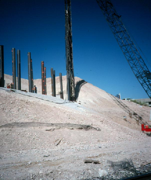
5 Figure 9-37
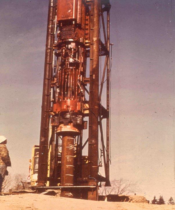
6 Figure 9-38
7

8
9

10

11
12

13
14 Driving System Analysis Fundamental pile driving mechanism EN approach Wave equation approach
15 The Fundamental Pile Driving Formula Hammer Energy = Work of Soil Resistance W h = R s R = W h s W h R S
16 The EN Bearing Graph Safe Load R W h R = 2W h s+0.1 1/8 1/16 1/24 1/32 Set s
17 R Limit of Driveability For Given Load Find Blow Count Blows per Foot
18 Construction Considerations in Design Intelligent preparation of plan and specifications can only be done by one who understands the construction operation as well as structural design concepts
19 EN Formula Factor of Safety To find F.S. between P and R, revise ENR to be dimensionally correct and compare the resulting equation for P with R R W H s R = P = WH s 2 W H(ft) s(in) WH P = ( 1/12 ) = s # R = 6P Safety Factor = 6 WH 6s
20 Dynamic Analysis of Pile Driving
21 Important Driving System Properties
22 Hammer Impact hammers and vibratory hammers - Numerous manufacturers - Variations in power source, configurations and rated energy Mechanical efficiency determines percentage rated energy transmitted to the pile - Typical values are 50% for air-steam, 70% for diesel and 90% for hydraulic Force wave shape characteristics are different for different hammer types - Affects pile stress and pile penetration
23 Pile and Appurtenances (Cushions, Helmets, etc.) Stiffness of appurtenances (e.g., hammer cushion) = AE/t - Major effect on blow count and stress transfer to the pile - Must not degrade during driving resulting in decreasing blow count and increasing pile stress Cross-sectional sectional area of pile is major factor in driveability - The hammer energy is absorbed in strain rather than performing work (i.e., penetrating pile) for long piles with small c/s area
24 Soil Setup Relaxation Important soil properties - Quake - Damping Total soil resistance to be overcome during driving to estimated length
25 Wave Equation Methodology
26 Analysis Procedure 1. Soil model and ultimate capacity assumed. 2. Analysis set in motion by selecting hammer efficiency. 3. Impact velocity of hammer mass elements calculated from efficiency. 4. For each time step, the acceleration, velocity, force, and displacement for each element and the pile toe are calculated based on force equilibrium (F = ma). 5. Process continues until pile toe rebounds. 6. Final set calculated for capacity.
27 Wave Equation Applications Develop driving criterion Blow count for a required ultimate capacity blow count for capacity as a function of energy/stroke Check driveability Blow count vs. Penetration depth Driving stresses vs penetration depth Determine optimal driving equipment Driving time Refined matching analysis Adjust input parameters to fit dynamic measurements
28 IMPORTANT NOTES The wave equation analysis CANNOT determine pile length Does the method determine capacity?
29 Input to Wave Equation Analysis Hammer - Model - Stroke and Stroke Control - Any Modifications Driving System - Helmet Weight (including Striker Plate & Cushions) - Hammer Cushion Material (E, A, t, e r ) - Pile Cushion Material (E, A, t, e r )
30 Input to Wave Equation Analysis Pile - Length, - Cross Sectional Area - Taper or Other Non-uniformities - Specific Weight - Splice Details - Design Load - Ultimate Capacity - Pile Toe Protection
31 Input to Wave Equation Analysis Soil - Boring Locations with Elevations - Soil Descriptions - N-values or Other Strength Parameters vs Depth - Elevation of Excavation - Elevation of Pile Cut-off - Elevation of Water Table - Scour Depth or Other Later Excavations
32 Pile Driving and Equipment Data Form Contract No.: Project: County: R a m Anvil Structure Name and/or No.: Pile Driving Contractor or Subcontractor: (Piles driv en by) Manufacturer: Model No.: Hammer Type: Serial No.: Manufacturers Maximum Rated Energy: (ft-lbs) Hammer Stroke at Maximum Rated Energy: (ft) Range in Operating Energy: to (ft-lbs) Range in Operating Stroke: to (ft) Ram Weight: (kips) Modifications: Striker Weight: (kips) Diam eter: (in) Plate Thickness: (in) Material #1 Material #2 (for Composite Cushion) Name: Name: Hammer Area: (in 2 ) Area: (in 2 ) Cushion Thickness/Plate: (in) Thickness /Plate: (in) No. of Plates: No. of Plates: Total Thickness of Hammer Cushion: Hel met (Drive Head) Weight: (kips) Pile Material: Cushion Area: (in 2 ) Thickness /Sheet: (in) No. of Sheets: Total Thickness of Pile Cushion: (in) Pile Pile Type: Wall Thickness: (in) Taper: Cross Sectional Area: (in 2 ) Weight/Ft: Ordered Length: (ft) Design Load: (kips) Ultimate Pile Capacity: (kips) Description of Splice: Driv ing Shoe/Closure Plate Description: Subm itted By: Telephone No.: Date: Fax No.:
33 Output from Wave Equation Analysis For a given hammer, driving system, pile and soil model combination, the WEA output includes the following: - Predicted blow count - Pile stresses - Delivered hammer energy
34 Example Output from Wave Equation Analysis Output is usually plotted for interpretation R ult Kips WAVE EQUATION SUMMARY Blow Count BPF Stroke Ft. Tensile Stress Ksi Compressive Stress Ksi Transfer Energy Ft-Kip
35 Interpretation of WEA Output Output is usually plotted for interpretation Following plots are usually created - Blow count vs resistance - Blow count vs stress Bearing Graph Constant stroke for air-steam hammer
36 Diesel Hammer at Constant Stroke Ru, Kips d e f Stroke (ft) 5.0 Ru =180 Kips
37 Variable Stroke Diesel Hammer 9 8 d Stroke ft e Ru = 180 Kips f BPI (b)
38 Driving Stresses In almost all cases, the highest stress levels in a pile occur during pile driving High driving stresses are necessary to achieve pile penetration WEA can predict driving stresses Compare predicted stresses to safe stress levels Table 9-109
39 General Criteria for Pile Driveability Acceptable driving stresses - Table Hammer blows between 30 to 144 bpf for friction piles and higher blows of short duration for end bearing piles
40 Example 9-49 Example: Determine If The 14 Square Concrete Pile Can Be Driven To A Driving Capacity Of 225 Kips By Using The Wave Equation Output Summary. Assume The Concrete Compressive Strength Is 4000 psi And The Pile Prestress Force Is 700 psi. R ult Kips WAVE EQUATION OUTPUT SUMMARY Blow Count BPF Stroke Ft. Tensile Stress Ksi Compressive Stress Ksi
41 Solution Acceptable driveability depends on achieving the hammer blows between 30 and 144 bpf as the driving resistance and allowable compressive and tensile stresses are not exceeded At R ult = 225 kips, blow count = 63 bpf - Between 30 and 144 bpf - Okay
42 Solution Based on Table Allowable compressive stress Maximum compressive stress from WEA = 1.96 ksi = 1,960 psi < 2,700 psi - Okay 0.85 f' c - f pe = = 2700 psi
43 Solution Based on Table Allowable tensile stress 3 (f' c ) 1/2 +f pe = = 890 psi Maximum tensile stress from WEA = ksi = 730 psi < 890 psi - Okay Analyzed driving system is approved
44 Pile Length Wave Equation Pile Length 80 Pile Length 120 Engineering News Formula All Lengths Blow Per Foot Resistance - Tons
45 Student Exercise 8 The soil profile shows the calculated driving resistance in each soil layer at each footing for the proposed 12 diameter steel pipe piles (fy( fy=36 ksi). Using maximum driving resistance at any footing, find the anticipated maxiumum driving stress and blow count from wave equation summaries shown for 3 pile sizes. Compare these values to the recommended friction piles values for blow count and driving stress to determine minimum acceptable pile wall thickness for the pipe piles at this site
46 Student Exercise 8 Soil Profile *10 T *50 T *30 T *10 T *10 T *10 T *10 T *120 T *120 T *120 T *120 T *120 T
47 Student Exercise 8 - Summaries GRLWEAP S & F STUDENT EXERCISE WALL THICKNESS R ult Kips Bl Ct bpf Stroke (eq. Ft) Min str. ksi Max str. ksi Enthru kipft GRLWEAP S & F STUDENT EXERCISE WALL THICKNESS R ult Kips Bl Ct bpf Stroke (eq. Ft) Min str. ksi Max str. ksi Enthru kipft GRLWEAP S & F STUDENT EXERCISE WALL THICKNESS R ult Kips Bl Ct bpf Stroke (eq. Ft) Min str. ksi Max str. ksi Enthru kipft
48 Student Exercise 8 - Solution Pile 1: wall thickness (9.77 in 2 ) Maximum Stress 42 Blow Count 112 Pile 2: wall thickness (12.19 in 2 ) Maximum Stress 36 Blow Count 73 Pile 3: wall thickness (14.60 in 2 ) Maximum Stress 30.4 Blow Count 59 OK N.G. Select Pile 3, Wall Thickness, Which meets both the Blow Count and Stress Criteria.
49 Student Exercise 9 -Hammer Approval Pile Design capacity = 115k Pile Driving resistance = 300k Should you accept the hammer?
50 Student Exercise 9 WEA Output
51 Student Exercise 9 Plots of WEA Output
52 Student Exercise 9 Solution Summary Acceptable Driving Stresses: Maximum Compressive Stress = (0.85 5,000 psi) 700 psi = 3,550 psi Maximum Tensile Stress = (3 5,000 psi) psi = 912 psi Acceptable Blow Count Range: blows/foot Wave Equation Results: 300 Kips Driving Resistance Max (compressive) stress = 1.9 ksi = 1,900 psi < 3,550 psi okay Min (tensile) stress = ksi = -280 psi < -912 psi okay Blow Count = 47 bpf between 30 & 144 bpf okay HAMMER APPROVED
53 Learning Outcomes At the end of this session, the participant will be able to: - Recall pile driving equipment - Review wave equation analysis - Assess pile driveability
54 Any Questions? Any Questions? THE ROAD TO UNDERSTANDING SOILS AND FOUNDATIONS
GLOSSARY OF TERMINOLOGY
 GLOSSARY OF TERMINOLOGY AUTHORIZED PILE LENGTHS - (a.k.a. Authorized Pile Lengths letter) Official letter stating Engineer's recommended length of concrete piles to be cast for construction of foundation.
Proceedings of the ASME 28 TH International Conference on Ocean, Offshore and Arctic Engineering OMAE2009 May 31 June 5, 2009, Honolulu, Hawaii, USA
 Proceedings of the ASME 28 TH International Conference on Ocean, Offshore and Arctic Engineering OMAE2009 May 31 June 5, 2009, Honolulu, Hawaii, USA OMAE2009-80163 CAPWAP AND REFINED WAVE EQUATION ANALYSES
PROVA DINAMICA SU PALI IN ALTERNATIVA ALLA PROVA STATICA. Pile Dynamic Load test as alternative to Static Load test
 PROVA DINAMICA SU PALI IN ALTERNATIVA ALLA PROVA STATICA Pile Dynamic Load test as alternative to Static Load test Gorazd Strnisa, B.Sc.Civ.Eng. SLP d.o.o. Ljubljana ABSTRACT Pile Dynamic test is test
High Strain Dynamic Load Testing of Drilled Shafts
 Supplemental Technical Specification for High Strain Dynamic Load Testing of Drilled Shafts SCDOT Designation: SC-M-712 (9/15) September 3, 2015 1.0 GENERAL This work shall consist of performing high-strain
Dynamic Load Testing of Helical Piles
 Dynamic Load Testing of Helical Piles ANNUAL KANSAS CITY SPECIALTY SEMINAR 2014 JANUARY 10, 2014 Jorge Beim JWB Consulting LLC Pile Dynamics, Inc. Main Topics Brief description of the Dynamic Load Test
PDCA Driven-Pile Terms and Definitions
 PDCA Driven-Pile Terms and Definitions This document is available for free download at piledrivers.org. Preferred terms are descriptively defined. Potentially synonymous (but not preferred) terms are identified
PILE FOUNDATION CONSTRUCTION INSPECTION
 ILLINOIS DEPARTMENT OF TRANSPORTATION SPECIFIC TASK TRAINING PROGRAM PILE FOUNDATION CONSTRUCTION INSPECTION S 19 CLASS REFERENCE GUIDE Reference Guide Available online at: http://www.dot.il.gov/bridges/geotechtraining.html
Comprehensive Design Example 2: Foundations for Bulk Storage Facility
 Comprehensive Design Example 2: Foundations for Bulk Storage Facility Problem The project consists of building several dry product storage silos near an existing rail siding in an open field presently
PILE DRIVING ANALYSIS BY THE WAVE EQUATION
 PILE DRIVING ANALYSIS BY THE WAVE EQUATION For technical assistance, contact: Dr. Lee L. Lowery, Jr., P.E. Department of Civil Engineering Texas A&M University College Station, Texas 77843-3136 409-845-4395
INSTALLATION SPECIFICATION FOR DRIVEN PILES
 INSTALLATION SPECIFICATION FOR DRIVEN PILES PDCA 103-07 PDCA Approved August 2007 PDCA Technical Committee Pile Driving Contractors Association www.piledrivers.org info@piledrivers.org 2007, Pile Driving
SECTION 700 STRUCTURES SECTION 701 DRIVEN PILING MATERIALS. 701.02 Materials Materials shall be in accordance with the following:
 701.03 SECTION 700 STRUCTURES SECTION 701 DRIVEN PILING 10 701.01 Description This work shall consist of furnishing and driving foundation piles of the type and dimensions specified including cutting off
METHOD STATEMENT HIGH STRIAN DYNAMIC TESTING OF PILE. Prepared by
 METHOD STATEMENT HIGH STRIAN DYNAMIC TESTING OF PILE Prepared by Infratech ASTM CO., LTD. Contents Chapter Description Page Contents...... 1 List of Appendix. 1 1. Introduction.. 2 2. Test Method..2 3.
Step 11 Static Load Testing
 Step 11 Static Load Testing Test loading is the most definitive method of determining load capacity of a pile. Testing a pile to failure provides valuable information to the design engineer and is recommended
CHAPTER 9 LONG TERM MONITORING AT THE ROUTE 351 BRIDGE
 CHAPTER 9 LONG TERM MONITORING AT THE ROUTE 351 BRIDGE 9.1 INTRODUCTION An important reason that composite piles have not gained wide acceptance in the civil engineering practice is the lack of a long
Page B-1 Hubbell Power Systems, Inc. All Rights Reserved Copyright 2014 LOAD TESTS
 Page B-1 Hubbell Power Systems, Inc. All Rights Reserved Copyright 2014 Appendix B CONTENTS STATIC (TIEBACKS)... B-3 STATIC AXIAL (COMPRESSION/TENSION)... B-6 STATIC (LATERAL)... B-9 CAPACITY VERIFICATION
Driven Concrete Pile Foundation Monitoring With Embedded Data Collector System
 Driven Concrete Pile Foundation Monitoring With Embedded Data Collector System Rodrigo Herrera 1, P.E., Lawrence E. Jones 2, P.E., Peter Lai 3, P.E. 1 Florida Department of Transportation, Geotechnical
FOUNDATION DESIGN. Instructional Materials Complementing FEMA 451, Design Examples
 FOUNDATION DESIGN Proportioning elements for: Transfer of seismic forces Strength and stiffness Shallow and deep foundations Elastic and plastic analysis Foundation Design 14-1 Load Path and Transfer to
METHOD OF STATEMENT FOR STATIC LOADING TEST
 Compression Test, METHOD OF STATEMENT FOR STATIC LOADING TEST Tension Test and Lateral Test According to the American Standards ASTM D1143 07, ASTM D3689 07, ASTM D3966 07 and Euro Codes EC7 Table of Contents
EXAMPLE 1 DESIGN OF CANTILEVERED WALL, GRANULAR SOIL
 EXAMPLE DESIGN OF CANTILEVERED WALL, GRANULAR SOIL A sheet pile wall is required to support a 2 excavation. The soil is uniform as shown in the figure. To take into account the friction between the wall
PILE FOUNDATIONS FM 5-134
 C H A P T E R 6 PILE FOUNDATIONS Section I. GROUP BEHAVIOR 6-1. Group action. Piles are most effective when combined in groups or clusters. Combining piles in a group complicates analysis since the characteristics
The advantages and disadvantages of dynamic load testing and statnamic load testing
 The advantages and disadvantages of dynamic load testing and statnamic load testing P.Middendorp & G.J.J. van Ginneken TNO Profound R.J. van Foeken TNO Building and Construction Research ABSTRACT: Pile
System. Stability. Security. Integrity. 150 Helical Anchor
 Model 150 HELICAL ANCHOR System PN #MBHAT Stability. Security. Integrity. 150 Helical Anchor System About Foundation Supportworks is a network of the most experienced and knowledgeable foundation repair
vulcanhammer.net This document downloaded from
 This document downloaded from vulcanhammer.net since 1997, your source for engineering information for the deep foundation and marine construction industries, and the historical site for Vulcan Iron Works
Micropiles Reduce Costs and Schedule for Merchant RR Bridge Rehabilitation
 Micropiles Reduce Costs and Schedule for Merchant RR Bridge Rehabilitation Jeff R. Hill, P.E. Hayward Baker Inc. 111 W. Port Plaza Drive Suite 600 St. Louis, MO 63146 314-542-3040 JRHill@HaywardBaker.com
SUPPLEMENTAL TECHNICAL SPECIFICATIONS BI-DIRECTIONAL STATIC LOAD TESTING OF DRILLED SHAFTS
 July 14, 2015 1.0 GENERAL BI-DIRECTIONAL STATIC LOAD TESTING OF DRILLED SHAFTS This work shall consist of furnishing all materials, equipment, labor, and incidentals necessary for conducting bi-directional
Outline MICROPILES SUBJECT TO LATERAL LOADING. Dr. Jesús Gómez, P.E.
 MICROPILES SUBJECT TO LATERAL LOADING Dr. Jesús Gómez, P.E. Micropile Design and Construction Seminar Las Vegas, NV April 3-4, 2008 Outline When are micropiles subject to lateral load? How do we analyze
Stability. Security. Integrity.
 Stability. Security. Integrity. PN #MBHPT Foundation Supportworks provides quality helical pile systems for both new construction and retrofit applications. 288 Helical Pile System About Foundation Supportworks
SPECIFICATION FOR DYNAMIC CONSOLIDATION / DYNAMIC REPLACEMENT
 SPECIFICATION FOR DYNAMIC CONSOLIDATION / DYNAMIC REPLACEMENT 1.0 SOIL IMPROVEMENT 1.1 General Soil Investigation Information are provided in Part B1 annex as a guide to the Contractor for his consideration
EDUH 1017 - SPORTS MECHANICS
 4277(a) Semester 2, 2011 Page 1 of 9 THE UNIVERSITY OF SYDNEY EDUH 1017 - SPORTS MECHANICS NOVEMBER 2011 Time allowed: TWO Hours Total marks: 90 MARKS INSTRUCTIONS All questions are to be answered. Use
SAMPLE GUIDE SPECIFICATIONS FOR OSTERBERG CELL LOAD TESTING OF DEEP FOUNDATIONS
 Page 1 of 9 SAMPLE GUIDE SPECIFICATIONS FOR OSTERBERG CELL LOAD TESTING OF DEEP FOUNDATIONS 1. GENERAL REQUIREMENTS 1. Description of Work: This work consists of furnishing all materials, equipment and
STATNAMIC : Pile Load Testing Equipment
 STATNAMIC : Pile Load Testing Equipment Today's taller buildings, heavier loads, and increased construction costs require the use of large-diameter, drilled pier foundation systems. As such, the demand
Design, Testing and Automated Monitoring of ACIP Piles in Residual Soils
 Design, Testing and Automated Monitoring of ACIP Piles in Residual Soils Stephen W. Lacz 1, M. ASCE, P.E. and Richard C. Wells 2, F. ASCE, P.E. 1 Senior Professional, Trigon Kleinfelder, Inc., 313 Gallimore
External Wrapping of Steel Riser Pipe. Case Study HJ3 CS200902
 External Wrapping of Steel Riser Pipe Case Study HJ3 CS200902 Introduction Refineries process a wide variety of petroleum products. As part of the process, they rely on cooling towers, which recycle water
Kentucky Lake Bridge Pile Load Testing Overview Ohio Transportation Engineering Conference Columbus, Ohio 10/28/2015
 Kentucky Lake Bridge Pile Load Testing Overview Ohio Transportation Engineering Conference Columbus, Ohio 10/28/2015 Presented by: Jeff Dunlap, P.E. Terracon Consultants 1 Project Site Kentucky Official
Design and installation of steel open end piles in weathered basalt. Luc Maertens*
 Design and installation of steel open end piles in weathered basalt Luc Maertens* * Manager Engineering Department Besix, Belgium, lmaertens@besix.com Associate Professor Catholic University Leuven, luc.maertens@bwk.kuleuven.ac.be
Dynamic Pile Analysis Using CAPWAP and Multiple Sensors Camilo Alvarez 1, Brian Zuckerman 2, and John Lemke 3
 Dynamic Pile Analysis Using CAPWAP and Multiple Sensors Camilo Alvarez 1, Brian Zuckerman 2, and John Lemke 3 1 GRL Engineers, Inc. Los Angeles, California. (661) 259-2977 2 Berkel & Company. San Francisco,
SAFE A HEAD. Structural analysis and Finite Element simulation of an innovative ski helmet. Prof. Petrone Nicola Eng.
 SAFE A HEAD Structural analysis and Finite Element simulation of an innovative ski helmet Prof. Petrone Nicola Eng. Cherubina Enrico Goal Development of an innovative ski helmet on the basis of analyses
Durability, Versatility
 Precast Concrete Piles Provide Durability, Versatility Precast, prestressed piles offer a range of advantages, particularly in corrosive environments, but proper installation is the key to maximizing the
SECTION 1 GENERAL REQUIREMENTS
 Page 1 of 6 SECTION 1 GENERAL REQUIREMENTS 1. SCOPE OF WORK: The work to be performed under the provisions of these documents and the contract based thereon includes furnishing all labor, equipment, materials,
PTS HELICAL PIERS INSTALLATION SPECIFICATIONS NOTICE
 FORM A PTS HELICAL PIERS INSTALLATION SPECIFICATIONS NOTICE The following suggested specifications are written as a guide to assist the specifier in writing his own specifications. Specific circumstances
Instrumented Becker Penetration Test for Liquefaction Assessment in Gravelly Soils
 Instrumented Becker Penetration Test for Liquefaction Assessment in Gravelly Soils Mason Ghafghazi 1, PhD, PEng. Jason DeJong 2, Professor Department of Civil and Environmental Engineering University of
Chapter 8. Flexural Analysis of T-Beams
 Chapter 8. Flexural Analysis of T-s 8.1. Reading Assignments Text Chapter 3.7; ACI 318, Section 8.10. 8.2. Occurrence and Configuration of T-s Common construction type.- used in conjunction with either
EN 1997-1 Eurocode 7. Section 10 Hydraulic Failure Section 11 Overall Stability Section 12 Embankments. Trevor L.L. Orr Trinity College Dublin Ireland
 EN 1997 1: Sections 10, 11 and 12 Your logo Brussels, 18-20 February 2008 Dissemination of information workshop 1 EN 1997-1 Eurocode 7 Section 10 Hydraulic Failure Section 11 Overall Stability Section
ALLOWABLE LOADS ON A SINGLE PILE
 C H A P T E R 5 ALLOWABLE LOADS ON A SINGLE PILE Section I. BASICS 5-1. Considerations. For safe, economical pile foundations in military construction, it is necessary to determine the allowable load capacity
Instrumentations, Pile Group Load Testing, and Data Analysis Part II: Design & Analysis of Lateral Load Test. Murad Abu-Farsakh, Ph.D., P.E.
 Instrumentations, Pile Group Load Testing, and Data Analysis Part II: Design & Analysis of Lateral Load Test Murad Abu-Farsakh, Ph.D., P.E. Louisiana Transportation Research Center Louisiana State University
STRUCTURES. 1.1. Excavation and backfill for structures should conform to the topic EXCAVATION AND BACKFILL.
 STRUCTURES 1. General. Critical structures may impact the integrity of a flood control project in several manners such as the excavation for construction of the structure, the type of foundation, backfill
Engineered, Time-Tested Foundation Repairs for Settlement in Residential and Light Commercial Structures. The Leading Edge.
 TM TM Engineered, Time-Tested Foundation Repairs for Settlement in Residential and Light Commercial Structures. SM The Leading Edge. 10 One Major Causes of foundation settlement or more conditions may
1997 Uniform Administrative Code Amendment for Earthen Material and Straw Bale Structures Tucson/Pima County, Arizona
 for Earthen Material and Straw Bale Structures SECTION 70 - GENERAL "APPENDIX CHAPTER 7 - EARTHEN MATERIAL STRUCTURES 70. Purpose. The purpose of this chapter is to establish minimum standards of safety
Pile Driving Analysis Via Dynamic Loading Test
 University of Southern Queensland Faculty of Engineering and Surveying Pile Driving Analysis Via Dynamic Loading Test A dissertation submitted by Mr. Yu Wah, YU In fulfillment of the requirements of Courses
An Automatic Kunzelstab Penetration Test
 An Automatic Kunzelstab Penetration Test Yongyuth Sirisriphet 1, Kitidech Santichaianant 2 1 Graduated student: Faculty of Industrial Education in and Technology. King Mongkut's University of Technology
ATLAS RESISTANCE Pier Foundation Systems
 ATLAS RESISTANCE Pier Foundation Systems Foundation Repair Systems for Civil Construction Applications: Residential, Commercial, Industrial Atlas Resistance Piers have been used to restore and/or stabilize
Measuring the Condition of Prestressed Concrete Cylinder Pipe
 Measuring the Condition of Prestressed Concrete Cylinder Pipe John Marshall, P.E.I, I J.W. Marshall and Associates, and Paul S. Fisk, President NDT Corporation Introduction Prestressed Concrete Cylinder
Local Authority Building Control Technical Information Note 3 Driven and In-situ Piled Foundations
 Local Authority Building Control Technical Information Note 3 Driven and In-situ Piled Foundations Cambridge City Council - East Cambridgeshire District Council - Fenland District Council, Huntingdonshire
Site Auditing for Building Works. This practice note provides details of the strategy on auditing building works by the Buildings Department (BD).
.") Buildings Department Practice te for Authorized Persons, Registered Structural Engineers and Registered Geotechnical Engineers ADM-18 Site Auditing for Building Works Introduction This practice note provides
Buildings Department Practice te for Authorized Persons, Registered Structural Engineers and Registered Geotechnical Engineers ADM-18 Site Auditing for Building Works Introduction This practice note provides
How To Model A Shallow Foundation
 Finite Element Analysis of Elastic Settlement of Spreadfootings Founded in Soil Jae H. Chung, Ph.D. Bid Bridge Software Institute t University of Florida, Gainesville, FL, USA Content 1. Background 2.
DEM modelling of the dynamic penetration process on Mars as a part of the NASA InSight Mission
 Proceedings of the 4th European Young Geotechnical Engineers Conference (EYGEC), Durham, UK Osman, A.S. & Toll, D.G. (Eds.) 05 ISBN 978-0-9933836-0 DEM modelling of the dynamic penetration process on Mars
Jack-in Piling Environmental Friendly Piling System
 Jack-in Piling Environmental Friendly Piling System Part 1 - Chris Loh 7 Nov 12 CSC HOLDINGS LIMITED Gracious Piling Environmental Friendly Low Noise No Vibration Jack-in Piling How Many Decibels? Permissible
MODEL-SIZED AND FULL-SCALE DYNAMIC PENETRATION TESTS ON DAMPING CONCRETE
 MODEL-SIZED AND FULL-SCALE DYNAMIC PENETRATION TESTS ON DAMPING CONCRETE Robert Scheidemann, Eva-Maria Kasparek, Karsten Müller, Bernhard Droste, Holger Völzke BAM Federal Institute for Materials Research
4.3 Results... 27 4.3.1 Drained Conditions... 27 4.3.2 Undrained Conditions... 28 4.4 References... 30 4.5 Data Files... 30 5 Undrained Analysis of
 Table of Contents 1 One Dimensional Compression of a Finite Layer... 3 1.1 Problem Description... 3 1.1.1 Uniform Mesh... 3 1.1.2 Graded Mesh... 5 1.2 Analytical Solution... 6 1.3 Results... 6 1.3.1 Uniform
INSITU TESTS! Shear Vanes! Shear Vanes! Shear Vane Test! Sensitive Soils! Insitu testing is used for two reasons:!
 In-situ Testing! Insitu Testing! Insitu testing is used for two reasons:! To allow the determination of shear strength or penetration resistance or permeability of soils that would be difficult or impossible
Geotechnical Measurements and Explorations Prof. Nihar Ranjan Patra Department of Civil Engineering Indian Institute of Technology, Kanpur
 Geotechnical Measurements and Explorations Prof. Nihar Ranjan Patra Department of Civil Engineering Indian Institute of Technology, Kanpur Lecture No. # 13 (Refer Slide Time: 00:18) So last class, it was
5/1/2013. Topics. The challenge is to better maintain native characteristics of soils during and after construction
 PIN Foundations Topics Applications Design and Construction Flow Control Credits www.pinfoundations.com Copyright 2008, Pin Foundations, Inc. Curtis Hinman WSU Extension Faculty, Watershed Ecologist chinman@wsu.edu
The International Workshop on Micropiles, 2007
 MICROPILE FOUNDATION REPAIR AND UNDERPINNING, ARTS AND SCIENCE MUSEUM, UNIVERSITY OF PUERTO RICO, MAYAGUEZ Presented at: International Society of Micropiles (ISM) The International Workshop on Micropiles,
Scour and Scour Protection
 Design of Maritime Structures Scour and Scour Protection Steven A. Hughes, PhD, PE Coastal and Hydraulics Laboratory US Army Engineer Research and Development Center Waterways Experiment Station 3909 Halls
DESIGN OF PILES AND PILE GROUPS CONSIDERING CAPACITY, SETTLEMENT, AND NEGATIVE SKIN FRICTION
 DESIGN OF PILES AND PILE GROUPS CONSIDERING CAPACITY, SETTLEMENT, AND NEGATIVE SKIN FRICTION Introduction Bengt H. Fellenius, Dr.Tech., P.Eng. Background Notes for Demo Example for UniPile at www.unisoftltd.com
LEGACY REPORT ER-5110. www.icc-es.org. ICC Evaluation Service, Inc. Reissued November 1, 2003. Legacy report on the 1997 Uniform Building Code
 LEGACY REPORT Reissued November 1, 2003 ICC Evaluation Service, Inc. www.icc-es.org Business/Regional Office # 5360 Workman Mill Road, Whittier, California 90601 # (562) 699-0543 Regional Office # 900
DIRT DWELLING. and your. www.pinfoundations.com. Pin Foundations Inc., 2008
 DIRT and your DWELLING 2008 Pin Foundations Inc., 2008 If we accept that preserving soil in its native condition is necessary, then how do we build? Utilities? Roads? Foundations? Typical Strip, Transfer,
MATERIALS AND MECHANICS OF BENDING
 HAPTER Reinforced oncrete Design Fifth Edition MATERIALS AND MEHANIS OF BENDING A. J. lark School of Engineering Department of ivil and Environmental Engineering Part I oncrete Design and Analysis b FALL
A DEEP FOUNDATION COMPARISON: DRIVEN vs BORED PILES. Professor s Driven Pile Institute Logan, UT June 26, 2013
 A DEEP FOUNDATION COMPARISON: DRIVEN vs BORED PILES Presented By: Professor s Driven Pile Institute Logan, UT June 26, 2013 Billy Camp, PE, D.GE Technical Principal/Vice President S&ME, Inc. Charleston,
How to Design Helical Piles per the 2009 International Building Code
 ABSTRACT How to Design Helical Piles per the 2009 International Building Code by Darin Willis, P.E. 1 Helical piles and anchors have been used in construction applications for more than 150 years. The
Lymon C. Reese & Associates LCR&A Consulting Services Tests of Piles Under Axial Load
 Lymon C. Reese & Associates LCR&A Consulting Services Tests of Piles Under Axial Load Nature of Services The company has a long history of performance of tests of piles and pile groups under a variety
SECTION 3 DESIGN OF POST TENSIONED COMPONENTS FOR FLEXURE
 SECTION 3 DESIGN OF POST TENSIONED COMPONENTS FOR FLEXURE DEVELOPED BY THE PTI EDC-130 EDUCATION COMMITTEE LEAD AUTHOR: TREY HAMILTON, UNIVERSITY OF FLORIDA NOTE: MOMENT DIAGRAM CONVENTION In PT design,
DRIVEN PILE COST COMPARISON FOR TWO LARGE WISCONSIN DOT BRIDGE PROJECTS
 DRIVEN PILE COST COMPARISON FOR TWO LARGE WISCONSIN DOT BRIDGE PROJECTS Van E. Komurka, P.E., Wagner Komurka Geotechnical Group, Inc, Cedarburg, Wisconsin, USA Robert P. Arndorfer, P.E., Wisconsin Department
Water hammering in fire fighting installation
 Water hammering in fire fighting installation Forward One of major problems raised in the fire fighting network installed at Pioneer company for pharmaceutical industry /Sulaymania was the high water hammering
MICROPILE FOUNDATIONS IN KARST: STATIC AND DYNAMIC TESTING VARIABILITY
 MICROPILE FOUNDATIONS IN KARST: STATIC AND DYNAMIC TESTING VARIABILITY Jesús Gómez, Ph.D., P.E Allen Cadden, P.E. O. Christopher Webster, P.E. Schnabel Engineering, Inc. Schnabel Engineering, Inc. Schnabel
PERFORMANCE EVALUATION OF A LARGE SCALE PILE LOAD TESTING PROGRAM IN LIGHT OF NEWLY DEVELOPED LRFD PARAMETERS. Reference
 Geotechnical Engineering Research Laboratory One University Avenue Lowell, Massachusetts 01854 Tel: (978) 934-2277 Fax: (978) 934-3046 e-mail: Samuel_Paikowsky@uml.edu web site: http://geores.caeds.eng.uml.edu
VERTICAL MICROPILE LATERAL LOADING. Andy Baxter, P.G.
 EFFICIENT DESIGN OF VERTICAL MICROPILE SYSTEMS TO LATERAL LOADING Dr. Jesús Gómez, P.E. PE Andy Baxter, P.G. Outline When are micropiles subject to lateral load? How do we analyze them? Shear Friction
ENCE 4610 Foundation Analysis and Design
 This image cannot currently be displayed. ENCE 4610 Foundation Analysis and Design Shallow Foundations Total and Differential Settlement Schmertmann s Method This image cannot currently be displayed. Strength
Foundation Underpinning Process and Relationship with Groundwater in West- Central Florida
 Foundation Underpinning Process and Relationship with Groundwater in West- Central Florida Ahmed Said, PhD, PE Principal Engineering Consultant, Sinkhole Geotech, Inc. e-mail: admin@sinkholegeotech.com
Type of Force 1 Axial (tension / compression) Shear. 3 Bending 4 Torsion 5 Images 6 Symbol (+ -)
 Shear. 3 Bending 4 Torsion 5 Images 6 Symbol (+ -)") Cause: external force P Force vs. Stress Effect: internal stress f 05 Force vs. Stress Copyright G G Schierle, 2001-05 press Esc to end, for next, for previous slide 1 Type of Force 1 Axial (tension /
Cause: external force P Force vs. Stress Effect: internal stress f 05 Force vs. Stress Copyright G G Schierle, 2001-05 press Esc to end, for next, for previous slide 1 Type of Force 1 Axial (tension /
ITEM #0702770 OSTERBERG CELL LOAD TESTING OF DRILLED SHAFT
 ITEM #0702770 OSTERBERG CELL LOAD TESTING OF DRILLED SHAFT Description: This work shall consist of furnishing all materials, equipment and labor necessary for conducting an Osterberg Cell (O-Cell) Load
Session 5D: Benefits of Live Load Testing and Finite Element Modeling in Rating Bridges
 Session 5D: Benefits of Live Load Testing and Finite Element Modeling in Rating Bridges Douglas R. Heath P.E., Structural Engineer Corey Richard P.E., Project Manager AECOM Overview Bridge Testing/Rating
Incorporating Innovative Materials for Seismic Resilient Bridge Columns
 Incorporating Innovative Materials for Seismic Resilient Bridge Columns WSDOT Including Contributions from: Dr. M. Saiid Saiidi University Nevada, Reno Brain Nakashoji University Nevada, Reno Presentation
The Stabilizer TM. Benefits. www.griptite.com. Supplemental support system for sagging beams and floor joists within a crawl space
 The Stabilizer TM Supplemental support system for sagging beams and floor joists within a crawl space Pre-drilled holes in steel plate allow for connection to beam or floor joists. Benefits Levels and
LABORATORY DETERMINATION OF CALIFORNIA BEARING RATIO
 LABORATORY DETERMINATION OF CALIFORNIA BEARING RATIO STANDARD IS: 2720 (Part 16) 1979. DEFINITION California bearing ratio is the ratio of force per unit area required to penetrate in to a soil mass with
DIVISION: 31 00 00 EARTHWORK SECTION: 31 63 00 BORED PILES REPORT HOLDER: HUBBELL POWER SYSTEMS, INC.
 0 ICC ES Report ICC ES (800) 4 6587 (56) 699 054 www.icc es.org 000 Most Widely Accepted and Trusted ESR 794 Reissued 05/05 This report is subject to renewal 05/06. DIVISION: 00 00 EARTHWORK SECTION: 6
SECTION 3 DESIGN OF POST- TENSIONED COMPONENTS FOR FLEXURE
 SECTION 3 DESIGN OF POST- TENSIONED COMPONENTS FOR FLEXURE DEVELOPED BY THE PTI EDC-130 EDUCATION COMMITTEE LEAD AUTHOR: TREY HAMILTON, UNIVERSITY OF FLORIDA NOTE: MOMENT DIAGRAM CONVENTION In PT design,
STATIC PILE LOAD TEST MANUAL. GEOTECHNICAL CONTROL PROCEDURE GCP-18 Revision #4
 STATIC PILE LOAD TEST MANUAL GEOTECHNICAL CONTROL PROCEDURE GCP-18 Revision #4 AUGUST 2015 GEOTECHNICAL CONTROL PROCEDURE: STATIC PILE LOAD TEST MANUAL GCP-18 Revision #4 STATE OF NEW YORK DEPARTMENT
Geotechnical Investigation Reports and Foundation Recommendations - Scope for Improvement - Examples
 Geotechnical Investigation Reports and Foundation Recommendations - Scope for Improvement - Examples Prof. V.S.Raju (Formerly: Director, IIT Delhi & Professor and Dean, IIT Madras) Email: rajuvs_b@yahoo.com
Figure A-1. Figure A-2. continued on next page... HPM-1. Grout Reservoir. Neat Cement Grout (Very Flowable) Extension Displacement Plate
 Extension Displacement Plate") Addendum HELICAL PULLDOWN Micropile (HPM) Introduction The HPM is a system for constructing a grout column around the shaft of a standard Helical Screw Foundation (see Figure A1). To begin the process,
Addendum HELICAL PULLDOWN Micropile (HPM) Introduction The HPM is a system for constructing a grout column around the shaft of a standard Helical Screw Foundation (see Figure A1). To begin the process,
Geotechnical Building Works (GBW) Submission Requirements
 Submission Requirements") Building Control (Amendment) Act 2012 and Regulations 2012: Geotechnical Building Works (GBW) Submission Requirements Building Engineering Group Building and Construction Authority May 2015 Content : 1.
Building Control (Amendment) Act 2012 and Regulations 2012: Geotechnical Building Works (GBW) Submission Requirements Building Engineering Group Building and Construction Authority May 2015 Content : 1.
Load Testing of Drilled Shaft Foundations in Limestone, Nashville, TN Dan Brown, P.E., Ph.D.
 Dan A. Brown and Associates Consulting Geotechnical Engineers 300 Woodland Rd. (423)942-8681 Sequatchie, TN 37374 fax:(423)942-8687 Load Testing of Drilled Shaft Foundations in Limestone, Nashville, TN
Practice of rapid load testing in Japan
 Chapter 4 Practice of rapid load testing in Japan T. Matsumoto Department of Civil Eng., Kanazawa University, Kakuma-machi, Kanazawa, Japan SUMMARY This paper reviews the research activities for standardisation
How To Design A Foundation
 The Islamic university - Gaza Faculty of Engineering Civil Engineering Department CHAPTER (2) SITE INVESTIGATION Instructor : Dr. Jehad Hamad Definition The process of determining the layers of natural
PERFORMANCE TEST REPORT. Rendered to: FORMTECH ENTERPRISES, INC. SERIES/MODEL: Truline PRODUCT TYPE: PVC Seawall
 PERFORMANCE TEST REPORT Rendered to: FORMTECH ENTERPRISES, INC. SERIES/MODEL: Truline PRODUCT TYPE: PVC Seawall Report No.: Test Dates: 04/17/12 Through: 04/18/12 Report Date: 06/13/12 130 Derry Court
Design of pile foundations following Eurocode 7-Section 7
 Brussels, 18-20 February 2008 Dissemination of information workshop 1 Workshop Eurocodes: background and applications Brussels, 18-20 Februray 2008 Design of pile foundations following Eurocode 7-Section
PVE Piling and Drilling Rigs Powerful, Versatile and Efficient. PVE Piling and Drilling Rigs B.V. Worldwide supply of specialized foundation machines
 PVE Piling and Drilling Rigs Powerful, Versatile and Efficient PVE Piling and Drilling Rigs B.V. Worldwide supply of specialized foundation machines Member of the PVE Piling and Drilling Rigs PVE Piling
ADVANCEMENTS IN STATNAMIC DATA REGRESSION TECHNIQUES
 ADVANCEMENTS IN STATNAMIC DATA REGRESSION TECHNIQUES Gray Mullins 1, Christopher L. Lewis 2, Michael D. Justason 3 ABSTRACT Until recently, the analysis of Statnamic test data has typically incorporated
Table of Contents 16.1 GENERAL... 16.1-1. 16.1.1 Overview... 16.1-1 16.1.2 Responsibilities... 16.1-1
 Table of Contents Section Page 16.1 GENERAL... 16.1-1 16.1.1 Overview... 16.1-1 16.1.2 Responsibilities... 16.1-1 16.1.2.1 Geotechnical Section/Bridge Bureau Coordination... 16.1-1 16.1.2.2 Geotechnical