Tutorial: House. Topics Covered in this Tutorial. Model a House
|
|
|
- Anna Harrell
- 7 years ago
- Views:
Transcription

1 Tutorial: House Topics Covered in this Tutorial Work area Snap Grid Layers Edit Objects View Select Mask Preferences Modeling Line Arcs Rectangle Text Hatch Primitives Extruded solid Thicken solid Surfaces Editing Move Rotate Offset Array Remove section from solid Boolean operations Shell solid Model to Sheet Section cut Drawing views and more. 1


2 In this tutorial we will construct a house starting with 3D modeling and finishing with 2D illustrations or layouts. Setting up the Drawing 1. Most newer computers will not have CPU speed problems so go to File>Preferences>Display. In the Object Type pull down menu, set the Resolution for Curve, Surface and Solid to Super Fine. 2. In the Preferences menu select Grid, set the Spacing values to 1 m, Sub-spacing to 1 and the Grid size to 30 by Also, if you don t already have it open, show the Snap Option palette (Window>Snaps). Check the To Grid option. Note: units used in this tutorial are meters. 2

3 Walls 1. In the Layer Manager, change the name of Layer 1 to curves. 2. Starting at the Origin, reproduce the series of Connected Lines shown below. The overall size of the building is 20 meters by 13 meters. 3. Switch to the Isometric View ( f ). 3
. 6. Now using the snap points indicated below, create lines for the internal partition walls.")
4 4. Select the Solid Extrude tool, using the by Thin Extrude option in the Message Line. The extrude Distance is 3m with an Offset of.3m. 5. Switch back to the Top View ( d ). 6. Now using the snap points indicated below, create lines for the internal partition walls. 4


5 7. To create the arc, select the Tangent Arc tool. Locate the arc using the snap points shown below. 8. Switch back to the Isometric view ( f ). 9. Select the Solid Extrude tool. Using the Thin Extrude option in the Message Line, extrude all of the internal walls by 3m and an Offset of.1m. When using the Thin Extrude tool, the alignment of the extruded solid can be changed by tapping the Ctrl (PC) or the Option (Mac) key. There are three alignment points for the solid to the wireframe geometry: Centered, Inside & Outside. 5

. 3.")
6 10. In the Layer Manager, create a new layer, rename the layer to walls. 11. Place all of the walls onto the wall layer. Right Mouse click in the white-space of your drawing, choose Select All>Solids. This operation will select only the solids in the drawing. Show the Edit Objects dialog box (Ctrl + i or Command + i), under the Attributes Tab, choose walls in the Layer drop down menu. Save your work. Creating the Windows 1. Create a new layer, rename it to windows, make it current and turn off the visibility of the other layers. 2. Switch to the Front View ( s ). 3. Draw a Rectangle starting at the Origin, with a Width of 1.2m and a Height of 1.4m. 4. Offset the rectangle to its inside by Switch to the Isometric View ( f ). 6
. 9. Move all of the window objects to this location dx = 1.9; dy = 0.")
 perpendicular to the internal profile of")
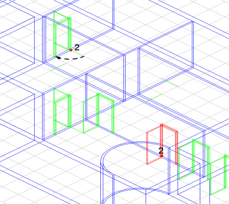
7 6. Extrude all these objects using the Midplane option in the Message Line. The Distance is Create a second Midplane Extrusion using the internal rectangle, the Distance is Move a copy of the external rectangle by 0.3m in negative y direction (hold down the Ctrl [PC] or Option [Mac] key). 9. Move all of the window objects to this location dx = 1.9; dy = 0.125; dz = Turn on the walls layer. 11. Show Grid and check the To Grid option in Snaps palette. 12. Copy this set of elements following the scheme illustrated in the picture below. 13. We need a location marker for placing the next set of windows, so draw a Line from the Midpoint of the rectangle on window number four (Grid point 4) perpendicular to the internal profile of the wall. 7
. 15. Rotate the window located at Mid 2 above by 90. 16.")
8 14. Select all parts of window number four and arrange them as shown below (pay close attention to the location of the line endpoint). 15. Rotate the window located at Mid 2 above by Move a copy of that window from that location to those illustrated below. 8
. 3.")
9 Save your work. Doors We will use the same method to create the doors that we used to create the windows with one slight variation. This variation has a huge time saving potential if you begin to incorporate it into your workflow. 1. Create a new layer, name it doors. 2. Switch to the Front View ( s ). 3. Draw a Rectangle from the Origin with a Width of 1 and a Height of Offset the rectangle to the inside by 0.05m. 5. Draw a selection fence around bottom line of the internal rectangle and extend it to the bottom line of the external rectangle. Use the selection move the lines together. tool to 9

10 6. Switch to the Isometric View ( f ). 7. Extrude the external rectangle by 0.1m. Repeat the extrude on the internal rectangle (use the same extrusion distance). 8. Subtract the second extrude from the first. 9. Extrude the internal rectangle again, this time with a distance of 0.05m 10. Change the work plane to Global in the Planes Menu. 11. Rotate it from lower left corner by Move a copy (Ctrl [PC] or Option [Mac]) of the door to the location shown in the picture. Also create the lines shown in red as a reference for locating copies of the door. 10

11 13. Select the door and choose the Linear Duplicate tool. Set the Column value to 6 and its distance to 2. Leave the Row value set to 1. Make sure the offset spacing is set to Step Offset. The most important thing is to have the Associative duplicates option checked. 14. Arrange the copied doors with a series of moving and rotating operations as illustrated in the figures below. 11

12 12

13 Window and Door Cutouts Here are some simple operations producing holes in our walls that accommodate the windows and doors. Windows. 1. Choose the Remove section from solid tool. Select the exterior wall solid, next select one of the window rectangles that we moved.3m in the negative y direction, the last step is to specify the two points that the rectangle will use to cut through the wall. Repeat operation for all of the windows. Note: You can select multiple cutout rectangles at one time, the only requirement is that the rectangles exist in the same plane. 13


14 Doors. 1. Use the Trim solid tool. Select the door frame as the trimming boundary and then select the wall as the object to trim. 14

15 Finishing Details Now we will add some finishing elements to our model. 1. Draw a Cylinder using the 1 point creation method, place center of the cylinder at the following location, X = 0.15; Y = -7.85; Z = 0; Height of 3; Diameter of 0.3. Create it in the walls layer. 2. Create a Block primitive using the 1 point creation method. This point is located at the Quadrant on the base of our curved partition wall. The values of the block are: L & W = 2; H = Subtract this solid from the wall. 4. Create another Block, this time use the 3 point creation method. Specify the points located at Mid 1 and Grid 2 of picture, the height of the block is 2.1m. 5. Subtract this block from the wall. Create a third block representing the front door. The Length is 0.1m, the Width is 1.50m and the Height is 2.1m. 15
16 6. Switch to the Top View ( d ). 7. To create the roof of the building, draw a Rectangle that is 1 meter large than the entire house. Extrude the rectangle by 2m adding a Draft Angle of -45. Move the solid in positive z direction 3 meters. Save your file. Creating your own Model to Sheet Layouts The following steps illustrate how to create your own Layouts. These steps are not always necessary because Ashlar s programs come with an assortment of predefined layouts. 1. Open a new file ( Ctrl + n or Command +n) or Menu File > New. 2. Draw a Rectangle with lower left corner point at X = 1; Y = 1, the Width is 57.40cm (we have switched Units to centimeters) and the Height is 40cm. 3. Offset the rectangle to the inside by 1 cm. Draw a selection fence around the bottom offset line, move it in the positive y axis 5 cm. 16
17 4. Using the Line tool, create one horizontal and one vertical line located at the Midpoint of the existing lines. The next few step are critical in this process. 5. Go to Window>Sheet tools. 6. Select the Drawing view tool. Create four views that are aligned with each of the squares we drew. 7. Click on upper left view to activate it, then right-click and choose Properties. Change the name to Top, the scale to 1 and the Visible Pen style to Use Object color. Click Apply and then OK. Right-click again, this time choose Change view, change the view to Top from the drop down menu. 17
18 8. Repeat operation for the remaining views. Save this file in the folder called Layouts. You can find this folder on your hard disk as a sub-folder of the Cobalt installation. Use the name House_layout.co. 9. Return to the file where you modeled the house. 10. While in Top view, make all layers visible except curves, select all and choose the Model to Sheet tool. (Make sure that all of the lines, arcs, etc. are on the curves layer. Right-Mouse-Click and choose Select All > Curves, open the Edit Objects dialog box and assign them to that layer.) 18
19 Select all of the solids (this should be the only items visible), choose House_layout.co from the Layouts drop down menu, set the scale to 0.01 and choose ignore for all pen styles but Visible, set this to Use Object Color. Now, let s modify our Model To Sheet drawing by deleting one view and adding a plan view. 11. Click on the Top view to select it, Right Click in the Top view to show the drop down menu, choose Delete. 12. Click on Front view to make it active. 13. Select the Section cut through view tool (It requires that a drawing view be selected before the tool will work). Choose the Horizontal section create mode from the Message Line. Choose the Midpoint of a wall for the cut through view, move the mouse up to place this new view where the Top view used to be. 19
20 14. Hatch is automatically generated for section views (unless you uncheck this option in Properties window of the view). The scale for the Hatch is too big, select the hatch and in the Edit Objects window set the scale to Now we have arrived at our goal. Objects in these view are linked to the 3D model and consequently any change to the model will be reflected directly on the sheet. 20

 as shown in the picture below. 3.")
21 We are going to take advantage of this linking by modifying the door we used to create the Linear duplicates. 1. Turn off all layers except walls and doors. We have decided that the doors need to be modified to create a more realistic look. Find the door used to create the Linear duplicates. 2. Draw one Circle with a Diameter of 7 and a Cube (it doesn t matter what size the cube is) as shown in the picture below. 3. Cutout the circle profile from the door and Subtract the Cube from the door, all the doors are updated in the model and in the sheet, at the same time. This completes the tutorial, save your work. 21
22 22
2013 Getting Started Guide
 2013 Getting Started Guide The contents of this guide and accompanying exercises were originally created by Nemetschek Vectorworks, Inc. Vectorworks Fundamentals Getting Started Guide Created using: Vectorworks
TABLE OF CONTENTS. INTRODUCTION... 5 Advance Concrete... 5 Where to find information?... 6 INSTALLATION... 7 STARTING ADVANCE CONCRETE...
 Starting Guide TABLE OF CONTENTS INTRODUCTION... 5 Advance Concrete... 5 Where to find information?... 6 INSTALLATION... 7 STARTING ADVANCE CONCRETE... 7 ADVANCE CONCRETE USER INTERFACE... 7 Other important
An introduction to 3D draughting & solid modelling using AutoCAD
 An introduction to 3D draughting & solid modelling using AutoCAD Faculty of Technology University of Plymouth Drake Circus Plymouth PL4 8AA These notes are to be used in conjunction with the AutoCAD software
Introduction to Autodesk Inventor for F1 in Schools
 Introduction to Autodesk Inventor for F1 in Schools F1 in Schools Race Car In this course you will be introduced to Autodesk Inventor, which is the centerpiece of Autodesk s digital prototyping strategy
SpaceClaim Introduction Training Session. A SpaceClaim Support Document
 SpaceClaim Introduction Training Session A SpaceClaim Support Document In this class we will walk through the basic tools used to create and modify models in SpaceClaim. Introduction We will focus on:
Introduction to Autodesk Inventor for F1 in Schools
 F1 in Schools race car Introduction to Autodesk Inventor for F1 in Schools In this course you will be introduced to Autodesk Inventor, which is the centerpiece of Autodesk s Digital Prototyping strategy
Pro/ENGINEER Wildfire 4.0 Basic Design
 Introduction Datum features are non-solid features used during the construction of other features. The most common datum features include planes, axes, coordinate systems, and curves. Datum features do
Introduction to CATIA V5
 Introduction to CATIA V5 Release 16 (A Hands-On Tutorial Approach) Kirstie Plantenberg University of Detroit Mercy SDC PUBLICATIONS Schroff Development Corporation www.schroff.com www.schroff-europe.com
Generative Drafting. Page 1 1997 2001 DASSAULT SYSTEMES. IBM Product Lifecycle Management Solutions / Dassault Systemes
 Generative Drafting Page 1 Tutorial Objectives Description This Tutorial is an introduction to Generative Drafting. Message To show how CATIA V5 allows the user to automatically generate associative drafting
IES <Virtual Environment> Tutorial. ModelIT (Version 6.0)
") IES Tutorial ModelIT (Version 6.0) 1 Introduction: ModelIT Tutorial This document shows you how to use ModelIT, IES s 3D building geometry modelling tool. The tutorial is intended
IES Tutorial ModelIT (Version 6.0) 1 Introduction: ModelIT Tutorial This document shows you how to use ModelIT, IES s 3D building geometry modelling tool. The tutorial is intended
Chapter 23: Drafting in Worksheet View
 Chapter 23: Drafting in Worksheet View Worksheet View is a powerful, 2D production drafting module. Here you can find all of the drawing and editing tools needed to create fast, accurate, detailed working
Datum > Curve KIM,ME,NIU
 Datum > Curve Intersect First create at least one quilt on the surface of the model. Feature > Surface (> New) > Copy (do not use offset that creates a surface off the solid surface even with zero offset)
Quick Start Tutorial Metric version
 Quick Start Tutorial Metric version 1996-2009 Cadsoft Corporation. No part of this guide or the accompanying software may be reproduced or transmitted, electronically or mechanically, without written permission
Quick Start Tutorial Imperial version
 Quick Start Tutorial Imperial version 1996-2006 Cadsoft Corporation. No part of this guide or the accompanying software may be reproduced or transmitted, electronically or mechanically, without written
10.0-2. Finite Element Modeling
 What s New in FEMAP FEMAP 10.0 and 10.0.1 include enhancements and new features in: User Interface on page 3 Meshing on page 23 Mesh Associativity on page 33 Properties on page 33 Functions on page 35
Creating 2D Isometric Drawings
 1-(800) 877-2745 www.ashlar-vellum.com Creating 2D Isometric Drawings Using Graphite TM Copyright 2008 Ashlar Incorporated. All rights reserved. C62DISO0806. Ashlar-Vellum Graphite No matter how many Top,
SolidWorks: Mirror, Revolve, and. Introduction to Robotics
 SolidWorks: Mirror, Revolve, and Circular Pattern Introduction to Robotics Let s Review At this point we have learned the following: Extrude Boss/Base Extruded Cut Adding Relations and Dimensions Linear
AutoCAD 2009. New Icon Quick Reference
 AutoCAD 2009 New Quick Reference Contents Chapter 1 New Quick Reference..................... 1 Toolbars................................... 1 3D Navigation Toolbar........................ 1 CAD Standards
House Design Tutorial
 Chapter 2: House Design Tutorial This House Design Tutorial shows you how to get started on a design project. The tutorials that follow continue with the same plan. When we are finished, we will have created
Getting Started With DraftSight A Guide For AEC Users
 Getting Started With DraftSight A Guide For AEC Users DraftSight.com Facebook.com/DraftSight Welcome to DraftSight a valuable tool for any AEC professional! DraftSight is more than a free, professional-grade
Mastercam X6 Basic 3D Design
 Basic 3D Design mastercam x getting started tutorials Mastercam X6 Basic 3D Design December 2011 Be sure you have the latest information! Information might have been changed or added since this document
Microsoft Excel 2010 Charts and Graphs
 Microsoft Excel 2010 Charts and Graphs Email: training@health.ufl.edu Web Page: http://training.health.ufl.edu Microsoft Excel 2010: Charts and Graphs 2.0 hours Topics include data groupings; creating
TurboCAD Architectural
 TurboCAD Architectural Version 15 Getting Started Guide IMSI/Design LLC, US 100 Rowland Blvd. Novato. CA 94945, USA Tel: +1-415-878-4000 Fax: +1-415-897-2544 Web Site www.imsisoft.com www.turbocad.com
3D Modeling in Vectorworks 2009 by Jonathan Pickup. mple
 3D Modeling in Vectorworks 2009 by Jonathan Pickup mple 3D Modeling in Vectorworks 2009 by Jonathan Pickup 3D Modeling Vectorworks 2009 Published by Nemetschek North America 2008 Jonathan Pickup Vectorworks
What s New V 11. Preferences: Parameters: Layout/ Modifications: Reverse mouse scroll wheel zoom direction
 What s New V 11 Preferences: Reverse mouse scroll wheel zoom direction Assign mouse scroll wheel Middle Button as Fine tune Pricing Method (Manufacturing/Design) Display- Display Long Name Parameters:
Creating an invitation
 Creating an invitation Michaela Maginot About the author Michaela Maginot lives in Unterhaching, Germany, not too far from Munich. She graduated from the Deutschen Meisterschule für Mode (German Master
CATIA Drafting TABLE OF CONTENTS
 TABLE OF CONTENTS Introduction...1 Drafting...2 Drawing Screen...3 Pull-down Menus...4 File...4 Edit...5 View...6 Insert...7 Tools...8 Drafting Workbench...9 Views and Sheets...9 Dimensions and Annotations...10
SketchUp Instructions
 SketchUp Instructions Every architect needs to know how to use SketchUp! SketchUp is free from Google just Google it and download to your computer. You can do just about anything with it, but it is especially
AutoCAD Civil 3D 2010 ESSENTIALS
 AutoCAD Civil 3D 2010 ESSENTIALS SDC PUBLICATIONS Schroff Development Corporation www.schroff.com Better Textbooks. Lower Prices. Visit our website to learn more about this and other books: AutoCAD Civil
Creating an invitation
 Creating an invitation Michaela Maginot Concept and design Invitation complete with gift box, card, and transparent envelope. For more options, please visit www.corel.com/design collection. The goal was
 Edinburgh COLLEGE of ART ARCHITECTURE 3D Modelling in AutoCAD - tutorial exercise The screen The graphics area This is the part of the screen in which the drawing will be created. The command prompt area
Introduction to the TI-Nspire CX
 Introduction to the TI-Nspire CX Activity Overview: In this activity, you will become familiar with the layout of the TI-Nspire CX. Step 1: Locate the Touchpad. The Touchpad is used to navigate the cursor
Understand the Sketcher workbench of CATIA V5.
 Chapter 1 Drawing Sketches in Learning Objectives the Sketcher Workbench-I After completing this chapter you will be able to: Understand the Sketcher workbench of CATIA V5. Start a new file in the Part
Basic AutoSketch Manual
 Basic AutoSketch Manual Instruction for students Skf-Manual.doc of 3 Contents BASIC AUTOSKETCH MANUAL... INSTRUCTION FOR STUDENTS... BASIC AUTOSKETCH INSTRUCTION... 3 SCREEN LAYOUT... 3 MENU BAR... 3 FILE
Getting Started Guide
 3D Architect Home Designer Getting Started Guide Produced and published in the UK by Eleco Software Limited 2014 Eleco plc. All rights reserved. The software and hardware names and labels used in this
Layout Tutorial. Getting Started
 Getting Started Layout Tutorial This tutorial will explain how create a layout template, send views to a layout page, then save the document in PDF format. In this tutorial you will learn about: Creating
Castle Modeling. In this PDF tutorial we will be modeling a simple castle as pictured above.
 Course: 3D Design Title: Castle Modeling Blender: Version 2.6X Level: Beginning Author; Neal Hirsig (nhirsig@tufts.edu) May, 2012 This tutorial assumes that you already know how to: Display orthographic
Pro/ENGINEER Wildfire 5.0 Introduction to Surface Modeling
 Introduction Several advanced surface types are available as listed below. Variable Section Sweep Boundary Blend Section to Surfaces Blend Surface to Surface Blend A surface is created by sweeping a single
Roof Tutorial. Chapter 3:
 Chapter 3: Roof Tutorial The majority of Roof Tutorial describes some common roof styles that can be created using settings in the Wall Specification dialog and can be completed independent of the other
SolidWorks. SolidWorks Teacher Guide. and Student Courseware
 SolidWorks SolidWorks Teacher Guide and Student Courseware SolidWorks Corporation Outside the U.S.: +1-978-371-5011 300 Baker Avenue Fax: +1-978-371-7303 Concord, Massachusetts 01742 USA Email: info@solidworks.com
Creating a 2D Geometry Model
 Creating a 2D Geometry Model This section describes how to build a 2D cross section of a heat sink and introduces 2D geometry operations in COMSOL. At this time, you do not model the physics that describe
3D Drawing. Single Point Perspective with Diminishing Spaces
 3D Drawing Single Point Perspective with Diminishing Spaces The following document helps describe the basic process for generating a 3D representation of a simple 2D plan. For this exercise we will be
Creating 2D Drawings from 3D AutoCAD Models
 Creating 2D Drawings from 3D AutoCAD Models David Piggott CrWare, LP GD205-2P This class explores the various techniques in creating 2D part and assembly drawings from 3D AutoCAD models. As part of the
Smart Board Notebook Software A guide for new Smart Board users
 Smart Board Notebook Software A guide for new Smart Board users This guide will address the following tasks in Notebook: 1. Adding shapes, text, and pictures. 2. Searching the Gallery. 3. Arranging objects
CATIA for Design and Engineering. Version 5 Releases 14 & 15. David S. Kelley. Central Michigan University SDC
 CATIA for Design and Engineering ersion 5 Releases 4 & 5 David S. Kelley Central Michigan University SDC PUBLICATIONS Schroff Development Corporation www.schroff.com www.schroff-europe.com TUTORIAL Extruded
Basic 2D Design Be sure you have the latest information!
 Basic 2D Design mastercam x getting started tutorials Basic 2D Design December 2011 Be sure you have the latest information! Information might have been changed or added since this document was published.
Chapter 1. Creating Sketches in. the Sketch Mode-I. Evaluation chapter. Logon to www.cadcim.com for more details. Learning Objectives
 Chapter 1 Creating Sketches in Learning Objectives the Sketch Mode-I After completing this chapter you will be able to: Use various tools to create a geometry. Dimension a sketch. Apply constraints to
WORKBOOK MODELING OF MULTI- MEMBER MACHINES
 WORKBOOK MODELING OF MULTI- MEMBER MACHINES LUBLIN 2014 0 Author: Mirosław Ferdynus Desktop publishing: Mirosław Ferdynus Technical editor: Mirosław Ferdynus Figures: Mirosław Ferdynus Cover and graphic
digital project V1,R4 Quick Start
 digital project V1,R4 Quick Start Quick Starting Your Knowledge in Digital Project V1,R4 Nuri Miller May 2009 Copyright 2009 Gehry Technologies, Inc. Table of Contents Introduction...vi Creating a Part...2
Part Number: PMT1080-ENG Rev. 1
 2010 Dassault Systèmes, All Rights Reserved DraftSight and the DraftSight logos are trademarks of Dassault Systèmes or its subsidiaries in the US and/or other countries. Other brand or product names are
SolidWorks Tutorial 4 CANDLESTICK
 SolidWorks Tutorial 4 CANDLESTICK Candlestick In this tutorial you will make a simple container and a candlestick out of sheetmetal. You will learn about working with sheet metal in SolidWorks. We will
HowTo Rhino & ICEM. 1) New file setup: choose Millimeter (automatically converts to Meters if imported to ICEM)
 New file setup: choose Millimeter (automatically converts to Meters if imported to ICEM)") HowTo Rhino & ICEM Simple 2D model 1) New file setup: choose Millimeter (automatically converts to Meters if imported to ICEM) 2) Set units: File Properties Units: Model units: should already be Millimeters
HowTo Rhino & ICEM Simple 2D model 1) New file setup: choose Millimeter (automatically converts to Meters if imported to ICEM) 2) Set units: File Properties Units: Model units: should already be Millimeters
RFEM 5. Spatial Models Calculated acc. to Finite Element Method. of DLUBAL SOFTWARE GMBH. Dlubal Software GmbH Am Zellweg 2 D-93464 Tiefenbach
 Version July 2013 Program RFEM 5 Spatial Models Calculated acc. to Finite Element Method Tutorial All rights, including those of translations, are reserved. No portion of this book may be reproduced mechanically,
Introduction to Measurement Tools
 Introduction to Measurement Tools Revu's built-in measurement tools make it easy to take length, area, perimeter, diameter, volume and radius measurements, count from PDFs and perform area cutouts. Compatibility
TurboCAD Pro V18.2 Bill of Materials
 TurboCAD Pro V18.2 Bill of Materials (A Look at TurboCAD Database Functions While Creating a RTA Night Stand) Donald B. Cheke 1 Copyright 2011 Donald B. Cheke TurboCAD is a registered trademark of IMSI/Design.
Drawing a Bedroom Floorplan
 Appendix A Drawing a Bedroom Floorplan In this chapter, you will learn the following to World Class standards: Draw a Bedroom Floorplan Draw the Bedroom Walls Draw and Dimension the Bedroom Door Draw and
AutoCAD Workbook 3D DRA 54 Hartnell College Engineering Technology Parviz D. Entekhabi
 AutoCAD Workbook 3D AutoCAD Workbook 3D DRA 54 Hartnell College Engineering Technology Parviz D. Entekhabi 1 Lesson 01 Creating a Basic 3D Surface Model Elevation & Thickness AutoCAD Workbook 3D To work
How To Create A View Frame In 3D
 12/4/2008-10:00 am - 11:30 am Room:Palazzo O-P (5th) The Secrets of Cutting Plan and Profile Sheets in AutoCAD Civil 3D Michelle Rasmussen - Application Engineer, IMAGINiT Technologies CV304-1P In this
Part Design. Page 1 1997 2001 DASSAULT SYSTEMES. IBM Product Lifecycle Management Solutions / Dassault Systemes
 Part Design Page 1 Tutorial Objectives Description This tutorial is an introduction to Part Design. Message This tutorial illustrates how CATIA can Design precise 3D mechanical parts with an intuitive
How to make a line graph using Excel 2007
 How to make a line graph using Excel 2007 Format your data sheet Make sure you have a title and each column of data has a title. If you are entering data by hand, use time or the independent variable in
Raising the Roof Creating Roofs in Revit David Cohn
 David Cohn AB322-1 Roofs are one of the most complex architectural elements to model, but with Revit you can create just about any type of roof. This class will explore the best methods for creating various
Autodesk Fusion 360: Assemblies. Overview
 Overview In this module you will learn how different components can be put together to create an assembly. We will use several tools in Fusion 360 to make sure that these assemblies are constrained appropriately
Publisher 2010 Cheat Sheet
 April 20, 2012 Publisher 2010 Cheat Sheet Toolbar customize click on arrow and then check the ones you want a shortcut for File Tab (has new, open save, print, and shows recent documents, and has choices
Kitchen and Bath Design Tutorial
 Adding Cabinets Chapter 5: Kitchen and Bath Design Tutorial This tutorial continues where the Materials Tutorial left off. You should save this tutorial using a new name to archive your previous work.
Learning Autodesk. Modeling, Analysis and Animation SDC. Randy H. Shih. Better Textbooks. Lower Prices. PUBLICATIONS www.sdcpublications.
 Learning Autodesk Inventor 2012 Modeling, Analysis and Animation Randy H. Shih SDC Better Textbooks. Lower Prices. PUBLICATIONS www.sdcpublications.com Schroff Development Corporation Visit the following
Creating Your Own 3D Models
 14 Creating Your Own 3D Models DAZ 3D has an extensive growing library of 3D models, but there are times that you may not find what you want or you may just want to create your own model. In either case
Welcome to CorelDRAW, a comprehensive vector-based drawing and graphic-design program for the graphics professional.
 Creating a logo Welcome to CorelDRAW, a comprehensive vector-based drawing and graphic-design program for the graphics professional. In this tutorial, you will create a logo for an imaginary coffee shop.
IT 386: 3D Modeling and Animation. Review Sheet. Notes from Professor Nersesian s IT 386: 3D Modeling and Animation course
 IT 386: 3D Modeling and Animation Review Sheet Sources: Notes from Professor Nersesian s IT 386: 3D Modeling and Animation course Notes from CannedMushrooms on YouTube Notes from Digital Tutors tutorial
Part Design. Preface What's New? Getting Started Basic Tasks Advanced Tasks Workbench Description Customizing Glossary Index
 Part Design Preface What's New? Getting Started Basic Tasks Advanced Tasks Workbench Description Customizing Glossary Index Dassault Systèmes 1994-99. All rights reserved. Preface The CATIA Version 5 Part
Adobe Illustrator CS5 Part 1: Introduction to Illustrator
 CALIFORNIA STATE UNIVERSITY, LOS ANGELES INFORMATION TECHNOLOGY SERVICES Adobe Illustrator CS5 Part 1: Introduction to Illustrator Summer 2011, Version 1.0 Table of Contents Introduction...2 Downloading
Steady Flow: Laminar and Turbulent in an S-Bend
 STAR-CCM+ User Guide 6663 Steady Flow: Laminar and Turbulent in an S-Bend This tutorial demonstrates the flow of an incompressible gas through an s-bend of constant diameter (2 cm), for both laminar and
The following is an overview of lessons included in the tutorial.
 Chapter 2 Tutorial Tutorial Introduction This tutorial is designed to introduce you to some of Surfer's basic features. After you have completed the tutorial, you should be able to begin creating your
**** Drafting the Front Elevation **** w i t h I n t r o d u c t i o n t o M o d e l i n g, Te x t u r i n g, L i g h t i n g a n d R e n d e r i n g
 Vectorworks 2015 Tutorial **** Drafting the Front Elevation **** w i t h I n t r o d u c t i o n t o M o d e l i n g, Te x t u r i n g, L i g h t i n g a n d R e n d e r i n g written by Kent Goetz revised
Get-Snap. Once you have installed the DataCAD 9.03 update, you are ready to take advantage of this new feature.
 DATACAD LLC TECHNICAL BULLETIN Software for Architecture Get-Snap (For DataCAD 9.03 and later) The new Get-Snap feature allows you to input distances relative to other objects in the drawing. This allows
TurboCAD Pro V21 - Architectural Presentation
 TurboCAD Pro V21 - Architectural Presentation From 2D Drawing to 3D Model Donald B. Cheke 1 Copyright 2014 Donald B. Cheke TurboCAD is a registered trademark of IMSI/Design Published by: Donald B. Cheke
Making Visio Diagrams Come Alive with Data
 Making Visio Diagrams Come Alive with Data An Information Commons Workshop Making Visio Diagrams Come Alive with Data Page Workshop Why Add Data to A Diagram? Here are comparisons of a flow chart with
Sketcher. Preface What's New? Getting Started Basic Tasks Customizing Workbench Description Glossary Index
 Sketcher Preface What's New? Getting Started Basic Tasks Customizing Workbench Description Glossary Index Dassault Systèmes 1994-99. All rights reserved. Preface CATIA Version 5 Sketcher application makes
CREATING A 3D VISUALISATION OF YOUR PLANS IN PLANSXPRESS AND CORTONA VRML CLIENT
 CREATING A 3D VISUALISATION OF YOUR PLANS IN PLANSXPRESS AND CORTONA VRML CLIENT 20-25 Minutes This topic is for users of PlansXpress Total Toolkit Edition. To upgrade to PlansXpress Total Toolkit, call
SolidWorks Implementation Guides. Sketching Concepts
 SolidWorks Implementation Guides Sketching Concepts Sketching in SolidWorks is the basis for creating features. Features are the basis for creating parts, which can be put together into assemblies. Sketch
CATIA Wireframe & Surfaces TABLE OF CONTENTS
 TABLE OF CONTENTS Introduction... 1 Wireframe & Surfaces... 2 Pull Down Menus... 3 Edit... 3 Insert... 4 Tools... 6 Generative Shape Design Workbench... 7 Bottom Toolbar... 9 Tools... 9 Analysis... 10
Sheet Metal Design. Preface What's New? Getting Started Basic Tasks Workbench Description Customizing Glossary Index
 Sheet Metal Design Preface What's New? Getting Started Basic Tasks Workbench Description Customizing Glossary Index Dassault Systèmes 1994-99. All rights reserved. Preface The V5 CATIA - Sheet Metal Design
YouthQuest Quick Key FOB Project
 YouthQuest Quick Key FOB Project This project is designed to demonstrate how to use the 3D design application, Moment of inspiration, to create a custom key fob for printing on the Cube3 3D printer. Downloading
Basic controls of Rhinoceros 3D software
 lecture 2 Basic controls of Rhinoceros 3D software After the start Rhinoceros 3D software shows basic working area compound by four viewports (show model in other positions), popup menu over, palette menu
House Design Tutorial
 Chapter 2: House Design Tutorial This House Design Tutorial shows you how to get started on a design project. The tutorials that follow continue with the same plan. When you are finished, you will have
Kitchen and Bath Design Tutorial
 Chapter 5: Kitchen and Bath Design Tutorial This tutorial continues where the Materials Tutorial left off. You should save this tutorial using a new name to archive your previous work. The tools and techniques
Tutorial Creating Vector Graphics
 Tutorial Creating Vector Graphics This tutorial will guide you through the creation of your own vector graphic and show you how best to meet the specific criteria for our print process. We recommend designing
SolidWorks Tutorial 3 MAGNETIC BLOCK
 SolidWorks Tutorial 3 MAGNETIC BLOCK Magnetic Block In this exercise you will make a magnetic block. To do so, you will create a few parts, which you will assemble. You will learn the following new applications
Kitchen and Bath Design Tutorial
 Adding Cabinets Kitchen and Bath Design Tutorial This tutorial continues where the Interior Design Tutorial left off. You should save this tutorial using a new name to archive your previous work. The tools
Metes and Bounds Help
 Metes and Bounds Help Topics: Drawing Wizard Data Entry o Entering Metes and Bounds Data o Entering Section Call Data Layers o Layer Options o Analyze Layer Closing Error Tabs Drawing Options o Drawing
7 Enclosed Areas. When you have completed this chapter, you will be able to:
 7 Enclosed Areas Our designs so far have consisted entirely of open linework, except for a brief introduction to Fill Attributes on page 3-15. Closed linework may delineate an Area, such as a section of
Microsoft Excel 2010 Tutorial
 1 Microsoft Excel 2010 Tutorial Excel is a spreadsheet program in the Microsoft Office system. You can use Excel to create and format workbooks (a collection of spreadsheets) in order to analyze data and
SOEM 024: Computer Aided Design. E. Rozos
 SOEM 024: Computer Aided Design E. Rozos 3D Design with AutoCAD 2002 Isometric Drawings 3D coordinates, views Wire-frame 3D modelling, extruding Primitive objects Boolean operators Terminology Boolean
ClarisWorks 5.0. Graphics
 ClarisWorks 5.0 Graphics Level 1 Training Guide DRAFT Instructional Technology Page 1 Table of Contents Objectives... Page 3 Course Description and Organization... Page 4 Technology Requirements... Page
Adobe Illustrator CS6 Tutorial
 Adobe Illustrator CS6 Tutorial GETTING STARTED Adobe Illustrator CS6 is an illustration program that can be used for print, multimedia and online graphics. Whether you plan to design or illustrate multimedia
In the Link Point Cloud window, locate the desired point cloud file
 Point Clouds Adding a Point Cloud: Open a Plan, Elevation, Section, or 3D view Select the Insert tab o In the Link section, select the Point Cloud button In the Link Point Cloud window, locate the desired
Using Microsoft Word. Working With Objects
 Using Microsoft Word Many Word documents will require elements that were created in programs other than Word, such as the picture to the right. Nontext elements in a document are referred to as Objects
Producing 2D Documentation from 3D Models in AutoCAD
 Producing 2D Documentation from 3D Models in AutoCAD David Cohn 4D Technologies AC4689 Modeling in 3D is fine, but eventually you need to produce 2D drawings. In this class, you will learn about tools
Solidworks Lesson 6 - Assembly & Part Drawings. UCF Engineering
 Solidworks Lesson 6 - Assembly & Part Drawings UCF Engineering Mechanical Drawings So far we have been dealing with creating parts and assemblies in SolidWorks, however, when you go to get a part machined,
PDF Web Form. Projects 1
 Projects 1 In this project, you ll create a PDF form that can be used to collect user data online. In this exercise, you ll learn how to: Design a layout for a functional form. Add form fields and set