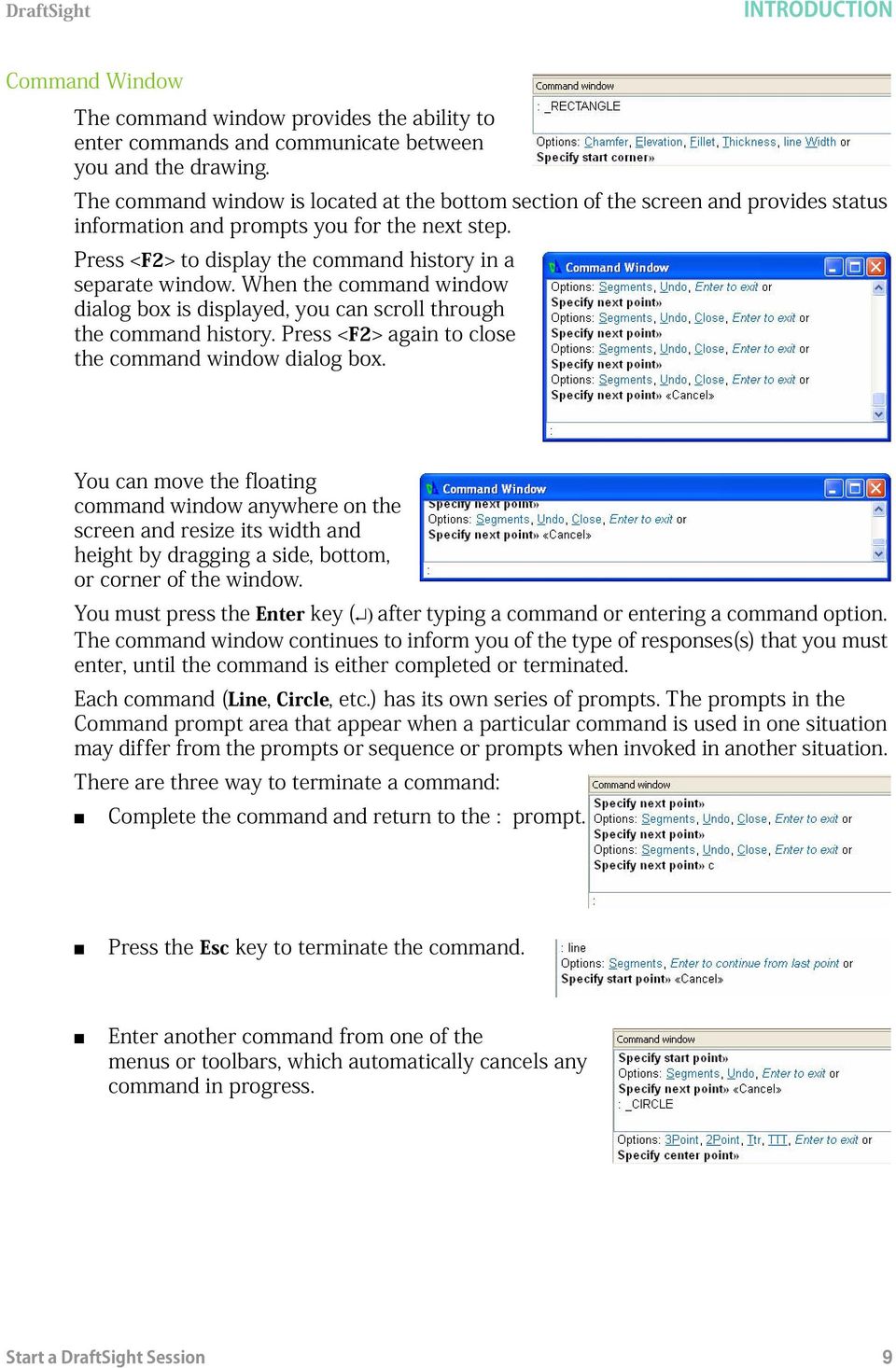
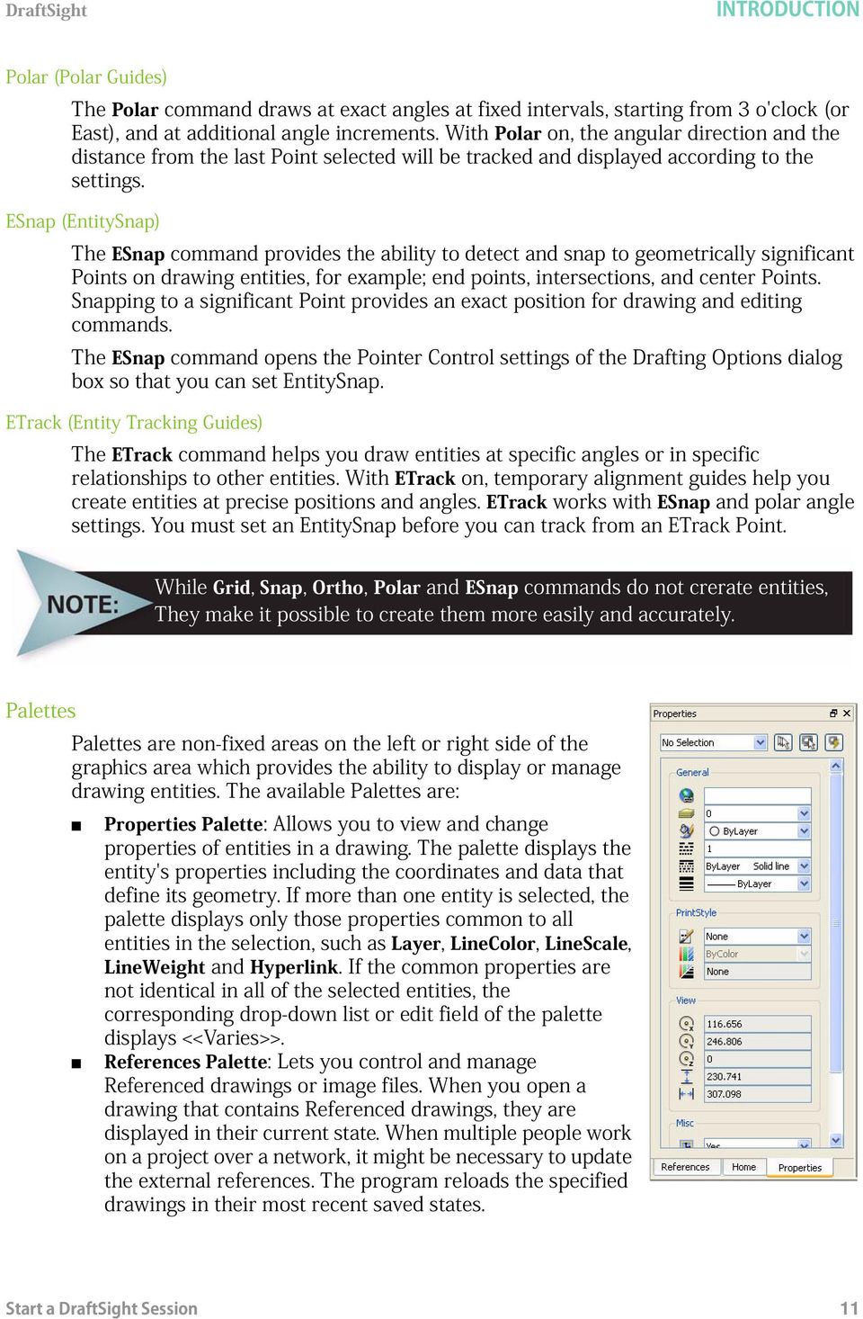
Part Number: PMT1080-ENG Rev. 1
|
|
|
- Stephen O’Brien’
- 10 years ago
- Views:
Transcription
1

2 2010 Dassault Systèmes, All Rights Reserved DraftSight and the DraftSight logos are trademarks of Dassault Systèmes or its subsidiaries in the US and/or other countries. Other brand or product names are trademarks or registered trademarks of their respective holders. The information and the software discussed in this document are subject to change without notice and are not commitments by Dassault Systemes or its subsidiaries. No material may be reproduced or transmitted in any form or by any means, electronic or mechanical, for any purpose without the express written permission of Dassault Systèmes or its subsidiaries. COMMERCIAL COMPUTER SOFTWARE - PROPRIETARY U.S. Government Restricted Rights. Use, duplication, or disclosure by the government is subject to restrictions as set forth in FAR (Commercial Computer Software - Restricted Rights), DFARS (Commercial Computer Software - Restricted Rights), DFARS (Commercial Computer Software and Commercial Computer Software Documentation), and in the license agreement, as applicable. Contractor/Manufacturer: Dassault Systèmes 10, rue Marcel Dassault Velizy-Villacoublay France The software discussed in this document is furnished under a license and may be used or copied only in accordance with the terms of this license. Nothing stated in, or implied by, this document or its contents shall be considered or deemed a modification or amendment of any warranties set forth in the terms of the software license agreement. Part Number: PMT1080-ENG Rev. 1

3 i
4 ii

5 iii
6 iv

7 v

8 DRAFTING APPLICATION vi

9 1

10 Convention Command prompt Meaning The steps in the lessons are numbered in sans serif bold. DraftSight commands and tools appear in this style. For example, Clicking the icon means choose the tool on the Draw toolbar. The symbol means press the key on the keyboard. Prompts and information in the command window and Command prompt are displayed in this font. For example: Specify next point» Information you type into the command window appears in this font. For example: Specify next point» Typewriter File names are in this font. For example, Lesson 1-1 2

11 NONAME_0.dwg 3

12 4
13 5 Cut Ctrl+C Copy :

14 6

15 7 : Specify option»
16 8

17 : 9
18 (Snap Grid) (Grid Display) (Orthogonal Drawing Mode) (Polar Guides) (EntitySnap) (Entity Tracking Guides) 10
 (Entity")
19 11
20 Zoom Center Zoom Dynamic Zoom Previous Zoom Selected Zoom Factor Zoom In Zoom Out Zoom Bounds Zoom Fit: 12

21 13 Line
22 Delete Move Pattern Rotate Scale Stretch Chamfer Fillet Split at Point Split 14
23 Weld Extend Trim Edit Hatch Display Order Edit PolyLine Explode Snap From 15
24 16 Layers PropertyManager :
25 ': This will undo previous changes made to layer settings. LineColor 17
26 18
27 Help 19
28 20
29 21
30 All ProgramsDassault Systemes DraftSight standard.dwt 22
31 23
32 Default: (0.00,0.00) Options: OFf, ON or Specify lower left corner» Default: (12.00,9.00) Specify upper right corner» 24
33 e 25
34 26
35 : Default: Dynamic Options: Bounds, Center, Dynamic, Fit, Previous, SElected, specify a scale factor (nx or nxp) or Specify first corner>> 27
36 Options: Segments or Specify start point>> Options: Segments, Undo, Enter to exit or Specify next point>> Options: Segments, Undo, Close, Enter to exit or Specify next point>> Options: Segments, Undo, Close, Enter to exit or Specify next point>> 28
37 Options: Segments, Undo, Close, Enter to exit or Specify next point>> Options: Segments, Undo, Close, Enter to exit or Specify next point>> Options: Segments, Undo, Close, Enter to exit or Specify next point>> Options: Segments, Undo, Close, Enter to exit or Specify next point>> Options: Segments, Undo, Close, Enter to exit or Specify next point>> 29
38 Options: Segments, Undo, Close, Enter to exit or Specify next point>> t Lesson
39 <Grid off> <Grid on> Lesson 1-1 Specify entities>> 1 found, 1 total 31
40 Specify entities>> Options: Center or Specify start point>> Specify center point>> 32
41 Specify start point>> Options: Angle, chord Length or Specify end point>> 33
42 Options: 3Point, 2Point, Ttr, TTT, Enter to exit or Specify center point>> Options: Diameter or Specify radius>> Lesson
43 35
44 Specify opposite corner: 36
45 Specify opposite corner: <Snap Off> 37
46 Specify entities>> 1 found, 2 total Specify entities>> Specify entities>> Specify opposite corner: 38
47 7 found, 7 total Specify entities» Default: Displacement: Specify from point>> Options: Enter from point as displacement or Specify destination>> Default: Displacement Options: Displacement or Specify from point>> 39
48 Options: Enter from point as displacement or Specify destination>> Nothing to undo. 40
49 standard.dwt dwt 41
50 42
51 Default: (0.00,0.00) Options: OFf, ON or Specify lower left corner» Default: (12.00,9.00) Specify upper right corner» 43
52 . 44
53 45
54 46
55 : Options: Segments or Specify start point>> Options: Segments, Undo, Enter to exit or Specify next point>> Options: Segments, Undo, Enter to exit or Specify next point>> Options: Segments, Undo, Enter to exit or Specify next point>> 47
56 Options: Segment or Specify Start point>> Options: Segments, Undo, Enter to exit or Specify next point>> Options: Segments, Undo, Enter to exit or Specify next point>> Options: Segments, Undo, Close, Enter to exit or Specify next point>> Options: Segments, Undo, Close, Enter to exit or Specify next point>> Lesson
57 Options: Segments or Specify Start point>> Options: Segments, Undo, Enter to exit or Specify next point>> Options: Segments, Undo, Close, Enter to exit or Specify next point>> Options: Segments, Undo, Close, Enter to exit or Specify next point>> Options: Segments, Undo, Close, Enter to exit or Specify next point>> Options: Segments, Undo, Close, Enter to exit or Specify next point>> 49
58 Options: Segments or Specify Start point>> Options: Segments, Undo, Enter to exit or Specify next point>> Options: Segments, Undo, Close, Enter to exit or Specify next point>> Options: Segments, Undo, Close, Enter to exit or Specify next point>> Options: Segments, Undo, Close, Enter to exit or Specify next point>> Options: Segments, Undo, Close, Enter to exit or Specify next point>> Options: Segments, Undo, Close, Enter to exit or Specify next point>> Options: Segments, Undo, Close, Enter to exit or Specify next point>> Options: Segments, Undo, Close, Enter to exit or Specify next point>> 50
59 Options: Segments, Undo, Close, Enter to exit or Specify next point>> Options: Segments, Undo, Close, Enter to exit or Specify next point>> Options: Segments, Undo, Close, Enter to exit or Specify next point>> Options: Segments, Undo, Close, Enter to exit or Specify next point>> Options: Segments, Undo, Close, Enter to exit or Specify next point>> 51
60 Sheet1Sheet2 52
61 sheet1 Sheet1 Sheet1 53
62 Select the button to return to the graphics area. 54
63 55
64 Nothing to undo 56
65 57
66 58
67 59 All ProgramsSolidWorks Corporation DraftSight standard.dwt template
68 Default: (0.00,0.00) Options: OFf, ON or Specify lower left corner» Default: (12.00,9.00) Specify upper right corner» Default: Dynamic Options: Bounds, Center, Dynamic, Fit, Previous, SElected, specify a scale factor (nx or nxp) or Specify first corner>> 60
69 61
70 Line 62
71 63
72 64
73 65
74 You can also click, from the Main Menu to display the dialog box. 66
75 67
76 inch.lin MM.LIN 68
77 inch.lin MM.LIN 69
78 Lesson
79 71
80 72
81 Options: 3Point, 2Point, Ttr, TTT Enter to exit or Specify center point» Option: Diameter or Specify radius» Default: 4 Enter number of Sides» Options: Side length or Specify center point» Default: COrner Options: COrner, or Side Specify distance option» Specify distance» 73
82 <Snap Off> Specify entities» 1 found, 1 total Specify entities» Default: Displacement Options: Displacement or Specify from point» Options: Enter to use first point as displacement or Specify second point» Default: Exit Options: Exit, Undo or Specify second point: 74
83 <Ortho On> Options: Segments or Specify start point» 75
84 Options: Segments, Undo Enter to exit or Specify next point» Options: Segments, Undo Enter to exit or Specify next point» : Options: Segments or Specify start point» Options: Segments, Undo Enter to exit or Specify next point» Options: Segments, Undo Enter to exit or Specify next point» 76
85 Specify cutting edges... Options: Enter to specify all entities or Specify entities» 1 found, 1 total Options: Enter to specify all entities or Specify entities» Options: Crossing, CRossline, Project, Edge, erase, Shift + select to extend or Specify segments to remove» Options: Crossing, CRossline, Project, Edge, erase, Shift + select to extend or Specify segments to remove» Options: Crossing, CRossline, Project, Edge, erase, Shift + select to extend or Specify segments to remove» 77
86 Options: Multiple, Polyline, Radius, Trim mode, Undo or Specify first entity» Default: 0.00 Specify radius» Options: Multiple, Polyline, Radius, Trim mode, Undo or Specify first entity» Options: Shift + select to apply corner or Specify second entity» Options: Multiple, Polyline, Radius, Trim mode, Undo or Specify first entity» 78
87 Options: Multiple, Polyline, Radius, Trim mode, Undo or Specify first entity» Specify entities» 79
88 7 found, 7 total Specify entities» Specify start point of mirror line» Specify end point of mirror line» Default: No Confirm: Delete source entities? Specify Yes, or No» Active positive angle in CCS: DIRECTION+counterclockwise BASE=0 Specify entities» 80
89 14 found, 14 total Specify entities» Specific pivot point» Default: 0 Options: Reference or Specify rotation angle»30 Specify cutting edges... Options: Enter to specify all entities or Specify entities» 1 found, 2 total 81
90 Options: Enter to specify all entities or Specify entities» Options: Crossing, CRossline, Project, Edge, erase, Undo, Shift + select to extend or Specify entity to remove» Specify entity to remove» Specify cutting edges... Options: Enter to specify all entities or Specify entities» 1 found, 2 total Options: Enter to specify all entities or Specify entities» Options: Crossing, CRossline, Project, Edge, erase, Undo, Shift + select to extend or Specify entity to remove» 82
91 Options: Segments or Specify start point» Options: Segments, Undo, Enter to exit or Specify next point» Options: Segments, Undo, Enter to exit or Specify next point» 83
92 Options: 3Point, 2Point, Ttr, TTT, Enter to exit or Specify center point» Options: Diameter or Specify radius» Specify diameter» Options: Chamfer,Elevation, Fillet, Thickness, line Width or Specify start corner» Options: Area, Dimensions, Rotation or Specify opposite corner» 84
93 85
94 Specify start fit point» Specify next fit point» 86
95 Options: Close, Fit tolerance, Enter for start tangent or Specify next fit point» Default: 0.00 Specify fit tolerance» Options: Close, Fit tolerance, Enter for start tangent or Specify next fit point» Options: Close, Fit tolerance, Enter for start tangent or Specify next fit point» Options: Close, Fit tolerance, Enter for start tangent or Specify next fit point» Specify tangency» 87
96 Options: Enter to continue from last point or Specify start point» Options: Arc, Halfwidth, Length, Undo, Width, Enter to exit or Specify next vertex» Options: Arc, Halfwidth, Length, Undo, Width, Enter to exit or Specify next vertex» Options: Arc, Halfwidth, Length, Undo, Width, Enter to exit or Specify next vertex» Options: Arc, Halfwidth, Length, Undo, Width, Enter to exit or Specify next vertex» Options: Arc, Halfwidth, Length, Undo, Width, Enter to exit or Specify next vertex» Options: Arc, Halfwidth, Length, Undo, Width, Enter to exit or Specify next vertex» Options: Arc, Halfwidth, Length, Undo, Width, Enter to exit or Specify next vertex» Options: Arc, Halfwidth, Length, Undo, Width, Enter to exit or Specify next vertex» 88
97 Options: Arc, Halfwidth, Length, Undo, Width, Enter to exit or Specify next vertex» Options: Arc, Halfwidth, Length, Undo, Width, Enter to exit or Specify next vertex» Options: Arc, Halfwidth, Length, Undo, Width, Enter to exit or Specify next vertex» Options: Arc, Halfwidth, Length, Undo, Width, Enter to exit or Specify next vertex» Options: Arc, Halfwidth, Length, Undo, Width, Enter to exit or Specify next vertex» OOptions: Arc, Halfwidth, Length, Undo, Width, Enter to exit or Specify next vertex 89
98 Options: Multiple or Specify polyline» Options: Decurve, Edit vertex, Fit, Join, Lengthen, Open, Spline, Undo, Width, or exit Specify option» Specify new width» Options: Decurve, Edit vertex, Fit, Join, Lengthen, Open, Spline, Undo, Width, or exit Specify option» 90
99 91
100 standard.dwt 92
101 Default: (0.00,0.00) Options: OFf, ON or Specify lower left corner» Default: (12.00,9.00) Specify upper right corner» Select Lesson
102 94
103 inch.lin MM.LIN 95
104 inch.lin 96
105 MM.LIN 97
106 98
107 Options: Chamfer, Elevation, Fillet, Thickness, line Width or Specify start corner» Options: Area, Dimensions, Rotation or Specify opposite corner» 99
108 Options: 3Point, 2Point, Ttr, TTT, Enter to exit or Specify center point» Options: Diameter or Specify radius» <Snap Off> 1 found, 1 total» 100
109 (TRIM mode) Active chamfer Dist1 = 0.00, Dist2 = 0.00 Options: Angle, Distance, method, Multiple, Polyline, Trim mode, Undo or Specify first line» Default:0.00 Specify first distance: Default: Specify second distance: Options: Angle, Distance, method, Multiple, Polyline, Trim mode, Undo or Specify first line» Options: Angle, Distance, method, Multiple, Polyline, Trim mode, Undo or Specify first line» Options: Shift+ select to apply corner or Specify second line 101
110 ptions: Angle, Distance, method, Multiple, Polyline, Trim mode, Undo or Specify first line» Options: 3Point, 2Point, Ttr, TTT, Enter to exit or Specify center point» Default: 5.00 Options: Diameter or Specify radius» Options: 3Point, 2Point, Ttr, TTT, Enter to exit or Specify center point» Default: Options: Diameter or Specify radius» 102
111 1 found, 1 total Specify entities» 103
112 104
113 standard.dwt Default: (0.00,0.00) Options: OFf, ON or Specify lower left corner» Default: (12.00,9.00) Specify upper right corner» 105
114 Select Lesson
115 inch.lin MM.LIN PHANTOM 107
116 Options: 3Point, 2Point, Ttr, TTT, Enter to exit or Specify center point» Options: Diameter or Specify radius» : Options: 3Point, 2Point, Ttr, TTT, Enter to exit or Specify center point» Options: Diameter or Specify radius» 108
117 : Options: 3Point, 2Point, Ttr, TTT, Enter to exit or Specify center point» Specify first tangency» <Snap Off> Specify first tangency» Default: Specify radius» : Options: 3Point, 2Point, Ttr, TTT, Enter to exit or Specify center point» Specify first tangency» Specify second tangency» Default: Specify radius» Specify cutting edges... Options: Enter to specify all entities or 109
118 Specify entities» Options: Crossing, CRossline, Project, Edge, erase, Undo, Shift + select to extend or Specify segments to remove» Options: Crossing, CRossline, Project, Edge, erase, Undo, Shift + select to extend or Specify segments to remove» Options: Crossing, CRossline, Project, Edge, erase, Undo, Shift + select to extend or Specify segments to remove» Default: 1.00 Options: Delete, Distance, destination Layer, Through point or Specify distance» 110
119 Default: Exit, Options: Exit, Undo or Specify source entity» Default: Exit Options: Both sides, Exit, Multiple, Undo or Specify side for destination» Default: Exit, Options: Exit, Undo or Specify source entity» Default: Exit Options: Both sides, Exit, Multiple, Undo or Specify side for destination» Specify source entity» Specify cutting edges... Options: Enter to specify all entities or Specify entities» 1 found, 1 total Options: Enter to specify all entities or Specify entities» 111
120 1 found, 2 total Options: Enter to specify all entities or Specify entities» Options: Crossing, CRossline, Project, Edge, erase, Undo, Shift + select to extend or Specify segments to remove» Options: Crossing, CRossline, Project, Edge, erase, Undo, Shift + select to extend or Specify segments to remove» Options: Crossing, CRossline, Project, Edge, erase, Undo, Shift + select to extend or Specify segments to remove» 112
121 Specify entities» 6 found, 6 total» Specify entities» Specify pattern center point» 113
122 114
123 115
124 Lesson 1-3). Lesson
125 Lesson 2-2) 117
126 All ProgramsDassault SystemesDraftSight 118
127 119
128 120
129 121
130 Lesson 2-3 Lesson
131 123
132 124
133 Default: Entity Options: Entity or Specify first extension line position» Specify second extension line position» Options: Angle, Horizontal, Note, Rotated, Text, Vertical or Specify Dimension line position» 125
134 : Default: Entity Options: Entity or Specify first extension line position» Specify entity» Options: Angle, Horizontal, Note, Rotated, Text, Vertical or Specify Dimension Line position» 126
135 127
136 Options: Enter to specify vertex or Specify entity» <Snap Off> Specify second line» Options: Angle, Note, Text or Specify dimension position» 128
137 Default: Entity Options: Entity or Specify first extension line position» Specify second extension line position» Options: Angle, Note, Text or Specify dimension line position» 129
138 Oblique) Default: Home options: Angle, Home, New, Oblique or Specify option» Specify new Dimension Text: Specify dimension(s)» 130
139 1 found, 1 total Specify dimension(s)» <ESnaps On>. Specify start point» 131
140 Specify end point» Distance = 50.00, Angle in XY Plane = 300, Angle from XY Plane = 0 Delta X = 25.00, Delta Y = , Delta Z = 0.00 Specify dimension» Default: (174.29,101.34,0.00) Options: Angle, Center, Home, Left, Right or Specify new text position» Specify angle for Dimension Text: 132
141 Specify entities» 1 found, 7 total Select entities» Default: Displacement Options: Displacement or Specify from point: Options: Enter to use from point as displacement or Specify destination» 133
142 <Snap On> <ESnaps On> <Ortho On> : : Default: World Options: align to Entity, NAmed, Previous, View, World, X, Y, Z, ZAxis or Specify origin» Option: Enter to accept or Specify X-axis through point» 134
143 Snap Off Ortho on Specify datum position» options: Angle, Note, Text, X datum, Y datum or Specify dimension position» 135
144 Dimension Text: 0.00 Options: Select dimension, Undo or Specify feature position» Options: Select dimension, Undo or Specify feature position» Specify dimension» Lesson
145 Lesson 2-2 Lesson
146 138
147 Specify curved entity» : Specify curved entity» : Specify curved entity» : Specify curved entity» Specify curved entity» Specify curved entity» 139
148 Select entities» Select entities» Select entities» Specify pattern center point» 140
149 Pattern Axis point X: Axis point Y: Specify curved entity» 141
150 Options: Angle, Note, Text or Specify dimension position» 142
151 143
152 144
153 DRAFTING APPLICATION 145
154 DRAFTING APPLICATION 146
155 DRAFTING APPLICATION 147
156 DRAFTING APPLICATION 148
157 DRAFTING APPLICATION All ProgramsDassault SystemesDraftSight. standard.dwt 149
158 DRAFTING APPLICATION Default: (0.00,0.00) Options: OFf, ON or Specify lower left corner» Default: (12.00,9.00) Specify upper right corner» 150
159 DRAFTING APPLICATION Lesson
160 DRAFTING APPLICATION Options: Segments, or Specify start point>> Options: Segments, Undo, Enter to exit or Specify next point>> Options: Segments, Enter to continue from last point or 152
161 DRAFTING APPLICATION Specify start point>> Options: Segments, Undo, Enter to exit or Specify next point>> : Options: Segments, Enter to continue from last point or Specify start point>> Options: Segments, Undo, Enter to exit or Specify next point>> : Options: Segments, Enter to continue from last point or Specify start point>> Options: Segments, Undo, Enter to exit or Specify next point>> Active TextStyle: Standard Text height: 0.20 Specify first corner>> 153
162 DRAFTING APPLICATION Options: Angle, Height, Justify, Line spacing, textstyle, Width or Specify opposite corner>> default: 0.20 Specify text height>> Options: Angle, Height, Justify, Line spacing, textstyle, Width or Specify opposite corner>>100,20 Specify entities>> 154
163 DRAFTING APPLICATION Specify entities>> Specify insertion base point>> 155
164 DRAFTING APPLICATION : <Snap Off> Options: Segments, Enter to continue from last point or Specify start point>> 156
165 DRAFTING APPLICATION Options: Segments, Undo or Enter to exit or Specify next point>> Options: Segments, Undo or Enter to exit or Specify next point>> : Options: Segments, Enter to continue from last point or Specify start point>> Options: Segments, Undo or Enter to exit or Specify next point>> Options: Segments, Undo or Enter to exit or Specify next point>> Options: Segments, Enter to continue from last point or Specify start point>> 157
166 DRAFTING APPLICATION Options: Segments, Undo or Specify next point>> : Options: Segments, Enter to continue from last point or Specify start point>> Options: Segments, Undo or Specify next point>> : Options: Segments, Enter to continue from last point or Specify start point>> Options: Segments, Undo or Specify next point>> : Options: Segments, Enter to continue from last point or Specify start point>> Options: Segments, Undo or Specify next point>> 158
167 DRAFTING APPLICATION Specify entities>> Specify entities>> Specify insertion base point>> 159
168 DRAFTING APPLICATION : Ring Default: 0.50 Specify inside diameter>> Default: 1.00 Specify outside diameter>> 160
169 DRAFTING APPLICATION Default: exit Specify position>> Default: exit Specify position>> Specify entities>> 1 found, 1 total Specify entities>> 161
170 DRAFTING APPLICATION standard.dwt 162
171 DRAFTING APPLICATION Default: (0.00,0.00) Options: OFf, ON or Specify lower left corner» Default: (12.00,9.00) Specify upper right corner» 163
172 DRAFTING APPLICATION Lesson 4-2 Options: Angle, angle Bisect, Horizontal, Offset, Vertical, Enter to exit or Specify position» 164
173 DRAFTING APPLICATION Options: Enter to exit or Specify next point» Options: Enter to exit or Specify next point» Options: Enter to exit or Specify next point» Options: Enter to exit or Specify next point» Options: Enter to exit or Specify next point» Options: Enter to exit or Specify next point» Options: Enter to exit or Specify next point» 165
174 DRAFTING APPLICATION Options: Angle, angle Bisect, Horizontal, Offset, Vertical, Enter to exit or Specify position» Options: Enter to exit or Specify next point» Options: Enter to exit or Specify next point» Options: Enter to exit or Specify next point» Options: Enter to exit or Specify next point» Options: Enter to exit or Specify next point» Options: Enter to exit or Specify next point» Options: Enter to exit or Specify next point» Options: Enter to exit or Specify next point» 166
175 DRAFTING APPLICATION 167
176 DRAFTING APPLICATION Options: Segments, Enter to continue from last point or Specify start point» Options: Segments, Undo, Enter to exit or Specify next point» Options: Segments, Undo, Enter to exit or Specify next point» Options: Segments, Undo, Enter to exit or Specify next point» Options: Segments, Undo, Enter to exit or Specify next point» Options: Segments, Undo, Enter to exit or Specify next point» Options: Segments, Undo, Enter to exit or Specify next point» Options: Segments, Enter to continue from last point or Specify start point» Options: Segments, Undo, Enter to exit or Specify next point» Options: Segments, Undo, Enter to exit or Specify next point» 168
177 DRAFTING APPLICATION Options: Segments, Undo, Enter to exit or Specify next point» Options: Segments, Undo, Enter to exit or Specify next point» Options: Segments, Enter to continue from last point or Specify start point» Options: Segments, Undo, Enter to exit or Specify next point» Options: Segments, Enter to continue from last point or Specify start point» Options: Segments, Undo, Enter to exit or Specify next point» Options: Segments, Undo, Enter to exit or Specify next point» Options: Segments, Undo, Enter to exit or Specify next point» Options: Segments, Undo, Enter to exit or Specify next point» 169
178 DRAFTING APPLICATION Options: Segments, Enter to continue from last point or Specify start point» Options: Segments, Undo, Enter to exit or Specify next point» Options: 3Point, 2Point, Ttr, TTT, Enter to exit or Specify Center point» Options: Diameter or Specify Radius» Options: Segments, Enter to continue from last point or Specify start point» Options: Segments, Undo, Enter to exit or Specify next point» 170
179 DRAFTING APPLICATION Options: Segments, Enter to continue from last point or Specify start point» Options: Segments, Enter to continue from last point or Specify start point» Options: Segments, Enter to continue from last point or Specify start point» Options: Segments, Undo, Enter to exit or Specify next point» Options: Segments, Enter to continue from last point or Specify start point» Options: Segments, Undo, Enter to exit or Specify next point» 171
180 DRAFTING APPLICATION Options: Deselect boundary, Entities or 172
181 DRAFTING APPLICATION Specify internal point» Options: Deselect boundary, Entities or Specify internal point» 173
182 DRAFTING APPLICATION. Default: Entity Options: Entity or Specify first extension line position» Specify second extension line position» 174
183 DRAFTING APPLICATION Options: Angle, Horizontal, Note, Rotated, Text, Vertical or Specify dimension Line position» : : Default: Entity Options: Entity or Specify first extension line position» Specify second extension line position» Options: Angle, Horizontal, Note, Rotated, Text, Vertical or Specify dimension Line position» 175
184 DRAFTING APPLICATION 176
185 DRAFTING APPLICATION 177
186 DRAFTING APPLICATION 178
SpaceClaim Introduction Training Session. A SpaceClaim Support Document
 SpaceClaim Introduction Training Session A SpaceClaim Support Document In this class we will walk through the basic tools used to create and modify models in SpaceClaim. Introduction We will focus on:
Introduction to CATIA V5
 Introduction to CATIA V5 Release 16 (A Hands-On Tutorial Approach) Kirstie Plantenberg University of Detroit Mercy SDC PUBLICATIONS Schroff Development Corporation www.schroff.com www.schroff-europe.com
This is a preview of the book "QCAD - An Introduction to Computer-Aided Design (CAD)" QCAD. An Introduction to ComputerAided Design (CAD)
 QCAD. An Introduction to ComputerAided Design (CAD)") QCAD An Introduction to ComputerAided Design (CAD) Andrew Mustun Table of Contents Introduction Part I: First Steps with QCAD Introducing the QCAD Application 8 15 16 The First Start 16 The Application
QCAD An Introduction to ComputerAided Design (CAD) Andrew Mustun Table of Contents Introduction Part I: First Steps with QCAD Introducing the QCAD Application 8 15 16 The First Start 16 The Application
Basic AutoSketch Manual
 Basic AutoSketch Manual Instruction for students Skf-Manual.doc of 3 Contents BASIC AUTOSKETCH MANUAL... INSTRUCTION FOR STUDENTS... BASIC AUTOSKETCH INSTRUCTION... 3 SCREEN LAYOUT... 3 MENU BAR... 3 FILE
TABLE OF CONTENTS. INTRODUCTION... 5 Advance Concrete... 5 Where to find information?... 6 INSTALLATION... 7 STARTING ADVANCE CONCRETE...
 Starting Guide TABLE OF CONTENTS INTRODUCTION... 5 Advance Concrete... 5 Where to find information?... 6 INSTALLATION... 7 STARTING ADVANCE CONCRETE... 7 ADVANCE CONCRETE USER INTERFACE... 7 Other important
 Edinburgh COLLEGE of ART ARCHITECTURE 3D Modelling in AutoCAD - tutorial exercise The screen The graphics area This is the part of the screen in which the drawing will be created. The command prompt area
Introduction to AutoCAD lar 543 spring 2008
 Introduction to AutoCAD lar 543 spring 2008 for landscape architects Makie Suzuki, Chihiro Shinohara in this session we cover: - introduction - basic operation - basic drawing tools - basic editing In
Getting Started With DraftSight A Guide For AEC Users
 Getting Started With DraftSight A Guide For AEC Users DraftSight.com Facebook.com/DraftSight Welcome to DraftSight a valuable tool for any AEC professional! DraftSight is more than a free, professional-grade
Pro/ENGINEER Wildfire 4.0 Basic Design
 Introduction Datum features are non-solid features used during the construction of other features. The most common datum features include planes, axes, coordinate systems, and curves. Datum features do
Chapter 9. Editing Features. Learning Objectives
 Chapter 9 Editing Features Learning Objectives After completing this chapter, you will be able to: Edit features. Edit sketches of the sketch based features. Edit the sketch plane of the sketch based features.
2013 Getting Started Guide
 2013 Getting Started Guide The contents of this guide and accompanying exercises were originally created by Nemetschek Vectorworks, Inc. Vectorworks Fundamentals Getting Started Guide Created using: Vectorworks
AutoCAD Workbook 3D DRA 54 Hartnell College Engineering Technology Parviz D. Entekhabi
 AutoCAD Workbook 3D AutoCAD Workbook 3D DRA 54 Hartnell College Engineering Technology Parviz D. Entekhabi 1 Lesson 01 Creating a Basic 3D Surface Model Elevation & Thickness AutoCAD Workbook 3D To work
AutoCAD Structural Detailing 2011. Getting Started with AutoCAD Structural Detailing, Reinforcement module
 AutoCAD Structural Detailing 2011 Getting Started with AutoCAD Structural Detailing, Reinforcement module 2010 Autodesk, Inc. All Rights Reserved. Except as otherwise permitted by Autodesk, Inc., this
Datum > Curve KIM,ME,NIU
 Datum > Curve Intersect First create at least one quilt on the surface of the model. Feature > Surface (> New) > Copy (do not use offset that creates a surface off the solid surface even with zero offset)
SDC. Schroff Development Corporation WWW.SDCACAD.COM PUBLICATIONS. MultiMedia CD by Jack Zecher
 MultiMedia CD by Jack Zecher An audioi/visual presentation of the tutorial exercises SDC PUBLICATIONS Schroff Development Corporation WWW.SDCACAD.COM AutoCAD 2002 Tutorial 2-1 Lesson 2 Geometric Construction
CATIA Drafting TABLE OF CONTENTS
 TABLE OF CONTENTS Introduction...1 Drafting...2 Drawing Screen...3 Pull-down Menus...4 File...4 Edit...5 View...6 Insert...7 Tools...8 Drafting Workbench...9 Views and Sheets...9 Dimensions and Annotations...10
Drawing a Bedroom Floorplan
 Appendix A Drawing a Bedroom Floorplan In this chapter, you will learn the following to World Class standards: Draw a Bedroom Floorplan Draw the Bedroom Walls Draw and Dimension the Bedroom Door Draw and
Understand the Sketcher workbench of CATIA V5.
 Chapter 1 Drawing Sketches in Learning Objectives the Sketcher Workbench-I After completing this chapter you will be able to: Understand the Sketcher workbench of CATIA V5. Start a new file in the Part
AutoCAD Civil 3D 2010 ESSENTIALS
 AutoCAD Civil 3D 2010 ESSENTIALS SDC PUBLICATIONS Schroff Development Corporation www.schroff.com Better Textbooks. Lower Prices. Visit our website to learn more about this and other books: AutoCAD Civil
Introduction to Autodesk Inventor for F1 in Schools
 Introduction to Autodesk Inventor for F1 in Schools F1 in Schools Race Car In this course you will be introduced to Autodesk Inventor, which is the centerpiece of Autodesk s digital prototyping strategy
SolidWorks Implementation Guides. Sketching Concepts
 SolidWorks Implementation Guides Sketching Concepts Sketching in SolidWorks is the basis for creating features. Features are the basis for creating parts, which can be put together into assemblies. Sketch
Chapter 1. Creating Sketches in. the Sketch Mode-I. Evaluation chapter. Logon to www.cadcim.com for more details. Learning Objectives
 Chapter 1 Creating Sketches in Learning Objectives the Sketch Mode-I After completing this chapter you will be able to: Use various tools to create a geometry. Dimension a sketch. Apply constraints to
What s New V 11. Preferences: Parameters: Layout/ Modifications: Reverse mouse scroll wheel zoom direction
 What s New V 11 Preferences: Reverse mouse scroll wheel zoom direction Assign mouse scroll wheel Middle Button as Fine tune Pricing Method (Manufacturing/Design) Display- Display Long Name Parameters:
Creating Drawings in Pro/ENGINEER
 6 Creating Drawings in Pro/ENGINEER This chapter shows you how to bring the cell phone models and the assembly you ve created into the Pro/ENGINEER Drawing mode to create a drawing. A mechanical drawing
Tutorial - First Level: 2D Fundamentals
 AutoCAD 2013 Prepares you for the Autodesk Certified Associate Exam Tutorial - First Level: 2D Fundamentals Randy H. Shih Multimedia DVD SDC PUBLICATIONS Schroff Development Corporation Better Textbooks.
Basic 2D Design Be sure you have the latest information!
 Basic 2D Design mastercam x getting started tutorials Basic 2D Design December 2011 Be sure you have the latest information! Information might have been changed or added since this document was published.
Pro/ENGINEER Wildfire 5.0 Introduction to Surface Modeling
 Introduction Several advanced surface types are available as listed below. Variable Section Sweep Boundary Blend Section to Surfaces Blend Surface to Surface Blend A surface is created by sweeping a single
Computer-Aided Drafting I
 Course Syllabus Computer-Aided Drafting I Course Description This course introduces computer-aided drafting (CAD) and examines the hardware that makes up a CAD workstation. It also covers the operating
SAVEAS Saves the current drawing using a new file name, opens the newly named file and closes the drawing with the old name.
 That CAD Girl J ennifer dib ona Website: www.thatcadgirl.com Email: [email protected] Phone: (919) 417-8351 Fax: (919) 573-0351 Introduction to Autocad and IntelliCAD Command List This document
SolidWorks. SolidWorks Teacher Guide. and Student Courseware
 SolidWorks SolidWorks Teacher Guide and Student Courseware SolidWorks Corporation Outside the U.S.: +1-978-371-5011 300 Baker Avenue Fax: +1-978-371-7303 Concord, Massachusetts 01742 USA Email: [email protected]
Introduction to Autodesk Inventor for F1 in Schools
 F1 in Schools race car Introduction to Autodesk Inventor for F1 in Schools In this course you will be introduced to Autodesk Inventor, which is the centerpiece of Autodesk s Digital Prototyping strategy
ZW3D CAD Fundamentals Training Guide
 ZW3D CAD Fundamentals Training Guide ZW3D Specialized End-to-End Solutions Copyright and Trademarks Copyright 2010 ZwCAD Software Co., Ltd. All rights reserved. Floor 4, NO.886, Tianhe North Road, Guangzhou
Generative Drafting. Page 1 1997 2001 DASSAULT SYSTEMES. IBM Product Lifecycle Management Solutions / Dassault Systemes
 Generative Drafting Page 1 Tutorial Objectives Description This Tutorial is an introduction to Generative Drafting. Message To show how CATIA V5 allows the user to automatically generate associative drafting
Chapter 23: Drafting in Worksheet View
 Chapter 23: Drafting in Worksheet View Worksheet View is a powerful, 2D production drafting module. Here you can find all of the drawing and editing tools needed to create fast, accurate, detailed working
Tutorial: 3D Pipe Junction Using Hexa Meshing
 Tutorial: 3D Pipe Junction Using Hexa Meshing Introduction In this tutorial, you will generate a mesh for a three-dimensional pipe junction. After checking the quality of the first mesh, you will create
SketchUp Instructions
 SketchUp Instructions Every architect needs to know how to use SketchUp! SketchUp is free from Google just Google it and download to your computer. You can do just about anything with it, but it is especially
Layout Tutorial. Getting Started
 Getting Started Layout Tutorial This tutorial will explain how create a layout template, send views to a layout page, then save the document in PDF format. In this tutorial you will learn about: Creating
First Level: 2D Fundamentals. by Randy H. Shih Oregon Institute of Technology
 AutoCAD 2008 Tutorial First Level: 2D Fundamentals by Randy H. Shih Oregon Institute of Technology MultiMedia CD by Jack Zecher Indiana University Purdue University Indianapolis SDC PUBLICATIONS Schroff
Sketcher. Preface What's New? Getting Started Basic Tasks Customizing Workbench Description Glossary Index
 Sketcher Preface What's New? Getting Started Basic Tasks Customizing Workbench Description Glossary Index Dassault Systèmes 1994-99. All rights reserved. Preface CATIA Version 5 Sketcher application makes
Bentley MicroStation V8i
 Bentley MicroStation V8i Bentley MicroStation V8i is a CAD program designed with the interoperability of software in mind. MicroStation is compatible with both DWG and DGN files, either preexisting or
Assignment 3 Floor Plan CAD Fundamentals I Due February 1 Architecture 411
 Due February 1 Architecture 411 Objective To learn to draft precise architectural plan drawings. To gain experience with CAD drafting tools and techniques. Exercise 1. Come up with a floor plan for a residence
CATIA Wireframe & Surfaces TABLE OF CONTENTS
 TABLE OF CONTENTS Introduction... 1 Wireframe & Surfaces... 2 Pull Down Menus... 3 Edit... 3 Insert... 4 Tools... 6 Generative Shape Design Workbench... 7 Bottom Toolbar... 9 Tools... 9 Analysis... 10
To draw a line. To create a construction line by specifying two points
 Drawing Lines, Polygons and Rectangles The line is the basic object in AutoCAD. You can create a variety of lines: single lines, multiple line segments with and without arcs, multiple parallel lines, and
Importing and Opening an Alignment
 Chapter 6 Alignment Files An alignment defines the route of a road, utility line, water way, etc., and is typically comprised of both horizontal and vertical elements. Also, an alignment may include cross-sectional
4 Manipulating Elements
 4 Manipulating Elements In the context of this course, Manipulation of elements means moving, copying, rotating, scaling and some other similar operations. We will find that manipulations are always a
TurboCAD Pro V21 - Architectural Presentation
 TurboCAD Pro V21 - Architectural Presentation From 2D Drawing to 3D Model Donald B. Cheke 1 Copyright 2014 Donald B. Cheke TurboCAD is a registered trademark of IMSI/Design Published by: Donald B. Cheke
Get-Snap. Once you have installed the DataCAD 9.03 update, you are ready to take advantage of this new feature.
 DATACAD LLC TECHNICAL BULLETIN Software for Architecture Get-Snap (For DataCAD 9.03 and later) The new Get-Snap feature allows you to input distances relative to other objects in the drawing. This allows
Wireframe and Surface
 Wireframe and Surface Preface What's New Getting Started Basic Tasks Workbench Description Glossary Index Dassault Systèmes 1994-99. All rights reserved. Preface CATIA Version 5 Wireframe and Surface allows
AutoCAD 2009. New Icon Quick Reference
 AutoCAD 2009 New Quick Reference Contents Chapter 1 New Quick Reference..................... 1 Toolbars................................... 1 3D Navigation Toolbar........................ 1 CAD Standards
Software User's Guide
 Software User's Guide Brother QL-series The contents of this guide and the specifications of this product are subject to change without notice. Brother reserves the right to make changes without notice
10.0-2. Finite Element Modeling
 What s New in FEMAP FEMAP 10.0 and 10.0.1 include enhancements and new features in: User Interface on page 3 Meshing on page 23 Mesh Associativity on page 33 Properties on page 33 Functions on page 35
SpaceClaim 2012 Release Notes. SpaceClaim 2012. Release Notes. Page 1. www.spaceclaim.com
 SpaceClaim 2012 Release Notes Page 1 Table of Contents Table of Contents... 2 SpaceClaim 2012 Enhancements Overview... 3 Model Preparation... 3 Interoperability... 3 Modeling... 3 Detailing... 3 Sheet
How To Create A View Frame In 3D
 12/4/2008-10:00 am - 11:30 am Room:Palazzo O-P (5th) The Secrets of Cutting Plan and Profile Sheets in AutoCAD Civil 3D Michelle Rasmussen - Application Engineer, IMAGINiT Technologies CV304-1P In this
Drawing a little mechanical part using LibreCAD
 TUTORIAL Drawing a little mechanical part using LibreCAD Tutorial by Claudio Guarnieri CLAUDIO GUARNIERI: Drawing a little mechanical part using LibreCAD Page 1 of 17 Introduction Hello everyone! This
Interactive Voting System. www.ivsystem.nl. IVS-Basic IVS-Professional 4.4
 Interactive Voting System www.ivsystem.nl IVS-Basic IVS-Professional 4.4 Manual IVS-Basic 4.4 IVS-Professional 4.4 1213 Interactive Voting System The Interactive Voting System (IVS ) is an interactive
WORKING DRAWINGS Shaft Support Subassembly
 Start Autocad and open a NEW drawing WORKING DRAWINGS Shaft Support Subassembly Set up the layers and line types using the LAYER command Draw the following parts and save them each in a separate file BEARING
SolidWorks Tutorial 5
 SolidWorks Tutorial 5 Tic-Tac-Toe Preparatory Vocational Training and Advanced Vocational Training Dassault Systèmes SolidWorks Corporation, 75 Wyman Street Waltham, Massachusetts 05 USA Phone: +-800-69-9000
User's Guide. DeltaCad. Professional for Windows VERSION 8.0
 User's Guide DeltaCad Professional for Windows VERSION 8.0 By Midnight Software, Inc. Copyright 1995-2013 by M idnight Software, Inc. All rights reserved. The contents of this manual are subject to copyright
Creating a 2D Geometry Model
 Creating a 2D Geometry Model This section describes how to build a 2D cross section of a heat sink and introduces 2D geometry operations in COMSOL. At this time, you do not model the physics that describe
K e y b o a r d s h o rt c ut s
 Keyboard shortcuts Mouse navigation Middle button (wheel) Click + drag = pan Double-click = re-center view Left button Click = tool operation Click + spacebar = pan Shift + click + drag = multi-select
If you know exactly how you want your business forms to look and don t mind detail
 Advanced Form Customization APPENDIX E If you know exactly how you want your business forms to look and don t mind detail work, you can customize QuickBooks forms however you want. With QuickBooks Layout
OBJECTIVES. Computeraided. Drafting and Design. Drafting vocabulary
 This sample chapter is for review purposes only. Copyright The Goodheart-Willcox Co., Inc. All rights reserved. 50 Exploring Drafting Chapter 7 Computer-Aided Drafting and Design 5 7 Computer-Aided Drafting
Advanced Surface Modeling
 This sample chapter is for review purposes only. Copyright The Goodheart-Willcox Co., Inc. ll rights reserved. Chapter dvanced Modeling Learning Objectives fter completing this chapter, you will be able
PRACTICAS DE AUTOCAD LIMAC 1 PRACTICE CHAIR
 PRACTICAS DE AUTOCAD LIMAC 1 PRACTICE CHAIR PRACTICAS DE AUTOCAD LIMAC 2 Setting Up for 3D Entiles Make or verify the setting shown in the chair drawing settings thable Command: VPOINT enter a view point
Interactive Drafting
 Interactive Drafting Preface What's New Getting Started Basic Tasks Advanced Tasks Workbench Description Customizing Glossary Index Dassault Systèmes 1994-99. All rights reserved. Preface CATIA Version
Tutorial. IMPORTING AND EXPORTING AutoCAD FILES (DWG)
") In addition to Canvas numerous import and export capabilities, you can also import AutoCAD 2007 files into Canvas 11, edit them, and export to PDF format. Objectives After this exercise you will be able
In addition to Canvas numerous import and export capabilities, you can also import AutoCAD 2007 files into Canvas 11, edit them, and export to PDF format. Objectives After this exercise you will be able
Part Design. Preface What's New? Getting Started Basic Tasks Advanced Tasks Workbench Description Customizing Glossary Index
 Part Design Preface What's New? Getting Started Basic Tasks Advanced Tasks Workbench Description Customizing Glossary Index Dassault Systèmes 1994-99. All rights reserved. Preface The CATIA Version 5 Part
Torchmate CAD User s Guide
 Torchmate CAD User s Guide Revised May 2011 Table of Contents: Overview of the Manual Installation and Setup Important Configuration Changes Overview of Menus Navigation and Selection Methods Basic CAD
Proprietary and restricted rights notice
 Proprietary and restricted rights notice This software and related documentation are proprietary to Siemens Product Lifecycle Management Software Inc. 2012 Siemens Product Lifecycle Management Software
Practice Workbook. QuickStart for Roadway Modeling Using OpenRoads
 Practice Workbook This workbook is designed for use in Live instructor-led training and for OnDemand selfstudy. The explanations and demonstrations are provided by the instructor in the classroom, or in
Contents. Introduction... 4
 Copyright 2014 Idea Spectrum, Inc. All Rights Reserved. Realtime Landscaping Architect, the Realtime Landscaping Architect logo, Idea Spectrum, and the Idea Spectrum logo are all trademarks of Idea Spectrum,
Castle Modeling. In this PDF tutorial we will be modeling a simple castle as pictured above.
 Course: 3D Design Title: Castle Modeling Blender: Version 2.6X Level: Beginning Author; Neal Hirsig ([email protected]) May, 2012 This tutorial assumes that you already know how to: Display orthographic
Lesson Four 3D Modeling
 Lesson Four 3D Modeling In this lesson you will learn how to: Easily Rotate the UCS to model in different planes Model lines in a method similar to drawing isometrics Create 3D Router Lines Automatically
10. THERM DRAWING TIPS
 10. THERM DRAWING TIPS 10.1. Drawing Tips The THERM User's Manual describes in detail how to draw cross-sections in THERM. This section of the NFRC Simualation Training Manual presents some additional
Structure Design. Preface What's New? Getting Started Basic Tasks Advanced Tasks Workbench Description Customizing Glossary Index
 Structure Design Preface What's New? Getting Started Basic Tasks Advanced Tasks Workbench Description Customizing Glossary Index Dassault Systèmes 1994-2000. All rights reserved. Preface CATIA Version
Course Project Lab 3 - Creating a Logo (Illustrator)
") Course Project Lab 3 - Creating a Logo (Illustrator) In this lab you will learn to use Adobe Illustrator to create a vector-based design logo. 1. Start Illustrator. Open the lizard.ai file via the File>Open
Course Project Lab 3 - Creating a Logo (Illustrator) In this lab you will learn to use Adobe Illustrator to create a vector-based design logo. 1. Start Illustrator. Open the lizard.ai file via the File>Open
Producing 2D Documentation from 3D Models in AutoCAD
 Producing 2D Documentation from 3D Models in AutoCAD David Cohn 4D Technologies AC4689 Modeling in 3D is fine, but eventually you need to produce 2D drawings. In this class, you will learn about tools
Project Setup and Data Management Tutorial
 Project Setup and Heavy Construction Edition Version 1.20 Corporate Office Trimble Navigation Limited Engineering and Construction Division 5475 Kellenburger Road Dayton, Ohio 45424-1099 U.S.A. Phone:
Solid Edge structural frames and weldments
 Solid Edge structural frames and weldments White Paper Intelligent, process-specific applications that speed time to manufacturing. White Paper Solid Edge structural frames and weldments 2 Contents Solid
Reference/Training Manual. 2005 20-20 GIZA 20-20 Technologies
 Reference/Training Manual 2005 20-20 GIZA 20-20 Technologies 20-20 GIZA Developed by: 20-20 GIZA Services For Technical Support call: 800.638.6002 or 616.732.5517 Support hours: M - Th 8:00 AM - 7:00 PM
PLAY VIDEO. Close- Closes the file you are working on and takes you back to MicroStation V8i Open File dialog.
 Chapter Five Menus PLAY VIDEO INTRODUCTION To be able to utilize the many different menus and tools MicroStation V8i offers throughout the program and this guide, you must first be able to locate and understand
TABLE OF CONTENTS. INTRODUCTION... 5 Advance Steel... 5 Where to find information?... 6
 Starting Guide TABLE OF CONTENTS INTRODUCTION... 5 Advance Steel... 5 Where to find information?... 6 INSTALLATION... 6 System requirements... 6 Starting the installation... 6 STARTING ADVANCE STEEL...
PowerPoint 2007: Basics Learning Guide
 PowerPoint 2007: Basics Learning Guide What s a PowerPoint Slide? PowerPoint presentations are composed of slides, just like conventional presentations. Like a 35mm film-based slide, each PowerPoint slide
Chapter 32 Histograms and Bar Charts. Chapter Table of Contents VARIABLES...470 METHOD...471 OUTPUT...472 REFERENCES...474
 Chapter 32 Histograms and Bar Charts Chapter Table of Contents VARIABLES...470 METHOD...471 OUTPUT...472 REFERENCES...474 467 Part 3. Introduction 468 Chapter 32 Histograms and Bar Charts Bar charts are
If you know exactly how you want your business forms to look and don t mind
 appendix e Advanced Form Customization If you know exactly how you want your business forms to look and don t mind detail work, you can configure QuickBooks forms however you want. With QuickBooks Layout
Isometric Circles and Arcs
 Isometric Circles and Arcs Circles appear as ellipses, and arcs as elliptical arcs on an isometric drawing. You must properly align isometric circles and arcs with the appropriate isometric plane. See
Raising the Roof Creating Roofs in Revit David Cohn
 David Cohn AB322-1 Roofs are one of the most complex architectural elements to model, but with Revit you can create just about any type of roof. This class will explore the best methods for creating various
Tutorial Guide to AutoCAD 2013
 Tutorial Guide to AutoCAD 2013 2D Drawing, 3D Modeling Shawna Lockhart SDC P U B L I C AT I O N S Schroff Development Corporation For Microsoft Windows Better Textbooks. Lower Prices. www.sdcpublications.com
Guide To Creating Academic Posters Using Microsoft PowerPoint 2010
 Guide To Creating Academic Posters Using Microsoft PowerPoint 2010 INFORMATION SERVICES Version 3.0 July 2011 Table of Contents Section 1 - Introduction... 1 Section 2 - Initial Preparation... 2 2.1 Overall
SolidWorks Tutorial 3 MAGNETIC BLOCK
 SolidWorks Tutorial 3 MAGNETIC BLOCK Magnetic Block In this exercise you will make a magnetic block. To do so, you will create a few parts, which you will assemble. You will learn the following new applications
An introduction to 3D draughting & solid modelling using AutoCAD
 An introduction to 3D draughting & solid modelling using AutoCAD Faculty of Technology University of Plymouth Drake Circus Plymouth PL4 8AA These notes are to be used in conjunction with the AutoCAD software
Getting Started Guide
 3D Architect Home Designer Getting Started Guide Produced and published in the UK by Eleco Software Limited 2014 Eleco plc. All rights reserved. The software and hardware names and labels used in this
The CAD interface is comprised of two different screens: the graphic/drawing screen and the text screen.
 That CAD Girl J ennifer dib ona Website: www.thatcadgirl.com Email: [email protected] Phone: (919) 417-8351 Fax: (919) 573-0351 Overview of AutoCAD or IntelliCAD with Carlson Software Screens and
Intro to Excel spreadsheets
 Intro to Excel spreadsheets What are the objectives of this document? The objectives of document are: 1. Familiarize you with what a spreadsheet is, how it works, and what its capabilities are; 2. Using
Basic controls of Rhinoceros 3D software
 lecture 2 Basic controls of Rhinoceros 3D software After the start Rhinoceros 3D software shows basic working area compound by four viewports (show model in other positions), popup menu over, palette menu
Excel 2007 Basic knowledge
 Ribbon menu The Ribbon menu system with tabs for various Excel commands. This Ribbon system replaces the traditional menus used with Excel 2003. Above the Ribbon in the upper-left corner is the Microsoft
Creating a Poster Presentation using PowerPoint
 Creating a Poster Presentation using PowerPoint Course Description: This course is designed to assist you in creating eye-catching effective posters for presentation of research findings at scientific
Introduction to the TI-Nspire CX
 Introduction to the TI-Nspire CX Activity Overview: In this activity, you will become familiar with the layout of the TI-Nspire CX. Step 1: Locate the Touchpad. The Touchpad is used to navigate the cursor
Serif PagePlusX4. Group Listing
 File Menu New Startup Wizard New Publication New Book Open File Open Browse Files Browse Revert Close File Save Save As Save As Package Export As Picture Properties Page Setup Layout Guides Print Print